EP0210355B1 - Spender für pastöse Massen - Google Patents
Spender für pastöse Massen Download PDFInfo
- Publication number
- EP0210355B1 EP0210355B1 EP86106569A EP86106569A EP0210355B1 EP 0210355 B1 EP0210355 B1 EP 0210355B1 EP 86106569 A EP86106569 A EP 86106569A EP 86106569 A EP86106569 A EP 86106569A EP 0210355 B1 EP0210355 B1 EP 0210355B1
- Authority
- EP
- European Patent Office
- Prior art keywords
- piston
- dispenser
- membrane
- housing
- piston rod
- Prior art date
- Legal status (The legal status is an assumption and is not a legal conclusion. Google has not performed a legal analysis and makes no representation as to the accuracy of the status listed.)
- Expired
Links
Images
Classifications
-
- B—PERFORMING OPERATIONS; TRANSPORTING
- B65—CONVEYING; PACKING; STORING; HANDLING THIN OR FILAMENTARY MATERIAL
- B65D—CONTAINERS FOR STORAGE OR TRANSPORT OF ARTICLES OR MATERIALS, e.g. BAGS, BARRELS, BOTTLES, BOXES, CANS, CARTONS, CRATES, DRUMS, JARS, TANKS, HOPPERS, FORWARDING CONTAINERS; ACCESSORIES, CLOSURES, OR FITTINGS THEREFOR; PACKAGING ELEMENTS; PACKAGES
- B65D83/00—Containers or packages with special means for dispensing contents
- B65D83/0005—Containers or packages provided with a piston or with a movable bottom or partition having approximately the same section as the container
- B65D83/0022—Containers or packages provided with a piston or with a movable bottom or partition having approximately the same section as the container moved by a reciprocable plunger
Definitions
- the invention relates to a dispenser for pasty masses (M), with a piston (2) which is displaceably arranged in the dispenser housing (1) and moves in the opposite direction when the dispenser is emptied, and which is blocked in the opposite direction, and a pushbutton actuating surface which is attached to a headpiece of the dispenser housing is provided, with the head piece being coupled to a rod (4) which passes through the piston (2) and which is non-positively coupled to the piston (2) with the interposition of a locking mechanism.
- M dispenser for pasty masses
- a donor of this type is known from DE-OS-3 045 048 by the applicant.
- the piston forms the bottom end of the dispenser housing.
- a measure securing the position of the membrane consists in an advantageous further development in that the membrane is clamped by means of a foot ring attached to the dispenser housing.
- an advantageous feature of the invention results from the fact that the foot ring forms a bottom wall below the membrane and, in alignment with the piston rod, forms a passage opening for the latter.
- the long, cylindrical housing 1 of the dispenser contains a piston 2. Its edge lips 2 'lead to the cylindrical housing inner wall 1'.
- the piston 2 can only be displaced in the direction of emptying (arrow x). It carries a first locking mechanism G1 on its broad surface facing the housing end on the installation side. It is a so-called clamping module 3 in the form of a radially oriented tooth 3 'having a star made of spring steel. Its diameter circumscribing the spike ends is somewhat larger than the clear diameter of the dispenser housing 1, as a result of which the spike ends, as inclined support feet, hook on the housing inner wall 1 'in a blocking manner against the direction of the arrow X.
- the clamping module 3 forms a second locking mechanism G2 in the center.
- a piston rod 4 which penetrates the piston 2 centrally, interacts with the latter.
- the radially inwardly directed teeth 3 "of the clamping module 3 engage the piston rod 4. When projected into the plane, the passage opening left by the teeth 3" is smaller than the diameter of the piston rod 4.
- the bottom end 4 'of the piston rod 4 is sharpened.
- the tip is designed as a cone 4 ".
- a movement of the coupling rod in the direction of arrow x leads to the entrainment of the piston 2 due to the non-positive coupling.
- the dispenser housing 1 forms this entrainment of the piston on the base of the housing equipped with a foot ring 5 It is a bellows that can be compressed like a bellows in the direction of the piston 2 and straightens up to its basic position
- the head piece 6 further forms a channel-like dispenser mouthpiece opening 8.
- the latter is designed in the shape of a beak, and its preferably circular opening mouth is close to the direction of extension of the housing wall and is for the times closed the storage with the help of a tightly closing plug 9.
- the stopper has the shape of a pot with the rim of the pot directed towards the mouthpiece opening. The plug is therefore highly flexible and its tight closure is optimized.
- the head piece 6 furthermore forms a pushbutton actuation surface 10 in the back of the beak-like extension circumscribing the mouthpiece opening 8. The latter extends until just before the opposite, mentally extended housing wall level and rises outwards at an angle.
- the piston rod 4 passing through the dispenser housing 1 in the longitudinal central axis y - y is connected to the head piece 6.
- the head piece 6 forms, below this pushbutton actuation surface 10, a latching recess 11 directed into the housing, into which the mushroom head-like widened upper end 4 ′′ is snapped in.
- the latching recess 11 forms a funnel-shaped extension on the piston side for easier clip assignment.
- the piston rod has an annular bead 12.
- the latter limits the actuation stroke H of the piston rod 4 by stepping against the top of a hub-like sleeve 13 in the neck 7 of the dispenser housing 1.
- the sleeve is connected to the neck 7 via spoke-like radial ribs 14.
- the guiding bushing 13 essentially closes with the top of the neck end and protrudes approximately halfway into the neck, i. H. into its opening.
- a membrane 15 takes over the airtight seal in the bottom area of the dispenser housing, so that from there it is no longer possible to dry the pasty mass.
- the membrane 15 is connected by gluing, heat sealing or the like to the front edge 1 "of the dispenser housing.
- the membrane 15 is destroyed when the pushbutton actuation surface 10 is actuated.
- the piston rod is designed as a puncture tool and fulfills a corresponding additional function (taper 4 ").
- the taper tip lies at a distance z in front of the membrane 15 (see FIG. 3), which is smaller than the maximum, stop-defined Actuation stroke H of the piston rod 4. This results in a central perforation, so that the formation of a vacuum below the piston 2 is prevented.
- the membrane 15 is clamped in place by means of the foot ring 5 fitted onto the dispenser housing.
- the foot ring has the shape of a flat truncated cone on the outside. Its downward-facing, cylindrical standing edge 5 'brings a widened standing area for the dispenser and thus increased stability.
- the plug-in assignment can be realized by opening the foot ring 5.
- the outer surface of the cylindrical dispenser housing has an annular projection 16. The latter enters a matching annular groove 17.
- the annular groove 17 is located in a likewise cylindrical ring wall 5 "of the foot ring, which merges into a horizontal bottom wall 5 '" below.
- the inner edge portion is used for the peripheral clamping attachment, while the bottom wall 5 "'which extends immediately below the membrane 15' supports the membrane downwards.
- the bottom wall 5 Aligned to the piston rod 4, the bottom wall 5 "'leaves a passage opening 18 for the piercing tool.
- the bottom wall 5"' extends at such a vertical distance from the installation surface F, for example formed by a bracket, that the tip of the cone 4 "has this surface not touched, so the dispenser can be dispensed.
- the lower end of the dispenser housing on the assignment side has a larger clear diameter than the longer remaining section of the same (see step 20).
- the head piece 6 is covered by a cap 19.
- the latter holds frictionally or positively on a peripheral bead in the fastening area thereof between the lower edge of the headpiece and the neck 7 of the dispenser housing 1.
- the cylindrical inner wall 19 'of the cap 19 secures the position of the stopper 9 which is supported on it with its back.
Landscapes
- Engineering & Computer Science (AREA)
- Mechanical Engineering (AREA)
- Containers And Packaging Bodies Having A Special Means To Remove Contents (AREA)
- Confectionery (AREA)
- Feeding, Discharge, Calcimining, Fusing, And Gas-Generation Devices (AREA)
- Coating Apparatus (AREA)
Description
- Die Erfindung bezieht sich auf einen Spender für pastöse Massen (M), mit im Spendergehäuse (1) verschieblich angeordnetem, bei der Spenderentleerung in Richtung der Mundstücköffnung wandernden, in Gegenrichtung blockierten Kolben (2), und einer Drucktasten-Betätigungsfläche, die an einem Kopfstück des Spendergehäuses vorgesehen ist, wobei mit dem Kopfstück eine den Kolben (2) durchsetzende Stange (4) gekuppelt ist, die unter Zwischenschaltung eines Gesperres kraftschlüssig mit dem Kolben (2) gekuppelt ist.
- Ein Spender dieser Art ist durch die DE-OS- 3 045 048 der Anmelderin bekannt. Den bodenseitigen Abschluß des Spendergehäuses bildet der Kolben. Bei langen Lagerzeiten besteht die Gefahr, daß von dorther ein Antrocknen der Masse stattfindet, was unter Umständen zu Komplikationen bei der Restausgabe führt.
- Durch die DE-A-2 217 071 ist bekannt, bei Spendern für pastöse Masse die Kolbenstange als Durchstoßwerkzeug für eine das Spendergehäuse im Bodenbereich luftdicht verschließende Membran zu verwenden. Die Kolbenstange ist dort aber eine getrennt mitgelieferte Gewindespindel. Diese wird so eingeführt, daß sie vom Boden des Gehäuses her von außen die Dichtfolie durchstößt.
- Die außenseitige Lage der Folie birgt natürlich die Gefahr einer Zerstörung des in aller Regel empfindlichen Dichtelements. Deshalb ist der genannte Vorläufer mit externen Perforationsmitteln nachteilig.
- Außerdem besteht der Nachteil, daß schon gelocht werden kann, onne daß überhaupt pastöse Masse ausgebracht wird. Der Austrocknungsgefahr ist so Tür und Tor geöffnet, die Originalität ist dagegen ungewiß.
- Es blieb also die Aufgabe zu lösen, einen gattungsgemäßen Spender in herstellungstechnisch einfacher, gebrauchsvorteilhafter Weise so auszubilden, daß selbst über längste Gebrauchszeiten ein Austrocknen sicher vermieden wird, wobei die Membrandurchstoßung zwingend und sicher zur Ausgabe pastöser Masse führt, also den Erstgebrauch erkennen läßt.
- Gelöst ist diese Aufgabe durch die im Anspruch 1 angegebene Erfindung.
- Die Unteransprüche sind vorteilhafte Weiterbildungen des erfindungsgemäßen Spenders.
- Zufolge solcher Ausgestaltung ist eine wirksame bodenseitige Absiegelung des gefüllten Spendergehäuses realisiert. Die Lagerfähigkeit bleibt so über längste Zeiten erhalten. Die entsprechende diffusionsdichte Folie läßt sich bei einem entsprechend thermisch ansprechenden Kunststoffmaterial des Spendergehäuses völlig klebemittelfrei zuordnen. Die zugleich das Entstehen eines Vakuums vermeidende Zerstörung der Membran erfolgt in vorteilhafter Weise durch die Kolbenstange selbst, die dadurch eine weitere Funktion erhält, nämlich die eines Durchstoßwerkzeuges. Da das die Drucktasten-Betätigungsfläche aufweisende Kopfstück in der Regel von einer Schutzkappe überfangen ist, besteht auch nicht die Gefahr, daß ein ungewolltes Lochen der Membran geschieht. Eine die Lage der Membran sichernde Maßnahme besteht in vorteilhafter Weiterbildung darin, daß die Membran mittels eines auf das Spendergehäuse aufgesteckten Fußringes eingespannt ist. Endlich ergibt sich ein vorteilhaftes Merkmal der Erfindung noch dadurch, daß der Fußring eine Bodenwand unterhalb der Membran bildet und fluchtend zur Kolbenstange eine Durchtrittsöffnung für diese ausbildet. Die entsprechende Abstützung der Membran ermöglicht den Einsatz einer hauchdünnen Folie, da diese eine praktisch ganzflächige Abstützung auf der Bodenwand findet; andererseits kann die Membran auch nicht in Richtung der Aufstellfläche des Spendergehäuses ausweichen, so daß es ganz sicher zu der den Gebrauch freigebenden Start-Lochung kommt.
- Der Gegenstand der Erfindung ist nachstehend anhand eines zeichnerisch veranschaulichten Ausführungsbeispieles näher erläutert. Es zeigt
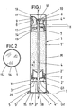
- Fig. 1 den erfindungsgemäß ausgebildeten Spender im Vertikalschnitt,
- Fig. 2 die Unteransicht des Spendergehäuses bei noch nicht aufgestecktem Fußring und
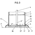
- Fig. 3 eine Herausvergrößerung des Bodenbereichs des Spenders mit in die Lochungsstellung verlagertem Kolbenstangenende (diese Stellung ist in strichpunktierter Linienart wiedergegeben).
- Das lang zylindrisch ausgebildete Gehäuse 1 des Spenders enthält einen Kolben 2. Dessen Randlippen 2' führen sich an der zylindrischen Gehäuseinnenwandung 1'.
- Der Kolben 2 ist ausschließlich in Entleerungsrichtung (Pfeil x) verlagerbar. Er trägt auf seiner dem aufstellseitigen Gehäuseende zugewandten Breitfläche ein erstes Gesperre G1. Es handelt sich um einen sogenannten Klemmodul 3 in Form eines radial ausgerichtete Zacken 3' aufweisenden Sternes aus Federstahl. Sein die Zackenenden umschreibender Durchmesser ist etwas größer als der lichte Durchmesser des Spendergehäuses 1, wodurch sich die Zackenenden als schräg stehende Stützfüße an der Gehäuseinnenwandung 1' entgegen der Richtung des Pfeiles X sperrend verhaken.
- Im Zentrum bildet der Klemmodul 3 ein zweites Gesperre G2 aus. Mit letzterem wirkt eine den Kolben 2 zentral durchsetzende Kolbenstange 4 zusammen. Die radial einwärts gerichteten Zacken 3" des Klemmoduls 3 greifen an der Kolbenstange 4 an. In die Ebene projiziert, ist die von den Zacken 3" belassene Durchtrittsöffnung kleiner als der Durchmesser der Kolbenstange 4.
- Das bodenseitige Ende 4' der Kolbenstange 4 ist zugespitzt. Die Spitze ist als Kegel 4" gestaltet. Eine in Richtung des Pfeiles x erfolgende Bewegung der Kupplungsstange führt aufgrund der kraftschlüssigen Kupplung zur Mitnahme des Kolbens 2. Zu dieser Mitnahme des Kolbens bildet das Spendergehäuse 1 an der dem mit einem Fußring 5 bestückten Standsockel des Gehäuses gegenüberliegenden Seite eine Betätigungshandhabe aus. Es handelt sich um ein balgartig in Richtung des Kolbens 2 zusammendrückbares, sich wieder in seine Grundstellung aufrichtendes Kopfstück 6. Letzteres ist auf den abgesetzten, insofern verschmälerten Hals 7 des Spendergehäuses 1 aufgesteckt. Zufolge der hohen Elastizität bzw. Flexibilität des Kopfstückes ist dieses über einen Ring/Nuteingriff gebrauchsstabil gehalten. Das Kopfstück 6 formt weiter eine querschnittsverringerte, kanalartige Spender-Mundstücköffnung 8. Letztere ist schnabelförmig gestaltet. Ihr vorzugsweise kreisrunder Offnungsmund liegt in der Nähe der Erstreckungsrichtung der Gehäusewandung und ist für die Zeiten der Lagerhaltung mit Hilfe eines dichtschließenden Stopfens 9 verschlossen. Der Stopfen weist Topfform auf mit mundstücköffnungsseitig gerichtetem Topfrand. Der Stopfen ist dadurch hoch flexibel und in seinem Dichtschluß optimiert.
- Das Kopfstück 6 bildet desweiteren im Rücken des die Mundstücköffnung 8 umschreibenden, schnabelartigen Fortsatzes in seiner Deckenpartie eine Drucktasten-Betätigungsfläche 10 aus. Letztere reicht bis kurz vor die gegenüberliegende, gedanklich verlängerte Gehäuse-Wandungsebene und steigt nach außen schräg an.
- Unterhalb dieser Drucktasten-Betätigungsfläche 10 ist die das Spendergehäuse 1 in der Längsmittelachse y - y durchsetzende Kolbenstange 4 mit dem Kopfstück 6 verbunden. Das Kopfstück 6 bildet dazu unterhalb dieser Drucktasten-Betätigungsfläche 10 gehäuseeinwärts gerichtet eine Rastvertiefung 11 aus, in die das pilzkopfartig verbreiterte obere Ende 4'" eingeschnäppert ist. Die Rastvertiefung 11 bildet zur erleichterten Klipszuordnung kolbenseitig eine trichterförmige Erweiterung aus.
- In einem geringen Abstand vor der Rastvertiefung 11 besitzt die Kolbenstange einen Ringwulst 12. Letzterer begrenzt den Betätigungshub H der Kolbenstange 4, indem er gegen die Oberseite einer nabenartigen Hülse 13 im Hals 7 des Spendergehäuses 1 tritt. Die Hülse ist über speichenartige Radialrippen 14 mit dem Hals 7 verbunden. Die führend wirkende Büchse 13 schließt im wesentlichen mit der Oberseite des Halsendes ab und ragt etwa hälftig in den Hals, d. h. in seine Öffnung hinein.
- Während das kopfstückseitige Ende des Spenders über den Stopfen 9 wirksam abgedichtet ist, übernimmt im Bodenbereich des Spendergehäuses eine Membran 15 die luftdichte Abschließung, so daß auch von dorther kein Antrocknen der pastösen Masse mehr möglich ist. Die Membran 15 wird durch Klebung, Heißsiegeln oder dergleichen mit dem Stirnrand 1" des Spendergehäuses verbunden.
- Bei Selbstbetätigung der Drucktasten-Betätigungsfläche 10 wird die Membran 15 zerstört. Hierzu ist die Kolbenstange unter Erfüllung einer entsprechenden Zusatzfunktion als Durchstoßwerkzeug gestaltet und am Ende entsprechend angespitzt (Kegel 4"). Die Kegelspitze liegt in einem Abstand z vor der Membran 15 (vergl. Fig. 3), welcher kleiner ist als der maximale, anschlagdefinierte Betätigungshub H der Kolbenstange 4. Daher kommt es zu einer zentralen Lochung, so daß die Entstehung eines Vakuums unterhalb des Kolbens 2 verhindert wird.
- Wie Fig. 3 weiter entnehmbar, ist die Membran 15 mittels des auf das Spendergehäuse aufgesteckten Fußringes 5 eingespannt. Der Fußring hat außen die Form eines flachen Kegelstumpfes. Sein abwärts gerichteter, zylindrischer Standrand 5' bringt eine verbreiterte Standfläche für den Spender und damit eine erhöhte Standsicherheit. Die Steckzuordnung kann durch Aufprellen des Fußringes 5 realisiert sein. Beim Ausführungsbeispiel ist jedoch eine Rastverbindung bevorzugt. Dazu weist die Mantelfläche des zylindrischen Spendergehäuses einen ringförmigen Vorsprung 16 auf. Letzterer tritt in eine passende Ringnut 17. Die Ringnut 17 befindet sich in einer ebenfalls zylindrischen Ringwand 5" des Fußringes, welche unten in eine horizontale Bodenwand 5'" übergeht. Deren innere Randpartie ist zur peripheren Einspannbefestigung herangezogen, während die sich unmittelbar unterhalb der Membran 15 erstreckende Bodenwand 5"' die Membran nach unten hin abstützt.
- Fluchtend zur Kolbenstange 4 läßt die Bodenwand 5"' eine Durchtrittsöffnung 18 für das Durchstoßwerkzeug frei. Dabei erstreckt sich die Bodenwand 5"' in einem solchen vertikalen Abstand zur bspw. von einer Konsole gebildeten Aufstellfläche F, daß die Spitze des Kegels 4" diese Fläche nicht berührt. Die Ausgabe kann also bei stehendem Spender erfolgen.
- Um den Einschluß von Luft vor dem Kolben möglichst zu vermeiden, weist das zuordnungsseitige, untere Ende des Spendergehäuses einen größeren lichten Durchmesser auf, als der längere Restabschnitt desselben (vergl. Stufe 20).
- Das Kopfstück 6 ist von einer Kappe 19 überfangen. Letztere hält reibungs- oder formschlüssig an einer peripheren Wulst im Befestigungsbereich derselben zwischen unterem Kopfstückrand und Hals 7 des Spendergehäuses 1. Die zylindrische Innenwand 19' der Kappe 19 sichert die Lage des sich mit seinem Rücken an ihr abstützenden Stopfens 9.
- Die Funktion des Spenders ist, kurz zusammengefaßt, wie folgt:
- Nach Abnehmen der Kappe 19 und Niederdrücken der Betätigungsfläche 10 locht die Kolbenstange 4 mit ihrem zugespitzten Ende die Membran 15. Unter Loslassen der Betätigungsfläche wird über den Klemmodul der Kolben 2 in Richtung des Mundstückes verlagert und so die pastöse Masse in den gewünschten Schritten ausgebracht. Hinter dem Kolben kann sich zufolge der Lochung kein Vakuum bilden. Die Lochung schließt sich bei entsprechend rückstellfähigem Membran-Material sogar klappventilartig wieder.
Claims (2)
Priority Applications (1)
| Application Number | Priority Date | Filing Date | Title |
|---|---|---|---|
| AT86106569T ATE38814T1 (de) | 1985-07-26 | 1986-05-14 | Spender fuer pastoese massen. |
Applications Claiming Priority (2)
| Application Number | Priority Date | Filing Date | Title |
|---|---|---|---|
| DE3526804 | 1985-07-26 | ||
| DE19853526804 DE3526804A1 (de) | 1985-07-26 | 1985-07-26 | Spender fuer pastoese massen |
Publications (3)
| Publication Number | Publication Date |
|---|---|
| EP0210355A2 EP0210355A2 (de) | 1987-02-04 |
| EP0210355A3 EP0210355A3 (en) | 1987-08-26 |
| EP0210355B1 true EP0210355B1 (de) | 1988-11-23 |
Family
ID=6276858
Family Applications (1)
| Application Number | Title | Priority Date | Filing Date |
|---|---|---|---|
| EP86106569A Expired EP0210355B1 (de) | 1985-07-26 | 1986-05-14 | Spender für pastöse Massen |
Country Status (4)
| Country | Link |
|---|---|
| US (1) | US4749105A (de) |
| EP (1) | EP0210355B1 (de) |
| AT (1) | ATE38814T1 (de) |
| DE (2) | DE3526804A1 (de) |
Families Citing this family (10)
| Publication number | Priority date | Publication date | Assignee | Title |
|---|---|---|---|---|
| DE3719894A1 (de) * | 1987-06-13 | 1988-12-29 | Bramlage Gmbh | Spenderstift zum auftragen streichfaehiger massen |
| DE8807844U1 (de) * | 1988-06-16 | 1988-08-18 | Pfanstiel, Erich, 7853 Steinen, De | |
| ES2045237T3 (es) * | 1988-06-16 | 1994-01-16 | Erich Pfanstiel | Distribuidor para pastas o fluidos similares. |
| US5273189A (en) * | 1991-02-14 | 1993-12-28 | Societe Technique De Pulverisation - Step | Device for spraying or dispensing a fluid, the device including a member sliding in its admission duct |
| DE4423608C2 (de) * | 1994-07-06 | 1996-07-04 | Bramlage Gmbh | Spender für pastöse Massen |
| US6343718B1 (en) | 1998-10-15 | 2002-02-05 | Loctite Corporation | Unit dose dispense package |
| US20030175376A1 (en) * | 2002-03-15 | 2003-09-18 | Robert Jahn | Extruding devices and methods thereof |
| JP7295855B2 (ja) * | 2017-11-27 | 2023-06-21 | シーカ テクノロジー アクチェンゲゼルシャフト | 2成分型加圧缶 |
| WO2019102025A1 (de) * | 2017-11-27 | 2019-05-31 | Sika Technology Ag | Zweikomponenten-druckdose |
| FR3081113B1 (fr) * | 2018-05-18 | 2020-05-29 | Albea Le Treport | Piston pour reservoir d'un distributeur d'un produit fluide sans reprise d'air |
Family Cites Families (11)
| Publication number | Priority date | Publication date | Assignee | Title |
|---|---|---|---|---|
| US2829801A (en) * | 1955-06-22 | 1958-04-08 | Oil Equipment Lab Inc | Rupturable closure for pressurized containers |
| US3255935A (en) * | 1965-03-29 | 1966-06-14 | Walter B Spatz | Dispensers for fluent masses |
| US3727797A (en) * | 1971-09-07 | 1973-04-17 | P Cronan | Dual compartment spray container |
| DE2217071A1 (de) * | 1972-04-08 | 1974-01-24 | Hagen Perennatorwerk | Vorrichtung zum auspressen von viskosen massen, insbesondere pasten, wie klebstoff, dichtstoff u.dgl. aus verpackungsbehaeltern |
| US4019654A (en) * | 1976-02-25 | 1977-04-26 | Voplex Corporation | Manual cartridge dispenser |
| GB1588406A (en) * | 1976-10-26 | 1981-04-23 | Glaxo Lab Ltd | Ointment container |
| DE2945338A1 (de) * | 1979-11-09 | 1981-05-21 | Joachim 8405 Donaustauf Czech | Spender fuer pastoese produkte |
| DE3045048C2 (de) * | 1980-11-29 | 1986-04-17 | Bramlage Gmbh, 2842 Lohne | Spender für pastöse Massen |
| DE8033450U1 (de) * | 1980-12-17 | 1982-07-22 | Colgate-Palmolive Co., 10022 New York, N.Y. | Laenglicher Behaelter fuer einen Spender fuer pastoeses gut |
| US4696415A (en) * | 1985-02-26 | 1987-09-29 | Philip Meshberg | Apparatus for dispensing products from a self-sealing dispenser |
| US4673106A (en) * | 1985-10-23 | 1987-06-16 | Colgate-Palmolive Company | Dispenser for retaining toothbrush and floss |
-
1985
- 1985-07-26 DE DE19853526804 patent/DE3526804A1/de not_active Withdrawn
-
1986
- 1986-05-14 EP EP86106569A patent/EP0210355B1/de not_active Expired
- 1986-05-14 DE DE8686106569T patent/DE3661255D1/de not_active Expired
- 1986-05-14 AT AT86106569T patent/ATE38814T1/de not_active IP Right Cessation
- 1986-07-23 US US06/889,429 patent/US4749105A/en not_active Expired - Fee Related
Also Published As
| Publication number | Publication date |
|---|---|
| US4749105A (en) | 1988-06-07 |
| EP0210355A3 (en) | 1987-08-26 |
| DE3661255D1 (en) | 1988-12-29 |
| DE3526804A1 (de) | 1987-01-29 |
| ATE38814T1 (de) | 1988-12-15 |
| EP0210355A2 (de) | 1987-02-04 |
Similar Documents
| Publication | Publication Date | Title |
|---|---|---|
| EP0053275B1 (de) | Spender für pastöse Massen | |
| DE3526819A1 (de) | Spender fuer pastoese massen | |
| EP0084638B1 (de) | Spender für pastöse Produkte | |
| EP0210355B1 (de) | Spender für pastöse Massen | |
| EP0347546B1 (de) | Spender für Pasten od. dgl. Medien | |
| EP0194417A2 (de) | Dosierpumpe mit Pumpenbalg an Flaschen oder dergleichen | |
| EP0051790A1 (de) | Spender für pastöse Massen | |
| WO1986001489A1 (en) | Container provided with a closure | |
| DE1287260B (de) | Spraygeraet | |
| EP3206963A1 (de) | Drehverschluss mit inliegender, separat befüllbarer kapsel mit folienversiegelung zum öffnen mittels drehung | |
| DE102005033397A1 (de) | Inhalator für pulverförmige, insbesondere medizinische Substanzen | |
| EP0226777A2 (de) | Spender für pastöse Massen | |
| DE10047722A1 (de) | Von Saugluftstrom des Benutzers aktivierbare Dosiervorrichtung | |
| DE2309547C3 (de) | Gerät zum Füllen und Entleeren eines Flüssigkeitsbehälters, z.B. einer Pipette | |
| EP0691284B1 (de) | Spender für pastöse Massen | |
| EP0083687A1 (de) | Spender für fliessfähige Medien | |
| EP0683891B1 (de) | Vorrichtung zur portionierten entnahme von flüssigkeit | |
| EP0184742B1 (de) | Spender zur portionierten Einzelausgabe von Tabletten, Pasten oder dergleichen | |
| EP0079539B1 (de) | Verschluss für einen pharmazeutischen Behälter | |
| EP0282791A2 (de) | Spender für pastöse Massen | |
| DE3226835A1 (de) | Spender fuer insbesondere pastoese massen | |
| DE3207196A1 (de) | Spender zur abgabe fluessiger, pastoeser oder staubfoermiger fuellgueter | |
| DE4214153A1 (de) | Selbstschliessender verschluss | |
| DE102017104740A1 (de) | Fluidspender | |
| EP0240738A2 (de) | Vorrichtung zum Auftragen von fliessfähigen Massen |
Legal Events
| Date | Code | Title | Description |
|---|---|---|---|
| PUAI | Public reference made under article 153(3) epc to a published international application that has entered the european phase |
Free format text: ORIGINAL CODE: 0009012 |
|
| AK | Designated contracting states |
Kind code of ref document: A2 Designated state(s): AT BE CH DE FR GB IT LI LU NL SE |
|
| PUAL | Search report despatched |
Free format text: ORIGINAL CODE: 0009013 |
|
| AK | Designated contracting states |
Kind code of ref document: A3 Designated state(s): AT BE CH DE FR GB IT LI LU NL SE |
|
| 17P | Request for examination filed |
Effective date: 19870820 |
|
| 17Q | First examination report despatched |
Effective date: 19871119 |
|
| GRAA | (expected) grant |
Free format text: ORIGINAL CODE: 0009210 |
|
| AK | Designated contracting states |
Kind code of ref document: B1 Designated state(s): AT BE CH DE FR GB IT LI LU NL SE |
|
| PG25 | Lapsed in a contracting state [announced via postgrant information from national office to epo] |
Ref country code: IT Free format text: LAPSE BECAUSE OF FAILURE TO SUBMIT A TRANSLATION OF THE DESCRIPTION OR TO PAY THE FEE WITHIN THE PRE;WARNING: LAPSES OF ITALIAN PATENTS WITH EFFECTIVE DATE BEFORE 2007 MAY HAVE OCCURRED AT ANY TIME BEFORE 2007. THE CORRECT EFFECTIVE DATE MAY BE DIFFERENT FROM THE ONE RECORDED.SCRIBED TIME-LIMIT Effective date: 19881123 Ref country code: BE Effective date: 19881123 Ref country code: FR Free format text: THE PATENT HAS BEEN ANNULLED BY A DECISION OF A NATIONAL AUTHORITY Effective date: 19881123 Ref country code: GB Free format text: LAPSE BECAUSE OF NON-PAYMENT OF DUE FEES Effective date: 19881123 Ref country code: SE Effective date: 19881123 Ref country code: NL Effective date: 19881123 |
|
| REF | Corresponds to: |
Ref document number: 38814 Country of ref document: AT Date of ref document: 19881215 Kind code of ref document: T |
|
| REF | Corresponds to: |
Ref document number: 3661255 Country of ref document: DE Date of ref document: 19881229 |
|
| EN | Fr: translation not filed | ||
| NLV1 | Nl: lapsed or annulled due to failure to fulfill the requirements of art. 29p and 29m of the patents act | ||
| PG25 | Lapsed in a contracting state [announced via postgrant information from national office to epo] |
Ref country code: AT Effective date: 19890514 |
|
| PG25 | Lapsed in a contracting state [announced via postgrant information from national office to epo] |
Ref country code: LI Effective date: 19890531 Ref country code: CH Effective date: 19890531 Ref country code: LU Free format text: LAPSE BECAUSE OF NON-PAYMENT OF DUE FEES Effective date: 19890531 |
|
| GBV | Gb: ep patent (uk) treated as always having been void in accordance with gb section 77(7)/1977 [no translation filed] | ||
| REG | Reference to a national code |
Ref country code: CH Ref legal event code: PL |
|
| PGFP | Annual fee paid to national office [announced via postgrant information from national office to epo] |
Ref country code: DE Payment date: 19900508 Year of fee payment: 5 |
|
| PLBE | No opposition filed within time limit |
Free format text: ORIGINAL CODE: 0009261 |
|
| STAA | Information on the status of an ep patent application or granted ep patent |
Free format text: STATUS: NO OPPOSITION FILED WITHIN TIME LIMIT |
|
| 26N | No opposition filed | ||
| PG25 | Lapsed in a contracting state [announced via postgrant information from national office to epo] |
Ref country code: DE Effective date: 19920303 |