EP0206997B1 - Gerät zum Verschliessen und Trennen eines Schlauches, insbesondere eines bei einer Dialyse oder einer Infusion verwendeten Schlauches - Google Patents
Gerät zum Verschliessen und Trennen eines Schlauches, insbesondere eines bei einer Dialyse oder einer Infusion verwendeten Schlauches Download PDFInfo
- Publication number
- EP0206997B1 EP0206997B1 EP86810269A EP86810269A EP0206997B1 EP 0206997 B1 EP0206997 B1 EP 0206997B1 EP 86810269 A EP86810269 A EP 86810269A EP 86810269 A EP86810269 A EP 86810269A EP 0206997 B1 EP0206997 B1 EP 0206997B1
- Authority
- EP
- European Patent Office
- Prior art keywords
- pair
- tube
- projections
- catch
- cutter
- Prior art date
- Legal status (The legal status is an assumption and is not a legal conclusion. Google has not performed a legal analysis and makes no representation as to the accuracy of the status listed.)
- Expired
Links
- 238000000502 dialysis Methods 0.000 title claims description 4
- 238000001802 infusion Methods 0.000 title description 3
- 239000007788 liquid Substances 0.000 claims description 6
- 229920003023 plastic Polymers 0.000 claims description 3
- 239000004033 plastic Substances 0.000 claims description 3
- 239000008280 blood Substances 0.000 claims 1
- 210000004369 blood Anatomy 0.000 claims 1
- 238000010253 intravenous injection Methods 0.000 claims 1
- 210000003323 beak Anatomy 0.000 description 8
- 238000000034 method Methods 0.000 description 5
- 210000003954 umbilical cord Anatomy 0.000 description 3
- 241000894006 Bacteria Species 0.000 description 2
- 238000010241 blood sampling Methods 0.000 description 2
- 238000004519 manufacturing process Methods 0.000 description 2
- 208000027418 Wounds and injury Diseases 0.000 description 1
- 210000001015 abdomen Anatomy 0.000 description 1
- 210000000683 abdominal cavity Anatomy 0.000 description 1
- 239000003086 colorant Substances 0.000 description 1
- 230000006378 damage Effects 0.000 description 1
- 239000012530 fluid Substances 0.000 description 1
- 238000001746 injection moulding Methods 0.000 description 1
- 208000014674 injury Diseases 0.000 description 1
- 239000000463 material Substances 0.000 description 1
- 239000002184 metal Substances 0.000 description 1
- 210000004303 peritoneum Anatomy 0.000 description 1
- 230000003014 reinforcing effect Effects 0.000 description 1
- 238000000926 separation method Methods 0.000 description 1
- 210000003813 thumb Anatomy 0.000 description 1
Images

Classifications
-
- A—HUMAN NECESSITIES
- A61—MEDICAL OR VETERINARY SCIENCE; HYGIENE
- A61M—DEVICES FOR INTRODUCING MEDIA INTO, OR ONTO, THE BODY; DEVICES FOR TRANSDUCING BODY MEDIA OR FOR TAKING MEDIA FROM THE BODY; DEVICES FOR PRODUCING OR ENDING SLEEP OR STUPOR
- A61M5/00—Devices for bringing media into the body in a subcutaneous, intra-vascular or intramuscular way; Accessories therefor, e.g. filling or cleaning devices, arm-rests
-
- A—HUMAN NECESSITIES
- A61—MEDICAL OR VETERINARY SCIENCE; HYGIENE
- A61M—DEVICES FOR INTRODUCING MEDIA INTO, OR ONTO, THE BODY; DEVICES FOR TRANSDUCING BODY MEDIA OR FOR TAKING MEDIA FROM THE BODY; DEVICES FOR PRODUCING OR ENDING SLEEP OR STUPOR
- A61M39/00—Tubes, tube connectors, tube couplings, valves, access sites or the like, specially adapted for medical use
- A61M39/22—Valves or arrangement of valves
- A61M39/28—Clamping means for squeezing flexible tubes, e.g. roller clamps
- A61M39/284—Lever clamps
-
- A—HUMAN NECESSITIES
- A61—MEDICAL OR VETERINARY SCIENCE; HYGIENE
- A61M—DEVICES FOR INTRODUCING MEDIA INTO, OR ONTO, THE BODY; DEVICES FOR TRANSDUCING BODY MEDIA OR FOR TAKING MEDIA FROM THE BODY; DEVICES FOR PRODUCING OR ENDING SLEEP OR STUPOR
- A61M2205/00—General characteristics of the apparatus
- A61M2205/27—General characteristics of the apparatus preventing use
- A61M2205/273—General characteristics of the apparatus preventing use preventing reuse, e.g. of disposables
Definitions
- the invention relates to a device for closing and separating an elastically flexible tube through which a liquid has flowed, in particular a tube used in home dialysis, blood sampling or an infusion, with a first part for receiving the tube, a second part pivotably arranged therein and one on the second part attached cutting edge to cut the hose.
- This two-piece device is used for.
- a patient does not have to carry a bag of fresh or used dialysate on the body when changing home dialysate.
- a catheter is inserted into the patient's abdominal cavity, to which an intermediate piece of an elastically flexible tube connects.
- the end of the Y-shaped tube which is connected to the bag with fresh dialysate and to the bag with used dialysate, is connected to the intermediate piece by means of metal connectors.
- Was be discharged must Y-shaped tube sealed and subsequently isolated - after the spent dialysate from the patient into the outlet Abdomem bag. Closure is achieved by pinching, which is intended to prevent bacteria from entering the patient's abdomen. The separation is then brought out by scissors.
- US Pat. No. 3,822,052 describes a manually operable clamping device for checking the fluid flow through an elastically flexible hose.
- the device consists of a plastic strip that can be bent to form a base part and a lever arm lying above it. Both the base part and the lever arm have opposite supports, between which the inserted tube is clamped. The clamping is achieved by engaging the lever arm in a vertical part of the strip. By swiveling out the vertical part, the lever arm can be released from the vertical part and thus also the pinching off of the hose can be released.
- This device is only used to disconnect the hose, it is in no way equipped to cut (cut) the hose.
- the device for simultaneous clamping and cutting of a hose described in US Pat. No. 3,323,208 comprises a first part and a second part pivotally connected to it according to the preamble of claim 1. Because the knife blade attached to the first part is in the plane of the pivoting movement of the first or second part, the hose to be cut or already cut and clamped extends transversely to the longitudinal axis of the device. As a result, the device with the hose clamped in it and extending transversely to it takes up a relatively large amount of space. In addition, this device does not ensure that the hose is not cut off on the wrong side. Moreover, the knife blade is freely accessible in the open state and there is therefore a considerable risk of injury to the user.
- the invention specified in claim 1 has for its object to provide a device for closing and separating an elastically flexible hose through which a liquid flows, which bring greater safety than before for the patient by no open hose part remains after his disconnection, which always a great risk to life for. represented the patient.
- An unskilled patient should also be allowed to close and separate by hand without effort, and the individual positions of the movement process should also be audible.
- the device is intended to eliminate the previous several work steps.
- the device is also intended to ensure that the hose is not cut off on the wrong side. Ultimately, the manufacturing costs of such a device should be kept low. This object is achieved by the features in the characterizing part of patent claim 1.
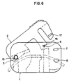
- the first part 1 of the two-part device according to FIG. 2 has two mutually parallel square walls 3, between which a support piece 4 is accommodated.
- the support piece 4 forms part of one of the longitudinal edges of the first part 1 and on the other hand it extends approximately to the middle of the wall height, so that on the other longitudinal edge of part 1 between the walls 3 there is a gap for inserting an elastically flexible hose A for guiding the Liquid arises.
- a hose guide groove 4a provided on the support piece 4 is used to insert the hose A.
- the first part 1 also has a reinforcing plate 19. In the two walls 3 four pairs of grid openings 5, 6, 7, 8 are provided.
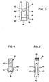
- the second part 2 has a mounting arm 14 with a cutting edge 9b having a cutting edge 9b, a clamping beak 10 and two locking springs 11. There is a first gap 12 between the cutting edge 9 and the clamping beak and between the clamping beak 10 and the locking springs 11 a second gap 13. On both sides of the second part 2, three pairs of projections 15, 16, 17 are provided. The first pair of projections 15 is located on the mounting arm 14, the second pair 16 on the clamping beak 10 and the third pair 17 on the springs 11.
- the tube A (see FIG. 3) is inserted into the guide groove 4a of the support piece 4 so that it is on the Contact piece surface 4b, which faces the first pair of grid openings 5, rests.
- the second part 2 is pivotally connected to the first part 1.
- the movement process of the pivotable second part 2 runs on a circular arc line.
- the circular arc line of the second pair of projections 16 is designated by C in FIG. 2 and the circular arc line of the third pair of projections 17 is designated B.
- the second pair of the projections 16 provided on the clamping beak 10 snaps into the second pair of the grid openings 6 and the third pair of the projections 17 provided on the catch springs 11 in the third and fourth pair of grid openings 7, 8 successively.
- the device In the first engagement position 5, 15 and 6, 16, the device is in the flow position, i. that is, the liquid can flow through the hose A unhindered (Fig. 6).
- the first snap-in position the device is delivered to the patient with the tube and the bags.
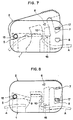
- the second latching position 7, 17, the hose A is pressed by the clamping beak 10 onto the support piece 4 in a Z shape and completely clamped off, so that no medium (liquid or air) can pass through this clamping point (FIG. 7).
- the tube A is cut through the cutting edge 9 (FIG. 8). The clicks of the projections 16, 17 into the grid openings 6, 7, 8 are audible.
- the cutting edge 9 is designed as an angle blade.
- the cutting surface 9a facing the first gap 12 runs in an arcuate manner and corresponds to the arcuate course of the support piece surface 4b which faces the first pair of grid openings 5. This measure ensures that between the second 7, 17 and the third 8, 17 locking position, the hose A is cut transversely at a distance from the clamping point.
- the clamping beak 10 through which the hose A is clamped, consists of full material. For this reason, he can not spring laterally during the movement of the second part 2, as is the case with the springs 11. Therefore, the second pair of protrusions 16 are guided in guide grooves 20 on the inner surfaces of the walls 3.
- the surface 10a of the clamping beak 10 facing the first gap 12 likewise runs in an arc shape, as a result of which the clamping of the hose A is increased still further.
- the individual pairs of grid openings 5, 6, 7, 8 and the corresponding pairs of projections 15, 16, 17 are designed in different geometric shapes and colors.
- the first grid opening pairs 5 are circular
- the second grid opening pairs 6 are triangular
- the third grid opening pairs 7 are quadrangular
- the fourth grid opening pairs 8 are semicircular.
- the associated pairs of projections are designed accordingly.
- the pair of projections 17 on the springs 11 is designed in such a way that after it has snapped into the grid openings 7, it is reopened, ie. H. Swiveling back of the second part 2 is excluded. Of course, this also applies to the locking position 8, 17. These two locking positions ensure double safety for the patient.
- the device consists of only two parts, which are made of hard plastic in an injection molding process.
- the device has a flat shape, at most 1 cm thick, 5 cm long and 3 cm high.
- Such a form of the device can be worn comfortably on the patient's body.
- a thumb corrugation 2a on the edge surface of the second one facing away from the second gap 13 Part 2 the movement process of the same is facilitated.
- the two processes namely the clamping and the subsequent cutting of the hose, are carried out by a single device described above.
- the device is designed so that the hose does not have to be pulled through it.
- the hose is inserted lengthways into the guide trough of the support piece.
- the device is a disposable device and can therefore not be used again. Because it consists of two parts, it is inexpensive to manufacture. Assembly is also efficient because it is done without tools.
Landscapes
- Health & Medical Sciences (AREA)
- Heart & Thoracic Surgery (AREA)
- Animal Behavior & Ethology (AREA)
- General Health & Medical Sciences (AREA)
- Anesthesiology (AREA)
- Biomedical Technology (AREA)
- Hematology (AREA)
- Life Sciences & Earth Sciences (AREA)
- Veterinary Medicine (AREA)
- Engineering & Computer Science (AREA)
- Public Health (AREA)
- Pulmonology (AREA)
- Vascular Medicine (AREA)
- External Artificial Organs (AREA)
- Infusion, Injection, And Reservoir Apparatuses (AREA)
- Separation Using Semi-Permeable Membranes (AREA)
Applications Claiming Priority (2)
| Application Number | Priority Date | Filing Date | Title |
|---|---|---|---|
| CH2670/85A CH669117A5 (de) | 1985-06-24 | 1985-06-24 | Geraet zum verschliessen und trennen eines schlauches, insbesondere eines bei einer dialyse oder einer infusion verwendeten schlauches. |
| CH2670/85 | 1985-06-24 |
Publications (2)
| Publication Number | Publication Date |
|---|---|
| EP0206997A1 EP0206997A1 (de) | 1986-12-30 |
| EP0206997B1 true EP0206997B1 (de) | 1989-05-17 |
Family
ID=4238928
Family Applications (1)
| Application Number | Title | Priority Date | Filing Date |
|---|---|---|---|
| EP86810269A Expired EP0206997B1 (de) | 1985-06-24 | 1986-06-13 | Gerät zum Verschliessen und Trennen eines Schlauches, insbesondere eines bei einer Dialyse oder einer Infusion verwendeten Schlauches |
Country Status (11)
| Country | Link |
|---|---|
| US (1) | US4676476A (enExample) |
| EP (1) | EP0206997B1 (enExample) |
| JP (1) | JPS6253667A (enExample) |
| KR (1) | KR870000078A (enExample) |
| AU (1) | AU589424B2 (enExample) |
| BR (1) | BR8602890A (enExample) |
| CA (1) | CA1275999C (enExample) |
| CH (1) | CH669117A5 (enExample) |
| DE (1) | DE3663332D1 (enExample) |
| IN (1) | IN166095B (enExample) |
| ZA (1) | ZA864478B (enExample) |
Cited By (2)
| Publication number | Priority date | Publication date | Assignee | Title |
|---|---|---|---|---|
| US7686279B2 (en) | 2006-05-12 | 2010-03-30 | Caridianbct, Inc. | Non-reopenable clamp for tubing sets |
| US8940228B2 (en) | 2012-01-11 | 2015-01-27 | Terumo Bct, Inc. | Slidable clamp for port isolation |
Families Citing this family (24)
| Publication number | Priority date | Publication date | Assignee | Title |
|---|---|---|---|---|
| NL8800439A (nl) * | 1988-02-22 | 1989-09-18 | Handelsvennootschap Onder De F | Inrichting voor het doorsnijden van de stengel van een bloem of plant. |
| GB8811834D0 (en) * | 1988-05-19 | 1988-06-22 | Goldstein F | Ribbon curling tool |
| US5205007A (en) * | 1988-05-19 | 1993-04-27 | Fredric Goldstein | Ribbon curling tool |
| JPH0372A (ja) * | 1989-05-26 | 1991-01-07 | Terumo Corp | 医療用容器の交換方法 |
| IT1274666B (it) * | 1994-04-12 | 1997-07-24 | Pierrel Ospedali Spa | Dispositivo di carico e scarico di liquido di dialisi rispetto alla cavita' peritoenale per dialisi peritoneale |
| US5771914A (en) * | 1997-02-13 | 1998-06-30 | Baxter International Inc. | Flexible fluid junction |
| JP2955562B1 (ja) * | 1998-05-29 | 1999-10-04 | 貞亮 前田 | 血液回路離脱装置 |
| US8323228B2 (en) * | 2007-04-12 | 2012-12-04 | Rex Medical L.P. | Dialysis catheter |
| US8262639B2 (en) * | 2002-01-31 | 2012-09-11 | Fenwal, Inc. | Irreversible flow control clamp |
| EP1469904B1 (en) | 2002-01-31 | 2010-09-08 | Fenwal, Inc. | Irreversibly closable flow control clamp |
| US7434779B2 (en) * | 2005-01-28 | 2008-10-14 | Twin Bay Medical, Inc. | Conduit clamp |
| JP5255560B2 (ja) * | 2006-04-05 | 2013-08-07 | ノーブル ハウス グループ ピーティーワイ リミテッド | 管用の非再開式ロックピンチクランプ |
| EP2332611B1 (en) | 2009-12-10 | 2020-06-17 | Fenwal, Inc. | Irreversible flow control clamp for flexible tubes |
| US9833606B2 (en) | 2012-09-07 | 2017-12-05 | Fenwal, Inc. | Non-reopenable flow control clamp |
| WO2016002487A1 (ja) * | 2014-06-30 | 2016-01-07 | 日機装株式会社 | 可撓性チューブのクランプ装置 |
| CN104174079B (zh) * | 2014-08-19 | 2016-08-24 | 贝恩医疗设备(广州)有限公司 | 透析器切膜装置 |
| EP3254724B1 (en) | 2015-02-03 | 2023-08-23 | Nikkiso Company Limited | Clamp device |
| JP6082433B2 (ja) | 2015-06-22 | 2017-02-15 | 日機装株式会社 | クランプ装置 |
| US11040186B2 (en) | 2015-10-28 | 2021-06-22 | Becton, Dickinson And Company | Pinch clamp device |
| JP6706914B2 (ja) | 2015-12-22 | 2020-06-10 | 日機装株式会社 | クランプ装置 |
| US10589082B2 (en) | 2016-02-17 | 2020-03-17 | Becton, Dickinson And Company | Pinch clamp |
| CN109172944A (zh) * | 2018-09-17 | 2019-01-11 | 苏州林华医疗器械股份有限公司 | 一种输液管路止流夹 |
| US20230020041A1 (en) * | 2021-07-19 | 2023-01-19 | Carefusion 303, Inc. | Levered iv flow regulation clamp assembly |
| EP4554657A1 (en) * | 2022-07-12 | 2025-05-21 | Corning Incorporated | Clamp assemblies for clamping tubing and controlling fluid flow |
Family Cites Families (8)
| Publication number | Priority date | Publication date | Assignee | Title |
|---|---|---|---|---|
| US3125108A (en) * | 1964-03-17 | Interstage explosively operated hy- | ||
| US3323208A (en) * | 1965-11-08 | 1967-06-06 | Jr James S Hurley | Simultaneous clamping and cutting means |
| US3598289A (en) * | 1969-06-19 | 1971-08-10 | Norris Dispensers Inc | Dispensing tube valve with cutter |
| US3631858A (en) * | 1969-07-14 | 1972-01-04 | Robert A Ersek | Sever cord |
| US3822052A (en) * | 1973-04-02 | 1974-07-02 | Illinois Tool Works | Shut off clamp |
| US4412380A (en) * | 1981-09-02 | 1983-11-01 | Murray Corporation | Hose cutoff device or tool |
| US4589626A (en) * | 1985-03-13 | 1986-05-20 | Bioresearch Inc. | Hose clamp |
| US4588160A (en) * | 1985-03-27 | 1986-05-13 | Sherwood Medical Company | Tube clamping device |
-
1985
- 1985-06-24 CH CH2670/85A patent/CH669117A5/de not_active IP Right Cessation
-
1986
- 1986-06-12 IN IN521/DEL/86A patent/IN166095B/en unknown
- 1986-06-13 EP EP86810269A patent/EP0206997B1/de not_active Expired
- 1986-06-13 DE DE8686810269T patent/DE3663332D1/de not_active Expired
- 1986-06-16 AU AU58753/86A patent/AU589424B2/en not_active Ceased
- 1986-06-16 ZA ZA864478A patent/ZA864478B/xx unknown
- 1986-06-17 US US06/875,011 patent/US4676476A/en not_active Expired - Fee Related
- 1986-06-19 CA CA000511944A patent/CA1275999C/en not_active Expired - Lifetime
- 1986-06-23 BR BR8602890A patent/BR8602890A/pt not_active IP Right Cessation
- 1986-06-23 KR KR1019860005000A patent/KR870000078A/ko not_active Ceased
- 1986-06-23 JP JP61145030A patent/JPS6253667A/ja active Granted
Cited By (2)
| Publication number | Priority date | Publication date | Assignee | Title |
|---|---|---|---|---|
| US7686279B2 (en) | 2006-05-12 | 2010-03-30 | Caridianbct, Inc. | Non-reopenable clamp for tubing sets |
| US8940228B2 (en) | 2012-01-11 | 2015-01-27 | Terumo Bct, Inc. | Slidable clamp for port isolation |
Also Published As
| Publication number | Publication date |
|---|---|
| US4676476A (en) | 1987-06-30 |
| CH669117A5 (de) | 1989-02-28 |
| ZA864478B (en) | 1987-02-25 |
| AU589424B2 (en) | 1989-10-12 |
| AU5875386A (en) | 1987-01-08 |
| CA1275999C (en) | 1990-11-06 |
| BR8602890A (pt) | 1987-03-17 |
| JPS6253667A (ja) | 1987-03-09 |
| EP0206997A1 (de) | 1986-12-30 |
| DE3663332D1 (en) | 1989-06-22 |
| IN166095B (enExample) | 1990-03-10 |
| KR870000078A (ko) | 1987-02-16 |
| JPH049422B2 (enExample) | 1992-02-20 |
Similar Documents
| Publication | Publication Date | Title |
|---|---|---|
| EP0206997B1 (de) | Gerät zum Verschliessen und Trennen eines Schlauches, insbesondere eines bei einer Dialyse oder einer Infusion verwendeten Schlauches | |
| DE69433326T2 (de) | Vorrichtung zum klammern und schneiden, beispielsweise einer nabelschnur | |
| EP0250369B1 (de) | Dreiwegverteiler zum Flüssigkeitsaustausch | |
| DE3872053T2 (de) | Verfuegbare kassette fuer ein peristaltikpumpen-system. | |
| DE3309918C2 (de) | Saug- und Spülvorrichtung | |
| DE69817516T2 (de) | Nadelschutzvorrichtung | |
| DE60019626T2 (de) | Implantierbare vaskuläre zugangsvorrichtung | |
| DE69232246T2 (de) | Steriles Schweissen von Kunststoffschläuchen | |
| EP0715860B1 (de) | Vorrichtung zum Steuern eines Fluidverlaufes | |
| DE60032008T2 (de) | Saugbeutelanordnung | |
| DE2123131A1 (de) | Klemme für flexible Rohre, insbesondere Rohre von Infusionsbestecken und Verfahren zur Steuerung des Stromes in derartigen Rohren | |
| DE2106248A1 (enExample) | ||
| DE3852638T2 (de) | Beutellose, kontinuierliche, ambulante peritonealdialyse. | |
| EP0391396A2 (de) | Auslass- und Instrumentenkanal für die Arthroskopie | |
| EP0208004A1 (de) | Verfahren und Vorrichtung zum sterilen Docken von Kunststoffschlauchabschnitten oder dergleichen | |
| DE3641644A1 (de) | Durchflusskammer zum entfernen von gasblasen aus einer fluessigkeit | |
| DE1934337A1 (de) | Rollklemmenvorrichtung | |
| DE2750454B2 (de) | Vorrichtung zur Blutentnahme | |
| DE3146348A1 (de) | "einweg-gleitklemme fuer schlaeuche" | |
| DE4031613C2 (de) | Dialysegerät | |
| EP0163979A1 (de) | Anus-praeter-Versorgungssystem | |
| EP0105414B1 (de) | Gefässklemme, insbesondere zum Einsatz in der Mikrochirurgie | |
| DE2659229A1 (de) | Aufhaenge- und klemmvorrichtung fuer einen abflussbeutel | |
| DE3044572A1 (de) | Vorrichtung zur steuerung der in einen schlauch unter der wirkung der schwerkraft ausstroemenden menge einer fluessigkeit | |
| DE4135844A1 (de) | Ventil |
Legal Events
| Date | Code | Title | Description |
|---|---|---|---|
| PUAI | Public reference made under article 153(3) epc to a published international application that has entered the european phase |
Free format text: ORIGINAL CODE: 0009012 |
|
| AK | Designated contracting states |
Kind code of ref document: A1 Designated state(s): BE DE FR GB IT NL SE |
|
| 17P | Request for examination filed |
Effective date: 19870126 |
|
| 17Q | First examination report despatched |
Effective date: 19880321 |
|
| GRAA | (expected) grant |
Free format text: ORIGINAL CODE: 0009210 |
|
| AK | Designated contracting states |
Kind code of ref document: B1 Designated state(s): BE DE FR GB IT NL SE |
|
| REF | Corresponds to: |
Ref document number: 3663332 Country of ref document: DE Date of ref document: 19890622 |
|
| ITF | It: translation for a ep patent filed | ||
| GBT | Gb: translation of ep patent filed (gb section 77(6)(a)/1977) | ||
| ET | Fr: translation filed | ||
| PLBE | No opposition filed within time limit |
Free format text: ORIGINAL CODE: 0009261 |
|
| STAA | Information on the status of an ep patent application or granted ep patent |
Free format text: STATUS: NO OPPOSITION FILED WITHIN TIME LIMIT |
|
| 26N | No opposition filed | ||
| ITTA | It: last paid annual fee | ||
| PGFP | Annual fee paid to national office [announced via postgrant information from national office to epo] |
Ref country code: NL Payment date: 19930630 Year of fee payment: 8 |
|
| PGFP | Annual fee paid to national office [announced via postgrant information from national office to epo] |
Ref country code: DE Payment date: 19930813 Year of fee payment: 8 |
|
| PG25 | Lapsed in a contracting state [announced via postgrant information from national office to epo] |
Ref country code: NL Effective date: 19950101 |
|
| EAL | Se: european patent in force in sweden |
Ref document number: 86810269.0 |
|
| NLV4 | Nl: lapsed or anulled due to non-payment of the annual fee | ||
| PG25 | Lapsed in a contracting state [announced via postgrant information from national office to epo] |
Ref country code: DE Effective date: 19950301 |
|
| PGFP | Annual fee paid to national office [announced via postgrant information from national office to epo] |
Ref country code: GB Payment date: 19950609 Year of fee payment: 10 |
|
| PG25 | Lapsed in a contracting state [announced via postgrant information from national office to epo] |
Ref country code: GB Effective date: 19960613 |
|
| GBPC | Gb: european patent ceased through non-payment of renewal fee |
Effective date: 19960613 |
|
| PGFP | Annual fee paid to national office [announced via postgrant information from national office to epo] |
Ref country code: BE Payment date: 19980518 Year of fee payment: 13 |
|
| PGFP | Annual fee paid to national office [announced via postgrant information from national office to epo] |
Ref country code: SE Payment date: 19980625 Year of fee payment: 13 |
|
| PG25 | Lapsed in a contracting state [announced via postgrant information from national office to epo] |
Ref country code: SE Free format text: THE PATENT HAS BEEN ANNULLED BY A DECISION OF A NATIONAL AUTHORITY Effective date: 19990629 |
|
| PG25 | Lapsed in a contracting state [announced via postgrant information from national office to epo] |
Ref country code: BE Free format text: LAPSE BECAUSE OF NON-PAYMENT OF DUE FEES Effective date: 19990630 |
|
| BERE | Be: lapsed |
Owner name: CONTEMPO PRODUCTS P. HERRLI Effective date: 19990630 |
|
| EUG | Se: european patent has lapsed |
Ref document number: 86810269.0 |
|
| PGFP | Annual fee paid to national office [announced via postgrant information from national office to epo] |
Ref country code: FR Payment date: 20010627 Year of fee payment: 16 |
|
| PG25 | Lapsed in a contracting state [announced via postgrant information from national office to epo] |
Ref country code: FR Free format text: LAPSE BECAUSE OF NON-PAYMENT OF DUE FEES Effective date: 20030228 |
|
| REG | Reference to a national code |
Ref country code: FR Ref legal event code: ST |
|
| PG25 | Lapsed in a contracting state [announced via postgrant information from national office to epo] |
Ref country code: IT Free format text: LAPSE BECAUSE OF NON-PAYMENT OF DUE FEES;WARNING: LAPSES OF ITALIAN PATENTS WITH EFFECTIVE DATE BEFORE 2007 MAY HAVE OCCURRED AT ANY TIME BEFORE 2007. THE CORRECT EFFECTIVE DATE MAY BE DIFFERENT FROM THE ONE RECORDED. Effective date: 20050613 |