EP0206997B1 - Device for closing and severing a tube, in particular a dialysis or infusion tube - Google Patents
Device for closing and severing a tube, in particular a dialysis or infusion tube Download PDFInfo
- Publication number
- EP0206997B1 EP0206997B1 EP86810269A EP86810269A EP0206997B1 EP 0206997 B1 EP0206997 B1 EP 0206997B1 EP 86810269 A EP86810269 A EP 86810269A EP 86810269 A EP86810269 A EP 86810269A EP 0206997 B1 EP0206997 B1 EP 0206997B1
- Authority
- EP
- European Patent Office
- Prior art keywords
- pair
- tube
- projections
- catch
- cutter
- Prior art date
- Legal status (The legal status is an assumption and is not a legal conclusion. Google has not performed a legal analysis and makes no representation as to the accuracy of the status listed.)
- Expired
Links
Images

Classifications
-
- A—HUMAN NECESSITIES
- A61—MEDICAL OR VETERINARY SCIENCE; HYGIENE
- A61M—DEVICES FOR INTRODUCING MEDIA INTO, OR ONTO, THE BODY; DEVICES FOR TRANSDUCING BODY MEDIA OR FOR TAKING MEDIA FROM THE BODY; DEVICES FOR PRODUCING OR ENDING SLEEP OR STUPOR
- A61M5/00—Devices for bringing media into the body in a subcutaneous, intra-vascular or intramuscular way; Accessories therefor, e.g. filling or cleaning devices, arm-rests
-
- A—HUMAN NECESSITIES
- A61—MEDICAL OR VETERINARY SCIENCE; HYGIENE
- A61M—DEVICES FOR INTRODUCING MEDIA INTO, OR ONTO, THE BODY; DEVICES FOR TRANSDUCING BODY MEDIA OR FOR TAKING MEDIA FROM THE BODY; DEVICES FOR PRODUCING OR ENDING SLEEP OR STUPOR
- A61M39/00—Tubes, tube connectors, tube couplings, valves, access sites or the like, specially adapted for medical use
- A61M39/22—Valves or arrangement of valves
- A61M39/28—Clamping means for squeezing flexible tubes, e.g. roller clamps
- A61M39/284—Lever clamps
-
- A—HUMAN NECESSITIES
- A61—MEDICAL OR VETERINARY SCIENCE; HYGIENE
- A61M—DEVICES FOR INTRODUCING MEDIA INTO, OR ONTO, THE BODY; DEVICES FOR TRANSDUCING BODY MEDIA OR FOR TAKING MEDIA FROM THE BODY; DEVICES FOR PRODUCING OR ENDING SLEEP OR STUPOR
- A61M2205/00—General characteristics of the apparatus
- A61M2205/27—General characteristics of the apparatus preventing use
- A61M2205/273—General characteristics of the apparatus preventing use preventing reuse, e.g. of disposables
Landscapes
- Health & Medical Sciences (AREA)
- Heart & Thoracic Surgery (AREA)
- Animal Behavior & Ethology (AREA)
- General Health & Medical Sciences (AREA)
- Anesthesiology (AREA)
- Biomedical Technology (AREA)
- Hematology (AREA)
- Life Sciences & Earth Sciences (AREA)
- Veterinary Medicine (AREA)
- Engineering & Computer Science (AREA)
- Public Health (AREA)
- Pulmonology (AREA)
- Vascular Medicine (AREA)
- External Artificial Organs (AREA)
- Infusion, Injection, And Reservoir Apparatuses (AREA)
- Separation Using Semi-Permeable Membranes (AREA)
Description
Die Erfindung geht aus von einem Gerät zum Verschliessen und Trennen eines von einer Flüssigkeit durchgeflossenen elastisch nachgiebigen Schlauches, insbesondere eines bei einer Heimdialyse, Blutentnahme oder einer Infusion verwendeten Schlauches, mit einem ersten Teil zur Aufnahme des Schlauches, einem darin schwenkbar angeordneten zweiten Teil und einer am zweiten Teil befestigten Schneide zum Durchtrennen des Schlauches.The invention relates to a device for closing and separating an elastically flexible tube through which a liquid has flowed, in particular a tube used in home dialysis, blood sampling or an infusion, with a first part for receiving the tube, a second part pivotably arranged therein and one on the second part attached cutting edge to cut the hose.
Dieses zweiteilige Gerät wird z. B. bei einer Heimdialyse, einer Blutentnahme oder einer Infusion verwendet. Ein Patient braucht beim Heimdialysatwechsel keinen Beutel mit frischem oder verbrauchtem Dialysat auf dem Körper zu tragen. In die Bauchhöhle des Patienten ist ein Katheter eingeführt, an welches sich ein Zwischenstück eines elastisch nachgiebigen Schlauches anschliesst. Mittels Metallkonnektoren wird das Ende des Y-förmigen Schlauches, der an dem Beutel mit frischem Dialysat und an dem Beutel mit verbrauchtem Dialysat angeschlossen ist, mit dem Zwischenstück verbunden. Nachdem der verbrauchte Dialysat aus dem Abdomem des Patienten in den Auslaufbeutel- abgeführt wurde, muss der Y-förmige Schlauch verschlossen und anschliessend getrennt werden. Das Verschliessen wird durch Abklemmen erzielt, wodurch der Eintritt von Bakterien in den Abdomen des Patienten verhindert werden soll. Das Abtrennen wird dann durch eine Schere hervorgebracht.This two-piece device is used for. B. used in home dialysis, blood sampling or an infusion. A patient does not have to carry a bag of fresh or used dialysate on the body when changing home dialysate. A catheter is inserted into the patient's abdominal cavity, to which an intermediate piece of an elastically flexible tube connects. The end of the Y-shaped tube, which is connected to the bag with fresh dialysate and to the bag with used dialysate, is connected to the intermediate piece by means of metal connectors. Was be discharged, must Y-shaped tube sealed and subsequently isolated - after the spent dialysate from the patient into the outlet Abdomem bag. Closure is achieved by pinching, which is intended to prevent bacteria from entering the patient's abdomen. The separation is then brought out by scissors.
Der voneinander getrennte Verschliess- und Trennvorgang verlief bis jetzt in fünf Arbeitsgängen, welche von dem Patienten erlernt werden mussten. Es ist aber immer häufig vorgekommen, dass die Bauchfelle der Patienten doch mit Bakterien infiziert wurden.The separate closing and separating process has so far been carried out in five work steps which the patient had to learn. However, it has always happened that the peritoneum of the patient has been infected with bacteria.
In der US-PS 3 822 052 ist eine von Hand betätigbare Klemmvorrichtung zur Kontrolle des Flüssigkeitsdurchflüsses durch einen elastisch nachgiebigen Schlauch umschrieben. Die Vorrichtung besteht aus einem Kunststoffstreifen, der abgebogen werden kann, um einen Basisteil und einen über ihm liegenden Hebelarm zu bilden. Sowohl der Basisteil als auch der Hebelarm weisen gegenüberliegende Abstützungen auf, zwischen welchen der eingeführte Schlauch abgeklemmt wird. Die Abklemmung wird durch Einrasten des Hebelarmes in einem senkrecht stehenden Teil des Streifens erzielt. Durch das Ausschwenken des senkrecht stehenden Teiles kann der Hebelarm von dem senkrechten Teil gelöst und somit auch die Abklemmung des Schlauches aufgehoben werden. Diese Vorrichtung dient aber nur zum Abklemmen des Schlauches, sie ist keineswegs zum Trennen (Durchschneiden) des Schlauches ausgerüstet.US Pat. No. 3,822,052 describes a manually operable clamping device for checking the fluid flow through an elastically flexible hose. The device consists of a plastic strip that can be bent to form a base part and a lever arm lying above it. Both the base part and the lever arm have opposite supports, between which the inserted tube is clamped. The clamping is achieved by engaging the lever arm in a vertical part of the strip. By swiveling out the vertical part, the lever arm can be released from the vertical part and thus also the pinching off of the hose can be released. This device is only used to disconnect the hose, it is in no way equipped to cut (cut) the hose.
Das in der US-A 3 323 208 beschriebene Gerät zum gleichzeitigen Klemmen und Schneiden eines Schlauches umfasst einen ersten Teil und einen schwenkbar mit diesem verbundenen zweiten Teil gemäß dem Oberbegriff des Anspruchs 1. Weil die am ersten Teil befestigte Messerklinge in der Ebene der Schwenkbewegung des ersten .bzw. zweiten Teiles liegt, erstreckt sich der durchzuschneidende oder bereits durchgeschnittene und eingeklemmte Schlauch quer zur Längsachse des Gerätes. Dadurch beansprucht das Gerät mit dem darin eingeklemmten und sich quer dazu erstreckenden Schlauch relativ viel Platz. Zudem ist bei diesem Gerät nicht sichergestellt, dass der Schlauch nicht auf der falschen Seite abgetrennt wird. Ueberdies ist im geöffneten Zustand die Messerklinge frei zugänglich und es besteht deshalb eine erhebliche Veletzungsgefahr für den Benützer.The device for simultaneous clamping and cutting of a hose described in US Pat. No. 3,323,208 comprises a first part and a second part pivotally connected to it according to the preamble of claim 1. Because the knife blade attached to the first part is in the plane of the pivoting movement of the first or second part, the hose to be cut or already cut and clamped extends transversely to the longitudinal axis of the device. As a result, the device with the hose clamped in it and extending transversely to it takes up a relatively large amount of space. In addition, this device does not ensure that the hose is not cut off on the wrong side. Moreover, the knife blade is freely accessible in the open state and there is therefore a considerable risk of injury to the user.
Weiter ist in der US-A 3 631 858 ein dreiteiliges Gerät zum Klemmen und Trennen der Nabelschnur eines neugeborenen Kindes beschrieben. Zwei der genannten Teile sind um je eine Welle schwenkbar mit dem dritten gemeinsamen Teil verbunden und sind in der Schliessstellung verriegelbar. Der eine erstgenannte und gemeinsame Teil weist je eine Klemmfläche auf, zwischen denen im geschlossenen Zustand des Gerätes die Nabelschnur eingeklemmt ist. An der Seitenfläche des anderen der beiden erstgenannten Teile ist eine Messerklinge befestigt, die zum Durchtrennen der Nabelschnur in Zusammenarbeit mit dem gemeinsamen Teil dient. Bei diesem Gerät sind zwei verschiedene Arbeitsgänge in der richtigen Reihenfolge auszuführen. Weiter haften diesem Gerät die gleichen Nachteile an, wie sie vorangehend mit Bezug auf das in der US-A-3 323 208 beschriebene Gerät angeführt sind.Furthermore, a three-part device for clamping and separating the umbilical cord of a newborn child is described in US Pat. No. 3,631,858. Two of the parts mentioned are each pivotably connected to the third common part and can be locked in the closed position. The first and common part each has a clamping surface between which the umbilical cord is clamped when the device is closed. On the side surface of the other of the first two parts, a knife blade is attached, which is used to cut the umbilical cord in cooperation with the common part. With this device, two different operations must be carried out in the correct order. Furthermore, this device suffers from the same disadvantages as mentioned above with reference to the device described in US-A-3 323 208.
Der im Anspruch 1 angegebenen Erfindung liegt die Aufgabe zugrunde, ein Gerät zum Verschliessen und Trennen eines von einer Flüssigkeit durchgeflossenen, elastisch nachgiebigen Schlauches zu schaffen, welches eine grössere Sicherheit als bisher für den Patienten bringen, indem kein offener Schlauchteil nach seinem Abtrennen verbleibt, was immer eine grosse Lebensgefahr für. den Patienten darstellte. Es soll auch einem unangelernten Patienten das Verschliessen und Trennen von Hand ohne Mühe erlaubt werden, wobei auch die einzelnen Positionen des Bewegungsvorganges akustisch vernehmbar sein sollen. Durch das Gerät sollen die bisher verübten mehreren Arbeitsgänge eliminiert werden. Durch das Gerät soll weiter sichergestellt werden, dass der Schlauch nicht auf einer falschen Seite abgetrennt wird. Schlussendlich sollen die Herstellungskosten eines solchen Gerätes niedrig gehalten werden. Diese Aufgabe wird durch die Merkmale im kennzeichnenden Teil des Patentanspruches 1 gelöst.The invention specified in claim 1 has for its object to provide a device for closing and separating an elastically flexible hose through which a liquid flows, which bring greater safety than before for the patient by no open hose part remains after his disconnection, which always a great risk to life for. represented the patient. An unskilled patient should also be allowed to close and separate by hand without effort, and the individual positions of the movement process should also be audible. The device is intended to eliminate the previous several work steps. The device is also intended to ensure that the hose is not cut off on the wrong side. Ultimately, the manufacturing costs of such a device should be kept low. This object is achieved by the features in the characterizing part of patent claim 1.
Die Erfindung wird nachstehend anhand der Zeichnung beispielsweise näher erläutert. Es zeigen :
- Fig. 1 eine Ansicht eines Teiles des Gerätes, welcher Teil an dem anderen, in der
Figur 2 dargestellten Teil schwenkbar befestigbar ist, - Fig. 2 eine Ansicht des anderen Teiles des Gerätes,
- Fig. 3 eine Seitenansicht des anderen Teiles nach der
Figur 2, - Fig. 4 einen Schnitt entlang der Linie IV-IV der Figur 1,
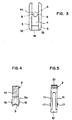
- Fig. 5 eine Seitenansicht der Federn nach der Figur 1 und
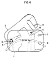
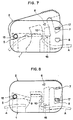
- Fig. 6, 7, 8 Ansichten des aus zwei Teilen zusammengesetzten Gerätes in verschiedenen Einraststellungen.
- 1 is a view of a part of the device, which part is pivotally attached to the other part shown in Figure 2,
- Fig. 2 is a view of the other part of the Device,
- 3 shows a side view of the other part according to FIG. 2,
- 4 shows a section along the line IV-IV of FIG. 1,
- Fig. 5 is a side view of the springs of Figure 1 and
- 6, 7, 8 views of the device composed of two parts in different snap-in positions.
Der erste Teil 1 des zweiteiligen Gerätes nach der Figur 2 weist zwei zueinander parallel verlaufende viereckige Wände 3 auf, zwischen welchen ein Auflagestück 4 untergebracht ist. Das Auflagestück 4 bildet einerseits einen Teil eines der Längsränder des ersten Teiles 1 und andererseits reicht er bis etwa in die Mitte der Wandhöhe, so dass am anderen Längsrand des Teiles 1 zwischen den Wänden 3 ein Spalt zum Einlegen eines elastisch nachgiebigen Schlauches A zum Führen der Flüssigkeit entsteht. Zum Einlegen des Schlauches A dient eine am Auflagestück 4 vorgesehene Schlauchführungsrinne 4a. Der erste Teil 1 weist weiter eine Verstärkungsplatte 19 auf. In den beiden Wänden 3 sind vier gleichachsige Paare von Rasteröffnungen 5, 6, 7, 8 vorgesehen.The first part 1 of the two-part device according to FIG. 2 has two mutually parallel
Der zweite Teil 2 nach der Figur 1 besitzt einen Lagerungsarm 14 mit einer eine Schneidekante 9b aufweisende Schneide 9, einen Klemmschnabel 10 und zwei Rastfedern 11. Zwischen der Schneide 9 und dem Klemmschnabel besteht eine erste Lücke 12 und zwischen dem Klemmschnabel 10 und den Rastfedern 11 eine zweite Lücke 13. Beidseitig des zweiten Teiles 2 sind drei gleichachsige Paare von Vorsprüngen 15, 16, 17 vorgesehen. Das erste Paar der Vorsprünge 15 befindet sich am Lagerungsarm 14, das zweite Paar 16 am Klemmschnabel 10 und das dritte Paar 17 an den Federn 11.The
Bevor das erste Paar der Vorsprünge 15 in die Einlaufsnuten 18 und dann in das erste Paar der Rasteröffnungen 5 des ersten Teiles 1 eingeführt wird, wird in die Führungsrinne 4a des Auflagestückes 4 der Schlauch A (siehe Figur 3) so eingelegt, dass er auf der Auflagestückfläche 4b, die dem ersten Paar der Rasteröffnungen 5 zugekehrt ist, aufliegt. Nach dem Einführen des ersten Paares der Vorsprünge 15 in das erste Paar der Rasteröffnungen 5 ist der zweite Teil 2 mit dem ersten Teil 1 schwenkbar verbunden. Der Bewegungsvorgang des schwenkbaren zweiten Teiles 2 verläuft auf einer Kreisbogenlinie. Die Kreisbogenlinie des zweiten Paares der Vorsprünge 16 ist in der Figur 2 mit C und die Kreisbogenlinie des dritten Paares der Vorsprünge 17 mit B bezeichnet.Before the first pair of
Im Laufe seiner Schwenkbewegung rastet das am Klemmschnabel 10 vorgesehene zweite Paar' der Vorsprünge 16 in dem zweiten Paar der Rasteröffnungen 6 und das an den Rastfedern 11 vorgesehene dritte Paar der Vorsprünge 17 im dritten und vierten Paar von Rasteröffnungen 7, 8 sukzessiv ein. In der ersten Einraststellung 5, 15 und 6, 16 befindet sich das Gerät in Durchflussstellung, d. h., dass die Flüssigkeit durch den Schlauch A unbehindert durchfliessen kann (Fig. 6). Dem Patienten wird das Gerät in dieser ersten Einraststellung mit dem Schlauch und den Beuteln geliefert. In der zweiten Einraststellung 7, 17 wird der Schlauch A von dem Klemmschnabel 10 auf das Auflagestück 4 in Z-Form angedrückt und vollständig abgeklemmt, so dass durch diese Klemmstelle kein Medium (Flüssigkeit oder Luft) durchgehen kann (Fig. 7). Zwischen der zweiten 7, 17 und der dritten 8, 17 Einraststellung wird der Schlauch A durch die Schneide 9 durchgeschnitten (Fig. 8). Das Einrasten der Vorsprünge 16, 17 in den Rasteröffnungen 6, 7, 8 macht sich durch einen Klick-Laut hörbar.In the course of its pivoting movement, the second pair of the
Die Schneide 9 ist als Winkelklinge ausgebildet. Die der ersten Lücke 12 zugekehrte Schneidefläche 9a verläuft bogenförmig und entspricht dem bogenförmigen Verlauf der Auflagestückfläche 4b, die dem ersten Paar der Rasteröffnungen 5 zugekehrt ist. Durch diese Massnahme wird erreicht, dass zwischen der zweiten 7, 17 und der dritten 8, 17 Einraststellung der Schlauch A im Abstand von der Klemmstelle quer abgeschnitten wird.The
Der Klemmschnabel 10, durch welchen der Schlauch A abgeklemmt wird, besteht aus vollem Material. Aus diesem Grunde kann er während des Bewegungsvorganges des zweiten Teiles 2 nicht seitlich federn, wie es der Fall bei den Federn 11 ist. Deswegen wird das zweite Paar der Vorsprünge 16 auf den inneren Flächen der Wände 3 in Führungsnuten 20 geführt. Die der ersten Lücke 12 zugekehrte Fläche 10a des Klemmschnabels 10 verläuft ebenfalls bogenförmig, wodurch das Festklemmen des Schlauches A noch vergrössert wird.The clamping
Um die einzelnen Rasteröffnungspaare 5, 6, 7, 8 und die ihnen entsprechenden Vorsprungspaare 15, 16, 17 auch visuell voneinander besser unterscheiden zu können, sind sie in voneinander unterschiedlichen geometrischen Formen und Farben ausgeführt. So sind die ersten Rasteröffnungspaare 5 kreisförmig, die zweiten Rasteröffnungspaare 6 dreieckig, die dritten Rasteröffnungspaare 7 viereckig und die vierten Rasteröffnungspaare 8 halbkreisförmig ausgebildet. Dementsprechend sind auch die zugehörigen Vorsprungspaare gestaltet. Wie aus der Figur 5 ersichtlich ist, ist das Vorsprungspaar 17 auf den Federn 11 so gestaltet, dass nach dem Einrasten desselben in den Rasteröffnungen 7 eine Wieder- öffnung, d. h. Zurückschwenken des zweiten Teiles 2, ausgeschlossen ist. Dies gilt selbstverständlich auch für die Einraststellung 8, 17. Diese zwei Einraststellungen gewähren eine doppelte Sicherheit für den Patienten.In order to be able to visually differentiate the individual pairs of
Das Gerät besteht aus nur zwei Teilen, die aus Hartkunststoff in einem Spritzgussverfahren hergestellt sind. Das Gerät hat eine flache, höchstens 1 cm dicke, 5 cm lange und 3 cm hohe Form. Eine solche Form des Gerätes kann vom Patienten angenehm an seinem Körper getragen werden. Durch eine Daumenriffelung 2a an der der zweiten Lücke 13 abgekehrten Randfläche des zweiten Teiles 2 wird der Bewegungsvorgang desselben erleichtert.The device consists of only two parts, which are made of hard plastic in an injection molding process. The device has a flat shape, at most 1 cm thick, 5 cm long and 3 cm high. Such a form of the device can be worn comfortably on the patient's body. By a
Die beiden Vorgänge, nämlich das Klemmen und das nachträgliche Durchschneiden des Schlauches werden durch ein einziges oben beschriebenes Gerät ausgeführt. Das Gerät ist so konstruiert, dass der Schlauch durch dasselbe nicht durchgezogen werden muss. Der Schlauch wird in die Führungsrinne des Auflegestückes längsweise eingelegt. Das Gerät ist ein Wegwerfgerät und kann also nicht wieder verwendet werden. Weil es aus zwei Teilen besteht, ist seine Fabrikation preisgünstig. Auch die Montage ist rationell, weil sie ohne Werkzeuge verläuft.The two processes, namely the clamping and the subsequent cutting of the hose, are carried out by a single device described above. The device is designed so that the hose does not have to be pulled through it. The hose is inserted lengthways into the guide trough of the support piece. The device is a disposable device and can therefore not be used again. Because it consists of two parts, it is inexpensive to manufacture. Assembly is also efficient because it is done without tools.
Claims (8)
Applications Claiming Priority (2)
| Application Number | Priority Date | Filing Date | Title |
|---|---|---|---|
| CH2670/85A CH669117A5 (en) | 1985-06-24 | 1985-06-24 | DEVICE FOR SEALING AND DISCONNECTING A HOSE, IN PARTICULAR A HOSE USED IN DIALYSIS OR INFUSION. |
| CH2670/85 | 1985-06-24 |
Publications (2)
| Publication Number | Publication Date |
|---|---|
| EP0206997A1 EP0206997A1 (en) | 1986-12-30 |
| EP0206997B1 true EP0206997B1 (en) | 1989-05-17 |
Family
ID=4238928
Family Applications (1)
| Application Number | Title | Priority Date | Filing Date |
|---|---|---|---|
| EP86810269A Expired EP0206997B1 (en) | 1985-06-24 | 1986-06-13 | Device for closing and severing a tube, in particular a dialysis or infusion tube |
Country Status (11)
| Country | Link |
|---|---|
| US (1) | US4676476A (en) |
| EP (1) | EP0206997B1 (en) |
| JP (1) | JPS6253667A (en) |
| KR (1) | KR870000078A (en) |
| AU (1) | AU589424B2 (en) |
| BR (1) | BR8602890A (en) |
| CA (1) | CA1275999C (en) |
| CH (1) | CH669117A5 (en) |
| DE (1) | DE3663332D1 (en) |
| IN (1) | IN166095B (en) |
| ZA (1) | ZA864478B (en) |
Cited By (2)
| Publication number | Priority date | Publication date | Assignee | Title |
|---|---|---|---|---|
| US7686279B2 (en) | 2006-05-12 | 2010-03-30 | Caridianbct, Inc. | Non-reopenable clamp for tubing sets |
| US8940228B2 (en) | 2012-01-11 | 2015-01-27 | Terumo Bct, Inc. | Slidable clamp for port isolation |
Families Citing this family (24)
| Publication number | Priority date | Publication date | Assignee | Title |
|---|---|---|---|---|
| NL8800439A (en) * | 1988-02-22 | 1989-09-18 | Handelsvennootschap Onder De F | DEVICE FOR CUTTING THE STEM OF A FLOWER OR PLANT. |
| GB8811834D0 (en) * | 1988-05-19 | 1988-06-22 | Goldstein F | Ribbon curling tool |
| US5205007A (en) * | 1988-05-19 | 1993-04-27 | Fredric Goldstein | Ribbon curling tool |
| JPH0372A (en) * | 1989-05-26 | 1991-01-07 | Terumo Corp | Exchange method for container for medical treatment |
| IT1274666B (en) * | 1994-04-12 | 1997-07-24 | Pierrel Ospedali Spa | LOADING AND UNLOADING DEVICE FOR DIALYSIS LIQUID COMPARED TO PERITOENAL CAVITY FOR PERITONEAL DIALYSIS |
| US5771914A (en) * | 1997-02-13 | 1998-06-30 | Baxter International Inc. | Flexible fluid junction |
| JP2955562B1 (en) * | 1998-05-29 | 1999-10-04 | 貞亮 前田 | Blood circuit disconnection device |
| US8323228B2 (en) * | 2007-04-12 | 2012-12-04 | Rex Medical L.P. | Dialysis catheter |
| US20050215975A1 (en) | 2002-01-31 | 2005-09-29 | Jean-Marie Mathias | Irreversibly closable flow control clamp |
| US8262639B2 (en) * | 2002-01-31 | 2012-09-11 | Fenwal, Inc. | Irreversible flow control clamp |
| US7434779B2 (en) * | 2005-01-28 | 2008-10-14 | Twin Bay Medical, Inc. | Conduit clamp |
| AU2007233576B2 (en) * | 2006-04-05 | 2013-10-03 | Noble House Group Pty Ltd | Non-reopening locking pinch clamp for tubing |
| EP2332611B1 (en) | 2009-12-10 | 2020-06-17 | Fenwal, Inc. | Irreversible flow control clamp for flexible tubes |
| US9833606B2 (en) | 2012-09-07 | 2017-12-05 | Fenwal, Inc. | Non-reopenable flow control clamp |
| CN106659829B (en) | 2014-06-30 | 2020-03-03 | 日机装株式会社 | Clamping device for flexible pipe |
| CN104174079B (en) * | 2014-08-19 | 2016-08-24 | 贝恩医疗设备(广州)有限公司 | Dialyser film cutting apparatus |
| WO2016125820A1 (en) | 2015-02-03 | 2016-08-11 | 日機装株式会社 | Clamp device |
| JP6082433B2 (en) | 2015-06-22 | 2017-02-15 | 日機装株式会社 | Clamping device |
| US11040186B2 (en) | 2015-10-28 | 2021-06-22 | Becton, Dickinson And Company | Pinch clamp device |
| JP6706914B2 (en) | 2015-12-22 | 2020-06-10 | 日機装株式会社 | Clamp device |
| US10589082B2 (en) * | 2016-02-17 | 2020-03-17 | Becton, Dickinson And Company | Pinch clamp |
| CN109172944A (en) * | 2018-09-17 | 2019-01-11 | 苏州林华医疗器械股份有限公司 | A kind of infusion pipeline flow-stopping clip |
| US20230020041A1 (en) * | 2021-07-19 | 2023-01-19 | Carefusion 303, Inc. | Levered iv flow regulation clamp assembly |
| WO2024015209A1 (en) * | 2022-07-12 | 2024-01-18 | Corning Incorporated | Clamp assemblies for clamping tubing and controlling fluid flow |
Family Cites Families (8)
| Publication number | Priority date | Publication date | Assignee | Title |
|---|---|---|---|---|
| US3125108A (en) * | 1964-03-17 | Interstage explosively operated hy- | ||
| US3323208A (en) * | 1965-11-08 | 1967-06-06 | Jr James S Hurley | Simultaneous clamping and cutting means |
| US3598289A (en) * | 1969-06-19 | 1971-08-10 | Norris Dispensers Inc | Dispensing tube valve with cutter |
| US3631858A (en) * | 1969-07-14 | 1972-01-04 | Robert A Ersek | Sever cord |
| US3822052A (en) * | 1973-04-02 | 1974-07-02 | Illinois Tool Works | Shut off clamp |
| US4412380A (en) * | 1981-09-02 | 1983-11-01 | Murray Corporation | Hose cutoff device or tool |
| US4589626A (en) * | 1985-03-13 | 1986-05-20 | Bioresearch Inc. | Hose clamp |
| US4588160A (en) * | 1985-03-27 | 1986-05-13 | Sherwood Medical Company | Tube clamping device |
-
1985
- 1985-06-24 CH CH2670/85A patent/CH669117A5/en not_active IP Right Cessation
-
1986
- 1986-06-12 IN IN521/DEL/86A patent/IN166095B/en unknown
- 1986-06-13 EP EP86810269A patent/EP0206997B1/en not_active Expired
- 1986-06-13 DE DE8686810269T patent/DE3663332D1/en not_active Expired
- 1986-06-16 AU AU58753/86A patent/AU589424B2/en not_active Ceased
- 1986-06-16 ZA ZA864478A patent/ZA864478B/en unknown
- 1986-06-17 US US06/875,011 patent/US4676476A/en not_active Expired - Fee Related
- 1986-06-19 CA CA000511944A patent/CA1275999C/en not_active Expired - Lifetime
- 1986-06-23 KR KR1019860005000A patent/KR870000078A/en not_active Application Discontinuation
- 1986-06-23 BR BR8602890A patent/BR8602890A/en not_active IP Right Cessation
- 1986-06-23 JP JP61145030A patent/JPS6253667A/en active Granted
Cited By (2)
| Publication number | Priority date | Publication date | Assignee | Title |
|---|---|---|---|---|
| US7686279B2 (en) | 2006-05-12 | 2010-03-30 | Caridianbct, Inc. | Non-reopenable clamp for tubing sets |
| US8940228B2 (en) | 2012-01-11 | 2015-01-27 | Terumo Bct, Inc. | Slidable clamp for port isolation |
Also Published As
| Publication number | Publication date |
|---|---|
| ZA864478B (en) | 1987-02-25 |
| DE3663332D1 (en) | 1989-06-22 |
| US4676476A (en) | 1987-06-30 |
| CH669117A5 (en) | 1989-02-28 |
| EP0206997A1 (en) | 1986-12-30 |
| KR870000078A (en) | 1987-02-16 |
| IN166095B (en) | 1990-03-10 |
| BR8602890A (en) | 1987-03-17 |
| AU589424B2 (en) | 1989-10-12 |
| CA1275999C (en) | 1990-11-06 |
| JPS6253667A (en) | 1987-03-09 |
| AU5875386A (en) | 1987-01-08 |
| JPH049422B2 (en) | 1992-02-20 |
Similar Documents
| Publication | Publication Date | Title |
|---|---|---|
| EP0206997B1 (en) | Device for closing and severing a tube, in particular a dialysis or infusion tube | |
| DE69433326T2 (en) | DEVICE FOR CLAMPING AND CUTTING, EXAMPLE OF A CABLE | |
| EP0250369B1 (en) | Three-way valve | |
| DE3309918C2 (en) | Suction and flushing device | |
| DE69817516T2 (en) | Needle protector | |
| EP0715860B1 (en) | Flow sequence control device | |
| DE3641644C3 (en) | Flow chamber for removing gas bubbles from a liquid | |
| DE2242539C2 (en) | Regulating clamp for flexible tubes, especially for infusion and transfusion devices | |
| DE2123131A1 (en) | Clamp for flexible pipes, in particular pipes for infusion sets and method for controlling the current in such pipes | |
| DE2106248A1 (en) | ||
| EP0036642A2 (en) | Catheter | |
| DE3001992A1 (en) | UROSTOMIC BAG | |
| DE2634368A1 (en) | SELF-SEALING DEVICE FOR REPEATED ACCESSIBILITY OF A HOSE LINE | |
| DE4031613C2 (en) | Dialysis machine | |
| DE3146348A1 (en) | "DISPOSABLE SLIDING CLAMP FOR TUBES" | |
| EP0163979A1 (en) | Anus-praeter supply system | |
| EP0105414B1 (en) | Clip for a blood vessel, especially for use in microsurgery | |
| EP3421059B1 (en) | Dialyser with an improved arrangement (dialyser holder and connectors) | |
| DE2447513A1 (en) | Suction curette for uterus evacuation or curettage - with continuous flushing of suction inlet especially with saline | |
| EP1206216B1 (en) | Syringe | |
| EP0488288B1 (en) | Tubing set for peritoneal dialysis | |
| DE4012848A1 (en) | Plastics closure clip for foil bags | |
| EP0538569B1 (en) | Closing device for a flexible holder and holder with such a closing device | |
| DE2140101A1 (en) | DEVICE FOR THE SEALING OF BENDABLE HOSES TO BE SEALED | |
| DE2543154C3 (en) | Plastic container for parenteral solutions and combination with an administration device |
Legal Events
| Date | Code | Title | Description |
|---|---|---|---|
| PUAI | Public reference made under article 153(3) epc to a published international application that has entered the european phase |
Free format text: ORIGINAL CODE: 0009012 |
|
| AK | Designated contracting states |
Kind code of ref document: A1 Designated state(s): BE DE FR GB IT NL SE |
|
| 17P | Request for examination filed |
Effective date: 19870126 |
|
| 17Q | First examination report despatched |
Effective date: 19880321 |
|
| GRAA | (expected) grant |
Free format text: ORIGINAL CODE: 0009210 |
|
| AK | Designated contracting states |
Kind code of ref document: B1 Designated state(s): BE DE FR GB IT NL SE |
|
| REF | Corresponds to: |
Ref document number: 3663332 Country of ref document: DE Date of ref document: 19890622 |
|
| ITF | It: translation for a ep patent filed |
Owner name: UFFICIO TECNICO ING. A. MANNUCCI |
|
| GBT | Gb: translation of ep patent filed (gb section 77(6)(a)/1977) | ||
| ET | Fr: translation filed | ||
| PLBE | No opposition filed within time limit |
Free format text: ORIGINAL CODE: 0009261 |
|
| STAA | Information on the status of an ep patent application or granted ep patent |
Free format text: STATUS: NO OPPOSITION FILED WITHIN TIME LIMIT |
|
| 26N | No opposition filed | ||
| ITTA | It: last paid annual fee | ||
| PGFP | Annual fee paid to national office [announced via postgrant information from national office to epo] |
Ref country code: NL Payment date: 19930630 Year of fee payment: 8 |
|
| PGFP | Annual fee paid to national office [announced via postgrant information from national office to epo] |
Ref country code: DE Payment date: 19930813 Year of fee payment: 8 |
|
| PG25 | Lapsed in a contracting state [announced via postgrant information from national office to epo] |
Ref country code: NL Effective date: 19950101 |
|
| EAL | Se: european patent in force in sweden |
Ref document number: 86810269.0 |
|
| NLV4 | Nl: lapsed or anulled due to non-payment of the annual fee | ||
| PG25 | Lapsed in a contracting state [announced via postgrant information from national office to epo] |
Ref country code: DE Effective date: 19950301 |
|
| PGFP | Annual fee paid to national office [announced via postgrant information from national office to epo] |
Ref country code: GB Payment date: 19950609 Year of fee payment: 10 |
|
| PG25 | Lapsed in a contracting state [announced via postgrant information from national office to epo] |
Ref country code: GB Effective date: 19960613 |
|
| GBPC | Gb: european patent ceased through non-payment of renewal fee |
Effective date: 19960613 |
|
| PGFP | Annual fee paid to national office [announced via postgrant information from national office to epo] |
Ref country code: BE Payment date: 19980518 Year of fee payment: 13 |
|
| PGFP | Annual fee paid to national office [announced via postgrant information from national office to epo] |
Ref country code: SE Payment date: 19980625 Year of fee payment: 13 |
|
| PG25 | Lapsed in a contracting state [announced via postgrant information from national office to epo] |
Ref country code: SE Free format text: THE PATENT HAS BEEN ANNULLED BY A DECISION OF A NATIONAL AUTHORITY Effective date: 19990629 |
|
| PG25 | Lapsed in a contracting state [announced via postgrant information from national office to epo] |
Ref country code: BE Free format text: LAPSE BECAUSE OF NON-PAYMENT OF DUE FEES Effective date: 19990630 |
|
| BERE | Be: lapsed |
Owner name: CONTEMPO PRODUCTS P. HERRLI Effective date: 19990630 |
|
| EUG | Se: european patent has lapsed |
Ref document number: 86810269.0 |
|
| PGFP | Annual fee paid to national office [announced via postgrant information from national office to epo] |
Ref country code: FR Payment date: 20010627 Year of fee payment: 16 |
|
| PG25 | Lapsed in a contracting state [announced via postgrant information from national office to epo] |
Ref country code: FR Free format text: LAPSE BECAUSE OF NON-PAYMENT OF DUE FEES Effective date: 20030228 |
|
| REG | Reference to a national code |
Ref country code: FR Ref legal event code: ST |
|
| PG25 | Lapsed in a contracting state [announced via postgrant information from national office to epo] |
Ref country code: IT Free format text: LAPSE BECAUSE OF NON-PAYMENT OF DUE FEES;WARNING: LAPSES OF ITALIAN PATENTS WITH EFFECTIVE DATE BEFORE 2007 MAY HAVE OCCURRED AT ANY TIME BEFORE 2007. THE CORRECT EFFECTIVE DATE MAY BE DIFFERENT FROM THE ONE RECORDED. Effective date: 20050613 |