EP0204140A1 - Diapositiv-Rähmchen - Google Patents
Diapositiv-Rähmchen Download PDFInfo
- Publication number
- EP0204140A1 EP0204140A1 EP86105831A EP86105831A EP0204140A1 EP 0204140 A1 EP0204140 A1 EP 0204140A1 EP 86105831 A EP86105831 A EP 86105831A EP 86105831 A EP86105831 A EP 86105831A EP 0204140 A1 EP0204140 A1 EP 0204140A1
- Authority
- EP
- European Patent Office
- Prior art keywords
- slide
- frame
- film
- slot
- clamping
- Prior art date
- Legal status (The legal status is an assumption and is not a legal conclusion. Google has not performed a legal analysis and makes no representation as to the accuracy of the status listed.)
- Withdrawn
Links
Images

Classifications
-
- G—PHYSICS
- G03—PHOTOGRAPHY; CINEMATOGRAPHY; ANALOGOUS TECHNIQUES USING WAVES OTHER THAN OPTICAL WAVES; ELECTROGRAPHY; HOLOGRAPHY
- G03D—APPARATUS FOR PROCESSING EXPOSED PHOTOGRAPHIC MATERIALS; ACCESSORIES THEREFOR
- G03D15/00—Apparatus for treating processed material
- G03D15/10—Mounting, e.g. of processed material in a frame
Definitions
- the invention relates to a slide frame according to the preamble of patent claim 1.
- Such a slide frame is known from DE AS 12 64 o98 by the applicant.
- the film is inserted into the frame through the insertion slot. After the leading edge of the film in the direction of movement of the film has passed through the entire image window of the slide frame, it must be pushed back into the slide frame on the side opposite the insertion slot. Difficulties arise with a film that is warped.
- plastic frames are designed with a pocket closed on one side to hold the slide, as can be seen, for example, from AT-PS 231 195.
- a slide is generally not designed to be completely flat, since its development, particularly in trailer developing machines or with rapid drying, can lead to considerable warping of the film.
- AT-PS 231 195 discloses that the edges of the above-mentioned receiving groove for the slide, opposite the insertion slot and extending transversely to the insertion direction of the slide, are beveled. These bevels allow the slide to slide easily from the insertion slot of the frame into the projection position, even if the slide is not quite flat, the groove holding the film in the correct position.
- the funnel of the receiving groove formed by the bevels of the picture window edge is not large enough to be able to insert curved film without problems.
- DE-PS 1 294 065 also deals with the difficulty that the film piece abuts on the image window boundary opposite the insertion slot or the insertion opening and therefore cannot be brought into its intended position. It teaches to remedy this disadvantage that in the The cutting station of each slide is cut concavely at its front end before being inserted into the frame. However, this measure requires an expensive, complex cutting tool.
- the concave wedge can also be made very flat and therefore not very effective, since the image bridges are often very narrow and the gate would be visible during projection.
- the object of the invention is to provide a slide frame according to the preamble of claim 1, in which the slide film can be inserted reliably and easily even if it is warped, and which provides an improved clamping effect for the slide in the projection position .
- this object is achieved by the features specified in the characterizing part of patent claim 1.
- the slide can be inserted up to its projection position, specifically on framing machines known per se and regardless of whether the slide frame is produced by the injection molding process or in an extrusion and stamping process.
- the fact that the film bed is narrowed by a clamping rib, which is arranged on an image window edge extending perpendicular to the insertion direction of the slide, provides an improved clamping effect for the slide in the projection position.
- the film bed narrowed by the clamping rib according to the invention conveys a deformation, i.e. a curvature of the film and, in cooperation with the clamping rib, causes a sufficient clamping effect.
- the frame known from DE-PS 1 214 898 can be widened either on one or on the other side of its tubular receiving pocket for the slide, so that a slide frame with a tubular receiving pocket for the slide is better and better in the area of the insertion slots can be expanded more easily.
- This advantage is related to using the frame on an automatic framing machine.
- Such a frame no longer requires pre-orientation, as is indispensable for frames with a sack-like receiving pocket, in order for the pocket to be inserted automatically in order to be able to automatically insert the slide into the frame.
- An advantageous development of the invention is characterized in that the film bed is narrowed by two opposing clamping ribs which are arranged on the picture window edges which extend perpendicular to the insertion direction of the slide. As a result, the clamping effect is further improved.
- the slide frame according to the invention can be widened by means of wedges which are inserted laterally into the slide frame.
- a particularly advantageous embodiment of such an expansion wedge for expanding a slide frame according to one of the claims is characterized in that the wedge is formed with a passage opening for the slide.
- Such a configuration of the expansion wedge allows a particularly simple and reliable introduction of the slide into the slide frame.
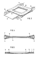
- the slide frame 1 made of elastic plastic is formed with two end-side, oppositely arranged, elastically expandable insertion slots.
- the frame edge parts lying to the side of the insertion path of the slide are formed in the region of the insertion slot in such a way that forces acting in pairs against one another and directed perpendicularly to defined points of these specially designed frame edge parts can cause the insertion slot to widen.
- the introductory slots 2,3 as shown in FIGS. 1 and 2 formed laterally into the side strips, for example 4 to form an insertion slot that is continuous over the width of the frame.
- wedges 5, 6 can be inserted from the side strips 4, 4a of the frame 1 into the continuous gap of the insertion slots 2, 3.
- the wedge 5 is formed with a passage opening 7 for the slide 8.
- the direction of insertion for the slide is indicated by two arrows in FIG. 2.
- the film bed is narrowed by two opposing clamping ribs 13, 14, which are arranged on the picture window edges extending perpendicular to the insertion direction of the slide. These ribs 13, 14 are shown in each case in the drawings.
- the clamping ribs 13, 14 arranged at the edges of the picture window perpendicular to the insertion direction of the slide on the one hand cause a narrowing of the film bed and on the other hand a curvature of the slide.
- the combination of these measures provides a sufficient clamping effect on the slide, which is fixed in this way in its projection position in the frame.
- the slide can nevertheless be inserted mechanically into the slide frame according to the invention.
- the opposite insertion slots 2, 3 are preferably widened simultaneously by means of the wedges 5, 6.
- the slide can be easily and correctly inserted into its projection position in the frame.
- the expansion wedges 5, 6 are again guided out of the insertion slots 2, 3, so that the expansion process is ended.
- the Daipositiv is properly fixed in its projection position using the elasticity of the plastic of the frame by means of the clamping ribs 13, 14.
- the invention brings about a reliable film clamping in the slide frame according to the invention.
- the purpose of the film clamp is so that the film is properly fixed in its projection position in the frame.
- This film clamping is brought about by narrowing the film bed and clamping the slide on two sides of the image window boundary. A certain curvature is imposed on the film. Nevertheless, due to the preferably simultaneous expansion of the frame at its two ends, the film can be easily and perfectly inserted into its projection position.
- a side effect of the film clamping according to the invention is an anti-pop effect.
Landscapes
- Physics & Mathematics (AREA)
- General Physics & Mathematics (AREA)
- Overhead Projectors And Projection Screens (AREA)
- Mirrors, Picture Frames, Photograph Stands, And Related Fastening Devices (AREA)
- Sheet Holders (AREA)
- Photographic Processing Devices Using Wet Methods (AREA)
Applications Claiming Priority (2)
| Application Number | Priority Date | Filing Date | Title |
|---|---|---|---|
| DE3517873 | 1985-05-17 | ||
| DE19853517873 DE3517873A1 (de) | 1985-05-17 | 1985-05-17 | Diapositiv-rahmen und verfahren zum einfuehren eines diapositivs in einen solchen rahmen |
Publications (1)
| Publication Number | Publication Date |
|---|---|
| EP0204140A1 true EP0204140A1 (de) | 1986-12-10 |
Family
ID=6271039
Family Applications (1)
| Application Number | Title | Priority Date | Filing Date |
|---|---|---|---|
| EP86105831A Withdrawn EP0204140A1 (de) | 1985-05-17 | 1986-04-28 | Diapositiv-Rähmchen |
Country Status (6)
| Country | Link |
|---|---|
| US (1) | US4738040A (enExample) |
| EP (1) | EP0204140A1 (enExample) |
| JP (2) | JPS6230235A (enExample) |
| CA (1) | CA1268037A (enExample) |
| DE (1) | DE3517873A1 (enExample) |
| ES (1) | ES296646Y (enExample) |
Families Citing this family (14)
| Publication number | Priority date | Publication date | Assignee | Title |
|---|---|---|---|---|
| US4929056A (en) * | 1988-09-08 | 1990-05-29 | Grumman Aerospace Corporation | Apparatus for opening and holding a frame and a method of mounting an optical element in a frame |
| DE8813514U1 (de) * | 1988-10-27 | 1988-12-15 | L + N-Plast Kunststoffverarbeitung GmbH & Co Betriebs KG, 8111 Untereglfing | Diapositiv-Rähmchen |
| US5182897A (en) * | 1992-01-15 | 1993-02-02 | Pakon, Inc. | Slide mounter with movable knife assembly |
| US5216872A (en) * | 1992-01-15 | 1993-06-08 | Pakon, Inc. | Slide mounter with motor/arm interlock |
| US5263301A (en) * | 1992-01-15 | 1993-11-23 | Pakon, Inc. | Slide mounter with in-plane film pusher |
| US5187918A (en) * | 1992-01-15 | 1993-02-23 | Pakon, Inc. | Slide mounter with bridging film advance |
| US5222347A (en) * | 1992-01-15 | 1993-06-29 | Pakon, Inc. | Slide mounter with spring loaded insert guides |
| US5187923A (en) * | 1992-01-15 | 1993-02-23 | Pakon, Inc. | Slide mounter with positive stop film placement |
| US5195653A (en) * | 1992-01-15 | 1993-03-23 | Pakon, Inc. | Slide mounter with improved slide mount advance |
| US6065234A (en) * | 1998-11-17 | 2000-05-23 | Pakon, Inc. | Post plastic lens photographic slide mount |
| US7210270B1 (en) * | 2000-10-20 | 2007-05-01 | Steelcase Development Corporation | Partition system with elevated raceway |
| USD463258S1 (en) | 2000-10-30 | 2002-09-24 | Downing Displays, Inc. | Connector for modular display panels |
| USD563211S1 (en) * | 2002-03-22 | 2008-03-04 | Woodcraft Industries, Inc. | Tenon |
| USD496967S1 (en) | 2003-07-01 | 2004-10-05 | Wyatt Christopher Davis | Access tag holder |
Citations (2)
| Publication number | Priority date | Publication date | Assignee | Title |
|---|---|---|---|---|
| DE1921338A1 (de) * | 1968-04-29 | 1969-11-13 | Peter Florjancic | Verfahren und Einrichtung zum Rahmen von Dias |
| EP0158342A2 (de) * | 1984-04-13 | 1985-10-16 | GEIMUPLAST PETER MUNDT GmbH & Co. KG | Verfahren zum Einführen eines Diapositivs in ein Rähmchen aus Kunststoff |
Family Cites Families (8)
| Publication number | Priority date | Publication date | Assignee | Title |
|---|---|---|---|---|
| AT231195B (de) * | 1961-01-23 | 1964-01-10 | Adox Fotowerke Schleussner Dr | Diapositivrahmen |
| GB1039175A (en) * | 1962-06-22 | 1966-08-17 | Du Pont | An improved method of mounting photographic transparencies |
| DE1214898B (de) * | 1963-05-21 | 1966-04-21 | Geimuplast Mundt Kg Peter | Einteiliger Diapositiv-Rahmen |
| DE1264098B (de) * | 1965-07-07 | 1968-03-21 | Geimuplast Mundt Kg Peter | Diapositiv-Rahmen |
| GB1155709A (en) * | 1965-07-07 | 1969-06-18 | Geimuplast Mundt Kg Peter | Transparency Frame |
| DE1294065B (de) * | 1966-07-06 | 1969-04-30 | Geimuplast Mundt Kg Peter | Verfahren sowie Vorrichtung zum Einfuehren von Diapositiven in Rahmen |
| DE1284121B (de) * | 1967-04-27 | 1968-11-28 | Geimuplast Mundt Kg Peter | Einteiliger Diapositiv-Rahmen |
| US4102029A (en) * | 1976-11-01 | 1978-07-25 | Forox Corporation | Method for loading film transparencies into slide mounts |
-
1985
- 1985-05-17 DE DE19853517873 patent/DE3517873A1/de active Granted
-
1986
- 1986-04-28 EP EP86105831A patent/EP0204140A1/de not_active Withdrawn
- 1986-05-09 US US06/861,268 patent/US4738040A/en not_active Expired - Fee Related
- 1986-05-13 JP JP61109331A patent/JPS6230235A/ja active Pending
- 1986-05-14 CA CA000509169A patent/CA1268037A/en not_active Expired - Fee Related
- 1986-05-16 ES ES1986296646U patent/ES296646Y/es not_active Expired
-
1994
- 1994-07-11 JP JP008276U patent/JPH0719749U/ja active Pending
Patent Citations (2)
| Publication number | Priority date | Publication date | Assignee | Title |
|---|---|---|---|---|
| DE1921338A1 (de) * | 1968-04-29 | 1969-11-13 | Peter Florjancic | Verfahren und Einrichtung zum Rahmen von Dias |
| EP0158342A2 (de) * | 1984-04-13 | 1985-10-16 | GEIMUPLAST PETER MUNDT GmbH & Co. KG | Verfahren zum Einführen eines Diapositivs in ein Rähmchen aus Kunststoff |
Also Published As
| Publication number | Publication date |
|---|---|
| US4738040A (en) | 1988-04-19 |
| DE3517873C2 (enExample) | 1987-08-27 |
| ES296646U (es) | 1987-12-01 |
| CA1268037A (en) | 1990-04-24 |
| JPH0719749U (ja) | 1995-04-07 |
| JPS6230235A (ja) | 1987-02-09 |
| DE3517873A1 (de) | 1986-11-20 |
| ES296646Y (es) | 1989-04-01 |
Similar Documents
| Publication | Publication Date | Title |
|---|---|---|
| DE3517873C2 (enExample) | ||
| DE1284121B (de) | Einteiliger Diapositiv-Rahmen | |
| DE3408600A1 (de) | Verbinder fuer hohlprofile | |
| DE2431969B2 (de) | Bandkassette | |
| DE1214898B (de) | Einteiliger Diapositiv-Rahmen | |
| DE3414021C2 (de) | Diapositiv-Rähmchen | |
| DE2341435A1 (de) | Verfahren und vorrichtung zum rahmen von diapositiven, sowie diaraehmchen zur durchfuehrung des verfahrens | |
| DE3416432A1 (de) | Transportvorrichtung fuer einen kabelkonfektionierungsautomaten | |
| DE2418957A1 (de) | Trennbarer reissverschluss | |
| DE3230100A1 (de) | Einsatzrahmen zum umruesten von einfach verglasten fenstern auf isolierverglasung | |
| DE2953717C1 (de) | Vorrichtung zum Befestigen des winkelfoermigen Gehaeuses einer Eckumlenkung in Nuten eiens FLuegelrahmens | |
| EP0712372B1 (de) | Schneidvorrichtung eines folienspenders | |
| DE8514677U1 (de) | Diapositiv-Rahmen | |
| DE69020768T2 (de) | Herstellungsvorrichtung für Plattenkassetten. | |
| EP4311907B1 (de) | Isolierglasscheibe mit sprosseneinsatz sowie herstellungsverfahren, sprosseneinsatz, sprossenhalterung und abstandhalterband für eine solche | |
| DE19956441A1 (de) | Vorrichtung zum Verklotzen von Isolierglasscheiben | |
| DE4314884C2 (de) | Vorrichtung zum Abdecken des scharnierseitigen Spaltes von Türen, Fenstern und dergleichen | |
| DE9013651U1 (de) | Einführhilfe für Diapositive in Rahmungsautomaten zum Bestücken von Diarahmen | |
| EP0158908A2 (de) | Dia-Schneid- und -Rahmungsgerät | |
| DE1951315U (de) | Wechselschieber fuer diapositive. | |
| DE9206353U1 (de) | Rahmungsautomat zum automatischen Bestücken von Diarähmchen | |
| EP0043977B1 (de) | Filmkassette zur mechanischen Entnahme eines belichteten Filmstreifens und Verfahren hierzu | |
| DE2149422B2 (de) | Eckverbindung von Rahmenteilen die zu Rahmen von Fenstern, Türen od.dgl. zusammengesetzt sind | |
| DE2614755C3 (de) | Vorrichtung zum Einfuhren von Vorhang-Tragelementen in eine Vorhangschiene | |
| DE1295877B (de) | Vorrichtung zum Aufweiten des Einfuehrschlitzes an einem Diapositivrahmen |
Legal Events
| Date | Code | Title | Description |
|---|---|---|---|
| PUAI | Public reference made under article 153(3) epc to a published international application that has entered the european phase |
Free format text: ORIGINAL CODE: 0009012 |
|
| AK | Designated contracting states |
Kind code of ref document: A1 Designated state(s): AT BE CH FR GB IT LI LU NL SE |
|
| 17P | Request for examination filed |
Effective date: 19870325 |
|
| 17Q | First examination report despatched |
Effective date: 19890130 |
|
| STAA | Information on the status of an ep patent application or granted ep patent |
Free format text: STATUS: THE APPLICATION IS DEEMED TO BE WITHDRAWN |
|
| 18D | Application deemed to be withdrawn |
Effective date: 19890612 |
|
| RIN1 | Information on inventor provided before grant (corrected) |
Inventor name: NEUHOLD, ARNOLD Inventor name: POHL, CLAUS, DIPL.-ING. |