EP0203518B1 - Verfahren zur Herstellung von Formkörpern aus Siliciumgranulat für die Erzeugung von Siliciumschmelzen - Google Patents
Verfahren zur Herstellung von Formkörpern aus Siliciumgranulat für die Erzeugung von Siliciumschmelzen Download PDFInfo
- Publication number
- EP0203518B1 EP0203518B1 EP86106928A EP86106928A EP0203518B1 EP 0203518 B1 EP0203518 B1 EP 0203518B1 EP 86106928 A EP86106928 A EP 86106928A EP 86106928 A EP86106928 A EP 86106928A EP 0203518 B1 EP0203518 B1 EP 0203518B1
- Authority
- EP
- European Patent Office
- Prior art keywords
- silicon
- granules
- energy
- melting
- process according
- Prior art date
- Legal status (The legal status is an assumption and is not a legal conclusion. Google has not performed a legal analysis and makes no representation as to the accuracy of the status listed.)
- Expired - Lifetime
Links
Images

Classifications
-
- C—CHEMISTRY; METALLURGY
- C30—CRYSTAL GROWTH
- C30B—SINGLE-CRYSTAL GROWTH; UNIDIRECTIONAL SOLIDIFICATION OF EUTECTIC MATERIAL OR UNIDIRECTIONAL DEMIXING OF EUTECTOID MATERIAL; REFINING BY ZONE-MELTING OF MATERIAL; PRODUCTION OF A HOMOGENEOUS POLYCRYSTALLINE MATERIAL WITH DEFINED STRUCTURE; SINGLE CRYSTALS OR HOMOGENEOUS POLYCRYSTALLINE MATERIAL WITH DEFINED STRUCTURE; AFTER-TREATMENT OF SINGLE CRYSTALS OR A HOMOGENEOUS POLYCRYSTALLINE MATERIAL WITH DEFINED STRUCTURE; APPARATUS THEREFOR
- C30B15/00—Single-crystal growth by pulling from a melt, e.g. Czochralski method
-
- C—CHEMISTRY; METALLURGY
- C01—INORGANIC CHEMISTRY
- C01B—NON-METALLIC ELEMENTS; COMPOUNDS THEREOF; METALLOIDS OR COMPOUNDS THEREOF NOT COVERED BY SUBCLASS C01C
- C01B33/00—Silicon; Compounds thereof
- C01B33/02—Silicon
Definitions
- the invention relates to a process for the production of shaped articles from silicon granulate for the production of silicon melts.
- silicon melts for crucible drawing according to Czochralski (see, for example, DE-OS 28 21 481 or US Pat. No. 43 30 362), for the production of coarse to single-crystalline films made of silicon (see. DE-OS 31 32 776 or US ⁇ PS 44 47 829), for drawing silicon strips (cf. e.g. DE-OS 30 49 376 or US ⁇ PS 44 28 783) or for casting silicon blocks with a columnar structure (cf. generate e.g. DE-OS 27 45 247 or US-PS 41 75 610).
- silicon in granular form has a number of advantages. Silicon granules can thus be handled, transported, metered, or charged, and possibly also recharged, without great expenditure on equipment.
- a disadvantage is the high oxygen content due to the large surface area of the granulate, which is based on the inevitable oxide skin of the particles.
- the occurrence of extremely disruptive dusts in the melting chamber can hardly be avoided.
- larger chunks can cause splashes and malfunctions of the melt due to vibrations or inadmissible temperature changes up to partial freezing out.
- the object of the invention was therefore to provide a method by which silicon melts can be produced starting from silicon granules without the disadvantages mentioned.
- the object is achieved by a method which is characterized in that granules charged in contact in a melting zone and brought into contact with one another are melted on the surface by the supply of energy and combined to form a composite material which is moved out of the melting zone in cycles or continuously and thereby forms a composite molding which is melted in a downstream process step in a manner known per se.
- Silicon granules which can be used in this process fall, for example, in the comminution of shaped bodies made of polycrystalline silicon, for. B. tubes or rods, which in a known manner, for. B. by decomposing chlorosilanes, such as trichlorosilane available on heated supports, in large quantities. Silicon granulate is favorably used, the grain size of which is in the range of 1-50 mm, i. i.e., the granules of which pass a sieve with a 50 mm mesh size, while they are retained by a sieve with a mesh size of less than 1 mm.
- suitable granulate fraction for example from 1-10, 10-20 and 20-50 mm, in order to precisely and reliably set the particle size distribution that is ultimately desired for the production of composite material by targeted metering and mixing of these sub-fractions to be able to comply.
- the purity of the silicon granulate used depends in principle on the product intended in each case; For example, in the case of basic material for the production of electronic components, the material will generally be selected according to stricter purity criteria than in the production of basic solar cell material.
- the melting zone can in principle be provided within spaces which permit the supply and absorption of silicon granules, the feeding in of energy and the continuous or intermittent removal of the composite molded body which is built up from the composite material formed by connecting the granules.
- the geometry of the boundary walls is expediently designed in accordance with the desired cross section of the composite molded body. As a rule, melting zones with an annular or square to rectangular or trapezoidal cross-section will be used, since round or square rods are usually sought as composite molded bodies. Basically, however, others, e.g. B. prism-like geometries are not excluded.
- the supply of the silicon granules can be carried out with the aid of devices which are familiar to the person skilled in the art and are suitable for conveying and metering solids, for. B. shaking troughs, conveyor belts or rotary dosing.
- the granules are preferably continuously transferred from a reservoir into the melting zone, although batchwise batching is also generally not ruled out.
- methods such as resistance or induction heating can also be used to feed in the energy required for the surface melting of the granules.
- the energy is preferably supplied by means of an energy beam, such as a laser beam or, in particular, an electron beam.
- an energy beam such as a laser beam or, in particular, an electron beam.
- the choice of the energy source also influences the working atmosphere which is to be set in the melting zone and is inert to silicon. While with resistance or induction heating also an inert gas atmosphere, e.g. As argon question is, in the preferred use of energy, especially electron beams to the best possible vacuum, preferably better than about 10- 2 mbar, preferably 10- 3- 10- 5 mbar to pay attention.
- the irradiated surface need not be the same as the entire free surface of the silicon granules located in the melting zone.
- an amount of energy is required for the surface melting of the granules, which is about 20-60% of the value required for the complete melting of the corresponding amount of silicon. (The amount of energy required to heat the environment to the melting temperature and to compensate for any energy losses that may occur, e.g. as a result of heat radiation, must also be taken into account).
- the amount of energy to be fed in per unit time can thus be roughly determined from the amount of silicon granules supplied per unit time. In many cases, it has proven useful to feed in an amount of energy that is higher than this value, possibly even exceeding the 60% limit, in the initial phase and to reduce it later when the connection of the granules has started reliably.
- the most suitable energy value is determined empirically within the specified range on the basis of preliminary tests, in which there is a sufficient amount of melt to connect the granules, but on the other hand is not so great that there is a risk of the melt escaping.
- the granules charged in the melting zone are initially in loose contact with one another, depending on their filling, but still without binding to one another. As soon as a few grains begin to melt on the surface due to the effect of the energy supplied, the connection with neighboring grains begins through wetting and progresses with increasing number of grains melted on the surface until a coherent but still porous composite material has formed. In this phase, as a rule, the majority of the grains in the melting zone are completely or at least partially covered by a molten layer. If the composite material melted in this way now leaves the melting zone, the melted areas of the granules solidify again and the material solidifies to form a stable, porous composite molded body.
- the composite molded body obtained has an increased density.
- a sufficient mechanical and thermal stability of the composite molding can be achieved by increasing the density by approximately 20%, based on the bulk density of the starting material.
- its density should preferably be below 1.86 g / cm 3 , that is to say not more than 80% of the directness of solid silicon, since above this value the porosity is usually no longer sufficient to withstand mechanical or thermal stresses without the formation of cracks or To compensate for outbreaks.
- the density of the material obtained can above all be determined by the bulk density of the starting material, the amount of energy supplied and the Control the speed of the material through the melting zone.
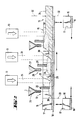
- Fig. 1 shows a model of a possible embodiment, in which semi-continuous composite moldings can be produced in the form of round bars.
- FIG. 2 shows an example of a possible embodiment for the continuous production of composite molded articles with a trapezoidal or rectangular to square cross section.
- silicon granules 1 for example cleaned by acid treatment and present in the desired grain size, are provided in a granulate chamber 2, from which it is dosed into a melting chamber 4 by means of a shaking channel 3.
- the melting chamber 4 consists of a z. B. made of copper, on the inside with, for example, silicon-coated guide ring 5, which has channels 6 in its interior, through which a coolant such as water or cooling gas can be passed. Through an opening 7, the shaking channel 3 protrudes radially into the interior of the melting chamber 4, expediently on a distance corresponding to 65-90% of the chamber radius, and continuously releases the granules transported on this charging path 8.
- These trickle downward and are stored on the surface of a composite molded body section 10 consisting of already bonded granules and which is made of high-temperature-resistant material, such as silicon or silicon carbide, and which is made of high-temperature-resistant material such as silicon or silicon carbide.
- the granulate 11 applied to its surface then reaches the actual melting zone 12, an area on the surface of the rotating composite shaped body section 10 which is irradiated by an energy beam, preferably an electron beam 14, originating from a radiation source 13. that only about 50-70% of the entire end face of the composite molding section is exposed to the radiation.
- the added granules are melted on the surface with the aid of the radiated energy; Grains that are adjacent to one another thereby bond both to one another and to the composite material already produced underneath.
- a layer of granules is generated by the added granules, which extracts heat from the covered composite material, accelerates its crystallization, and is itself brought to an elevated temperature. This stabilizes the binding of the coated granules to one another and to the base.
- the newly applied granulate layer is then melted and bonded analogously.
- the composite molded body grows as the granulate feed progresses. If the rotating punch is lowered in accordance with this growth rate, the melting zone within this melting chamber always remains essentially at the same height. This can also prevent the uppermost growth edge from growing too far into the melting chamber and thereby possibly hindering the rotation.
- round rods obtained in this way are to be joined together, for example to be fused, into larger rod units before the final melting, it has often proven useful to provide extensions or recesses in their end faces and base surfaces, for example pins and pin holes or the like, in order to reconnect them facilitate. This procedure is particularly recommended if the final melting is to be carried out continuously during the semi-continuous production of the partial rods.
- FIG. 1 The arrangement shown in FIG. 1 is surrounded by a recipient, for example made of stainless steel, which is not shown for reasons of clarity and which allows the corresponding working atmosphere to be set and maintained.
- a vacuum of 10- 3- 10- 5 mbar has proven to be particularly advantageous, in which the inevitable high oxygen content, mainly caused by the production and storage of the granules in air, can be significantly reduced.
- the oxide skin covering the granules is destroyed and the oxygen can evaporate in the form of volatile silicon monoxide.
- the composite molded body produced in the method according to the invention can not only be moved out of the melting zone essentially parallel to the charging direction of the silicon granulate, as shown in FIG. 1, that is to say essentially vertically, but also essentially perpendicularly thereto, that is to say essentially horizontally.
- This method is particularly suitable for a layer-by-layer construction of the composite molded body by means of several charging and melting steps connected in series.
- Open, trough-like, z. B. made of graphite or silicon molded elements 15, in which the bottom surface 16 and the two side walls 17 are formed so that they can be lined up to fit a conveyor line 18.
- the trough interior can, for. B. have a rectangular, square, or favorable trapezoidal upward widening cross-section. It is advantageously coated or lined with materials such as silicon or silicon carbide.
- the shaped elements 15 arranged in the conveyor line 18 first move to a first charging station 19, where they receive a first granulate layer 20 of silicon granulate 1 released from a metering device 21. If necessary, this granulate layer 20 can be made more uniform with the aid of a stripper 22 before it is subsequently melted in a first melting zone 23, e.g. B.
- z. B Arrangements are possible in which not the entire form elements 15 are designed to be movable, but in which only the bottom surfaces are moved in the manner of a conveyor belt in the case of stationary side walls. Likewise conceivable are. B. Devices in which, for example, a trough-like conveying element is repeatedly loaded in layers and passed through by a melting zone.
- a comparatively larger amount of energy is required in the first melting station for the surface melting of the silicon granulate, than in the following ones, in which energy is supplied to the material in question by the previously melted and already connected granulate.
- the most suitable amount of energy to be supplied is determined empirically on the basis of the metering speed of the granules, within the range of 20 to 60% of the energy quantum required for the complete melting of the corresponding amount of granules, using preliminary tests.
- each with one radiation source per melting station embodiments are also conceivable in which an adjustable radiation source supplies several melting stations.
- a vacuum of 10-3-10-5 mbar is advantageously set in order, as already explained, to keep the oxygen content of the composite molded body obtained low.
- the inventive method for melting silicon granules in which a composite molding is first formed from the granules before the actual melting step, is particularly suitable for applications in which a continuous flow of molten silicon is required for a long time, such as. B. in the aforementioned production of films or tapes of silicon.
- the use of round rod-shaped preforms as a supply rod during zone drawing is conceivable.
- there are further possible uses for example in crucible pulling according to Czochralski and in the casting of silicon blocks with a columnar structure.
- the known and known to the person skilled in the art, e.g. B. for melting mono- or polycrystalline silicon rods used melting methods, so for example melting with means resistance, induction or radiant heating.
- an amount of 1.2 kg of silicon granules cleaned by acid treatment (grain size 1-15 mm, bulk density approx. 1 g / cm 3 , oxygen content> 10 11 atoms / cm 3 ) was provided and via a shaking channel if necessary, charged into the melting chamber.
- the energy distribution of the electron beam could be adjusted in such a way that when the stamp was rotated, the amount of energy radiated onto each surface element as it passed through the beam path was approximately the same. This also ensured approximately the same melting behavior from the center to the edge of the silicon granules charged on the rotating stamp.
- the punch was first rotated and lowered (about 12 revolutions per minute lowering speed approx. 2 mm / sec) and loaded with silicon granules (pouring speed approx. 10 g / sec) until a bed height of approx. 10 mm was reached. Now the electron beam was switched on and the melting process started. The radiated power during the first revolution was approx. 17 kW; it was then gradually reduced to a value of approximately 12 kW, corresponding to approximately 30% of the power required to completely melt the silicon granules.
- the supply of energy caused that at least partially layer-like areas of melted silicon were formed on the individual granules, which gradually melted in the contact area with adjacent granules. In the end, this resulted in a spatial structure with many cavities made up of grains connected to one another in partial areas, which were removed from the area of action of the electron beam by the rotating movement and at the same time covered with freshly added granules, thereby cooling and freezing them.
- the rate of lowering of the rotating punch and thus of the composite material obtained was set at about 2 mm / sec so that the melting zone, i. H. the zone in which the material is in the melted state always remained in the lower end region of the guide ring, so that the growth edge neither advanced too far into the interior of the melting chamber nor migrated out of it.
- the formed composite body had reached a length of about 200 mm; the addition of granules was stopped and the electron beam was switched off.
- the round rod obtained (density about 1.3 g / cm 3 , oxygen content ⁇ 10 "atoms / cm 3 ) could be removed thanks to its porous structure without the risk of bursting due to thermal stresses and into the melting range of a plant for the production of coarse to single-crystal films from silicon (according to US Pat. No. 4,447,289), where it was finally completely melted from one end by means of an electron beam.
- the stamp was moved back to the starting position so that silicon granulate could be charged into the melting chamber again to produce another round rod.
- this example shows the layer-by-layer production of a preform body which has a rectangular cross section and is moved out of the melting zone in the horizontal direction.
- an 80.20 mm 2 partial area of the trough content was irradiated by means of an electron beam gun until the granules had melted on the surface.
- the trough was set in a horizontal linear movement of approx. 12 mm / sec, so that the melting zone gradually migrated through the entire trough content when the electron beam was at a constant position.
- the power of the electron beam was 16 kW.
- the composite molded body obtained could be completely melted from one end by means of an electron beam, an undisturbed, uniform melt flow being obtained without flaking off fragments.
Applications Claiming Priority (2)
| Application Number | Priority Date | Filing Date | Title |
|---|---|---|---|
| DE3518829 | 1985-05-24 | ||
| DE19853518829 DE3518829A1 (de) | 1985-05-24 | 1985-05-24 | Verfahren zur herstellung von formkoerpern aus siliciumgranulat fuer die erzeugung von siliciumschmelzen |
Publications (3)
| Publication Number | Publication Date |
|---|---|
| EP0203518A2 EP0203518A2 (de) | 1986-12-03 |
| EP0203518A3 EP0203518A3 (en) | 1988-09-21 |
| EP0203518B1 true EP0203518B1 (de) | 1990-08-29 |
Family
ID=6271627
Family Applications (1)
| Application Number | Title | Priority Date | Filing Date |
|---|---|---|---|
| EP86106928A Expired - Lifetime EP0203518B1 (de) | 1985-05-24 | 1986-05-22 | Verfahren zur Herstellung von Formkörpern aus Siliciumgranulat für die Erzeugung von Siliciumschmelzen |
Country Status (6)
| Country | Link |
|---|---|
| US (1) | US4759887A (ja) |
| EP (1) | EP0203518B1 (ja) |
| JP (1) | JPS61270111A (ja) |
| AU (1) | AU584423B2 (ja) |
| DE (2) | DE3518829A1 (ja) |
| ZA (1) | ZA863217B (ja) |
Families Citing this family (21)
| Publication number | Priority date | Publication date | Assignee | Title |
|---|---|---|---|---|
| US5204124A (en) * | 1990-10-09 | 1993-04-20 | Stanley Secretan | Continuous extruded bead object fabrication apparatus |
| DE4307869C2 (de) * | 1993-03-12 | 1996-04-04 | Microparts Gmbh | Mikrostrukturkörper und Verfahren zu deren Herstellung |
| US5534056A (en) * | 1993-10-28 | 1996-07-09 | Manfred R. Kuehnle | Composite media with selectable radiation-transmission properties |
| DE19859288A1 (de) * | 1998-12-22 | 2000-06-29 | Bayer Ag | Agglomeration von Siliciumpulvern |
| US9741881B2 (en) | 2003-04-14 | 2017-08-22 | S'tile | Photovoltaic module including integrated photovoltaic cells |
| US8405183B2 (en) * | 2003-04-14 | 2013-03-26 | S'Tile Pole des Eco-Industries | Semiconductor structure |
| US9493358B2 (en) * | 2003-04-14 | 2016-11-15 | Stile | Photovoltaic module including integrated photovoltaic cells |
| JP4869061B2 (ja) * | 2003-04-14 | 2012-02-01 | セントレ・ナショナル・デ・ラ・レシェルシェ・サイエンティフィーク | 焼結された半導体材料 |
| US8192648B2 (en) * | 2003-04-14 | 2012-06-05 | S'tile | Method for forming a sintered semiconductor material |
| US20090028740A1 (en) * | 2003-04-14 | 2009-01-29 | S'tile | Method for the production of semiconductor granules |
| FR2853562B1 (fr) * | 2003-04-14 | 2006-08-11 | Centre Nat Rech Scient | Procede de fabrication de granules semiconducteurs |
| GB2414231A (en) * | 2004-05-21 | 2005-11-23 | Psimedica Ltd | Porous silicon |
| WO2008057483A2 (en) * | 2006-11-03 | 2008-05-15 | Semlux Technologies, Inc. | Laser conversion of high purity silicon powder to densified garnular forms |
| ES2386602T3 (es) * | 2009-08-25 | 2012-08-23 | Bego Medical Gmbh | Dispositivo y procedimiento para la producción continua generativa |
| EP2289652B2 (de) * | 2009-08-25 | 2022-09-28 | BEGO Medical GmbH | Vorrichtung und Verfahren zur generativen Fertigung |
| DE102011003875A1 (de) * | 2011-02-09 | 2012-08-09 | Wacker Chemie Ag | Verfahren und Vorrichtung zum Dosieren und Verpacken von Polysiliciumbruchstücken sowie Dosier- und Verpackungseinheit |
| DE202011003443U1 (de) | 2011-03-02 | 2011-12-23 | Bego Medical Gmbh | Vorrichtung zur generativen Herstellung dreidimensionaler Bauteile |
| CN103319294B (zh) * | 2013-06-08 | 2015-04-15 | 浙江大学 | 用Bi/Mo/V三组分复合氧化物催化剂合成1,3-丁二烯的方法 |
| DE102015012939A1 (de) * | 2015-10-01 | 2017-04-06 | Kocher-Plastik Maschinenbau Gmbh | Verfahren zur Reduzierung der mikrobiologischen Belastung von Behältererzeugnissen |
| DE102016002777A1 (de) * | 2016-03-09 | 2017-09-14 | Voxeljet Ag | Verfahren und Vorrichtung zum Herstellen von 3D-Formteilen mit Baufeldwerkzeugen |
| WO2024089010A1 (de) * | 2022-10-24 | 2024-05-02 | Eos Gmbh Electro Optical Systems | Verfahren und vorrichtung zur additiven herstellung von elektrochemischen einrichtungen |
Family Cites Families (19)
| Publication number | Priority date | Publication date | Assignee | Title |
|---|---|---|---|---|
| DE1145284B (de) * | 1960-10-11 | 1963-03-14 | Wacker Chemie Gmbh | Verfahren zur Herstellung von Rohren aus hochreinen Stoffen |
| FR1427925A (fr) * | 1964-12-29 | 1966-02-11 | Electro Refractaire | Procédé et appareil pour la fusion et la solidification continues des réfractaires électrofondus |
| FR1445684A (fr) * | 1965-06-03 | 1966-07-15 | Commissariat Energie Atomique | Dispositif de coulée continue de matériaux réfractaires |
| US3724977A (en) * | 1971-04-29 | 1973-04-03 | Nat Standard Co | Reducing and sintering furnace means |
| US3744946A (en) * | 1971-10-15 | 1973-07-10 | Nat Standard Co | Apparatus for fabricating continuous elongated components |
| US4005956A (en) * | 1973-04-11 | 1977-02-01 | Inoue-Japax Research Incorporated | Powder activation and integrated powder metallurgy system |
| US4012213A (en) * | 1973-06-14 | 1977-03-15 | Arthur D. Little, Inc. | Apparatus for forming refractory fibers |
| US4116598A (en) * | 1975-03-04 | 1978-09-26 | Fizichesky Institut Imeni P.N. Lebedeva Akademii Nauk Sssr | Apparatus for producing high-melting-metal-oxide-based crystalline materials |
| US4218410A (en) * | 1975-06-28 | 1980-08-19 | Leybold-Heraeus Gmbh & Co. Kg | Method for the production of high-purity metal powder by means of electron beam heating |
| DE2528999C2 (de) * | 1975-06-28 | 1984-08-23 | Leybold-Heraeus GmbH, 5000 Köln | Verfahren und Vorrichtung zur Herstellung von hochreinem Metallpulver mittels Elektronenstrahlbeheizung |
| DE2638270C2 (de) * | 1976-08-25 | 1983-01-27 | Wacker-Chemitronic Gesellschaft für Elektronik-Grundstoffe mbH, 8263 Burghausen | Verfahren zur Herstellung großflächiger, freitragender Platten aus Silicium |
| DE2745247C3 (de) * | 1977-10-07 | 1980-03-13 | Wacker-Chemitronic Gesellschaft Fuer Elektronik-Grundstoffe Mbh, 8263 Burghausen | Verfahren und Vorrichtung zur semikontinuierlichen Herstellung von Siliciumformkörpern |
| DE2821481C2 (de) * | 1978-05-17 | 1985-12-05 | Wacker-Chemitronic Gesellschaft für Elektronik-Grundstoffe mbH, 8263 Burghausen | Vorrichtung zum Ziehen von hochreinen Halbleiterstäben aus der Schmelze |
| US4358416A (en) * | 1980-12-04 | 1982-11-09 | Olin Corporation | Apparatus and process for cooling and solidifying molten material being electromagnetically cast |
| DE3049376A1 (de) * | 1980-12-29 | 1982-07-29 | Heliotronic Forschungs- und Entwicklungsgesellschaft für Solarzellen-Grundstoffe mbH, 8263 Burghausen | Verfahren zur herstellung vertikaler pn-uebergaenge beim ziehen von siliciumscheiben aus einer siliciumschmelze |
| DE3132776A1 (de) * | 1981-08-19 | 1983-03-03 | Heliotronic Gmbh | Verfahren zur herstellung grob- bis einkristalliner folien aus halbleitermaterial |
| US4410471A (en) * | 1981-11-23 | 1983-10-18 | Motorola, Inc. | Ribbon-to-ribbon conversion with shaped molten zone |
| JPS59129702A (ja) * | 1983-01-13 | 1984-07-26 | Tanaka Kikinzoku Kogyo Kk | 貴金属含有合金の粉末製造法 |
| US4572812A (en) * | 1984-08-13 | 1986-02-25 | The United States Of America As Represented By The Secretary Of Energy | Method and apparatus for casting conductive and semiconductive materials |
-
1985
- 1985-05-24 DE DE19853518829 patent/DE3518829A1/de not_active Withdrawn
-
1986
- 1986-04-25 JP JP61094996A patent/JPS61270111A/ja active Granted
- 1986-04-30 ZA ZA863217A patent/ZA863217B/xx unknown
- 1986-05-12 US US06/862,006 patent/US4759887A/en not_active Expired - Fee Related
- 1986-05-22 EP EP86106928A patent/EP0203518B1/de not_active Expired - Lifetime
- 1986-05-22 DE DE8686106928T patent/DE3673694D1/de not_active Expired - Fee Related
- 1986-05-23 AU AU57854/86A patent/AU584423B2/en not_active Ceased
Also Published As
| Publication number | Publication date |
|---|---|
| JPS61270111A (ja) | 1986-11-29 |
| EP0203518A2 (de) | 1986-12-03 |
| EP0203518A3 (en) | 1988-09-21 |
| DE3518829A1 (de) | 1986-11-27 |
| DE3673694D1 (de) | 1990-10-04 |
| ZA863217B (en) | 1986-12-30 |
| AU584423B2 (en) | 1989-05-25 |
| AU5785486A (en) | 1986-11-27 |
| US4759887A (en) | 1988-07-26 |
| JPH027881B2 (ja) | 1990-02-21 |
Similar Documents
| Publication | Publication Date | Title |
|---|---|---|
| EP0203518B1 (de) | Verfahren zur Herstellung von Formkörpern aus Siliciumgranulat für die Erzeugung von Siliciumschmelzen | |
| EP2552675B1 (de) | Vorrichtung und verfahren zum herstellen dreidimensionaler modelle | |
| EP1192040B1 (de) | Verfahren und vorrichtung zum herstellen eines dreidimensionalen objekts | |
| EP0911142B1 (de) | Verwendung eines Polyamids 12 für selektives Laser-Sintern und Polyamid 12 Pulver | |
| EP1539465B1 (de) | Verfahren zum herstellen eines dreidimensionalen formkörpers | |
| DE19681075B4 (de) | Verfahren zur Herstellung von Halbleiterteilchen und Vorrichtung zur Durchführung des Verfahrens | |
| EP0021385B1 (de) | Verfahren zur Herstellung von Siliciumstäben | |
| DE60003131T2 (de) | Vorrichtung für die Herstellung polykristalliner Siliziumfolien und Herstellungsverfahren das sie benutzt | |
| DE4418401C1 (de) | Verfahren und Vorrichtung zur Herstellung von Platten aus Quarzglas | |
| EP0462494A1 (de) | Verfahren und Vorrichtung zum Giessen von Siliciumblöcken mit Kolumnarstruktur als Grundmaterial für Solarzellen | |
| DE3132776A1 (de) | Verfahren zur herstellung grob- bis einkristalliner folien aus halbleitermaterial | |
| DE3836392C2 (de) | Verfahren und Vorrichtung zur Herstellung rohrförmiger keramischer Körper | |
| DE4216519A1 (de) | Fliesszonenverfahren zur herstellung von monokristallinem silicium aus teilchenfoermigem silicium | |
| DE2451921A1 (de) | Verfahren und integrierte ofenanlage zum kontinuierlichen metallgiessen | |
| DE2903061A1 (de) | Verfahren zur herstellung grosskristalliner vorzugsorientierter siliciumfolien | |
| EP0258818A2 (de) | Verfahren zum Aufschmelzen von in einen Schmelztiegel chargiertem Siliciumpulver und Schmelztiegel zur Durchführung des Verfahrens | |
| DE4323793A1 (de) | Verfahren zur Herstellung von Stäben oder Blöcken aus beim Erstarren sich ausdehnendem Halbleitermaterial durch Kristallisieren einer aus Granulat erzeugten Schmelze sowie Vorrichtung zu seiner Durchführung | |
| DE3531610A1 (de) | Verfahren und vorrichtung zur herstellung von siliciumstaeben | |
| DE10204178A1 (de) | Verfahren und Vorrichtung zum Herstellen eines Einkristalls aus Halbleitermaterial | |
| EP0243805A2 (de) | Verfahren zur Herstellung von Formkörpern aus Granulat auf der Basis von Silicium, Germanium oder Mischkristallen dieser Elemente | |
| EP0095707A1 (de) | Verfahren zum Herstellen polykristalliner, für nachfolgendes Zonenschmelzen geeigneter Siliciumstäbe | |
| DE1218412B (de) | Verfahren zum Herstellen von einkristallinem Halbleitermaterial | |
| EP0027477A1 (de) | Verfahren und Anlage zum Herstellen von Hohlblocksteinen mit Kunststoff-Füllung | |
| DE19724461A1 (de) | Verfahren zur Herstellung von verbackungsfreien Hydroxipivalinsäureneopentylglykolester- Granulaten | |
| DE19781525B4 (de) | Verfahren zur Herstellung von Granalien eines thermolabilen Materials und Vorrichtung zur Durchführung dieses Verfahrens |
Legal Events
| Date | Code | Title | Description |
|---|---|---|---|
| PUAI | Public reference made under article 153(3) epc to a published international application that has entered the european phase |
Free format text: ORIGINAL CODE: 0009012 |
|
| 17P | Request for examination filed |
Effective date: 19860522 |
|
| AK | Designated contracting states |
Kind code of ref document: A2 Designated state(s): AT BE CH DE FR GB IT LI NL |
|
| PUAL | Search report despatched |
Free format text: ORIGINAL CODE: 0009013 |
|
| AK | Designated contracting states |
Kind code of ref document: A3 Designated state(s): AT BE CH DE FR GB IT LI NL |
|
| 17Q | First examination report despatched |
Effective date: 19891106 |
|
| GRAA | (expected) grant |
Free format text: ORIGINAL CODE: 0009210 |
|
| AK | Designated contracting states |
Kind code of ref document: B1 Designated state(s): DE IT |
|
| REF | Corresponds to: |
Ref document number: 3673694 Country of ref document: DE Date of ref document: 19901004 |
|
| ITF | It: translation for a ep patent filed |
Owner name: SOCIETA' ITALIANA BREVETTI S.P.A. |
|
| EN | Fr: translation not filed | ||
| PLBE | No opposition filed within time limit |
Free format text: ORIGINAL CODE: 0009261 |
|
| STAA | Information on the status of an ep patent application or granted ep patent |
Free format text: STATUS: NO OPPOSITION FILED WITHIN TIME LIMIT |
|
| 26N | No opposition filed | ||
| PG25 | Lapsed in a contracting state [announced via postgrant information from national office to epo] |
Ref country code: DE Effective date: 19920303 |
|
| PG25 | Lapsed in a contracting state [announced via postgrant information from national office to epo] |
Ref country code: IT Free format text: LAPSE BECAUSE OF NON-PAYMENT OF DUE FEES;WARNING: LAPSES OF ITALIAN PATENTS WITH EFFECTIVE DATE BEFORE 2007 MAY HAVE OCCURRED AT ANY TIME BEFORE 2007. THE CORRECT EFFECTIVE DATE MAY BE DIFFERENT FROM THE ONE RECORDED. Effective date: 20050522 |