EP0201769A2 - Schlauchtrommel für Absaugschläuche - Google Patents
Schlauchtrommel für Absaugschläuche Download PDFInfo
- Publication number
- EP0201769A2 EP0201769A2 EP19860105560 EP86105560A EP0201769A2 EP 0201769 A2 EP0201769 A2 EP 0201769A2 EP 19860105560 EP19860105560 EP 19860105560 EP 86105560 A EP86105560 A EP 86105560A EP 0201769 A2 EP0201769 A2 EP 0201769A2
- Authority
- EP
- European Patent Office
- Prior art keywords
- drum body
- hose reel
- hose
- reel according
- suction
- Prior art date
- Legal status (The legal status is an assumption and is not a legal conclusion. Google has not performed a legal analysis and makes no representation as to the accuracy of the status listed.)
- Granted
Links
- 239000004033 plastic Substances 0.000 claims description 4
- 239000007789 gas Substances 0.000 claims description 3
- 238000005096 rolling process Methods 0.000 abstract 1
- 238000004804 winding Methods 0.000 description 7
- 238000004519 manufacturing process Methods 0.000 description 2
- 230000006978 adaptation Effects 0.000 description 1
- 238000005452 bending Methods 0.000 description 1
- 229920001821 foam rubber Polymers 0.000 description 1
- 231100000206 health hazard Toxicity 0.000 description 1
- 238000002347 injection Methods 0.000 description 1
- 239000007924 injection Substances 0.000 description 1
- 239000002184 metal Substances 0.000 description 1
- 239000002985 plastic film Substances 0.000 description 1
- 229920006255 plastic film Polymers 0.000 description 1
Images

Classifications
-
- B—PERFORMING OPERATIONS; TRANSPORTING
- B08—CLEANING
- B08B—CLEANING IN GENERAL; PREVENTION OF FOULING IN GENERAL
- B08B15/00—Preventing escape of dirt or fumes from the area where they are produced; Collecting or removing dirt or fumes from that area
- B08B15/002—Preventing escape of dirt or fumes from the area where they are produced; Collecting or removing dirt or fumes from that area using a central suction system, e.g. for collecting exhaust gases in workshops
-
- B—PERFORMING OPERATIONS; TRANSPORTING
- B65—CONVEYING; PACKING; STORING; HANDLING THIN OR FILAMENTARY MATERIAL
- B65H—HANDLING THIN OR FILAMENTARY MATERIAL, e.g. SHEETS, WEBS, CABLES
- B65H75/00—Storing webs, tapes, or filamentary material, e.g. on reels
- B65H75/02—Cores, formers, supports, or holders for coiled, wound, or folded material, e.g. reels, spindles, bobbins, cop tubes, cans, mandrels or chucks
- B65H75/18—Constructional details
- B65H75/20—Skeleton construction, e.g. formed of wire
-
- B—PERFORMING OPERATIONS; TRANSPORTING
- B65—CONVEYING; PACKING; STORING; HANDLING THIN OR FILAMENTARY MATERIAL
- B65H—HANDLING THIN OR FILAMENTARY MATERIAL, e.g. SHEETS, WEBS, CABLES
- B65H75/00—Storing webs, tapes, or filamentary material, e.g. on reels
- B65H75/02—Cores, formers, supports, or holders for coiled, wound, or folded material, e.g. reels, spindles, bobbins, cop tubes, cans, mandrels or chucks
- B65H75/34—Cores, formers, supports, or holders for coiled, wound, or folded material, e.g. reels, spindles, bobbins, cop tubes, cans, mandrels or chucks specially adapted or mounted for storing and repeatedly paying-out and re-storing lengths of material provided for particular purposes, e.g. anchored hoses, power cables
- B65H75/38—Cores, formers, supports, or holders for coiled, wound, or folded material, e.g. reels, spindles, bobbins, cop tubes, cans, mandrels or chucks specially adapted or mounted for storing and repeatedly paying-out and re-storing lengths of material provided for particular purposes, e.g. anchored hoses, power cables involving the use of a core or former internal to, and supporting, a stored package of material
-
- B—PERFORMING OPERATIONS; TRANSPORTING
- B65—CONVEYING; PACKING; STORING; HANDLING THIN OR FILAMENTARY MATERIAL
- B65H—HANDLING THIN OR FILAMENTARY MATERIAL, e.g. SHEETS, WEBS, CABLES
- B65H2701/00—Handled material; Storage means
- B65H2701/30—Handled filamentary material
- B65H2701/33—Hollow or hose-like material
Definitions
- the invention relates to a hose drum for suction hoses according to the preamble of claim 1.
- suction hoses When repairing and servicing motor vehicles, the exhaust gases that occur must be extracted using suction hoses. So that these suction hoses do not interfere when not in use, it is known to roll them up on hose reels mounted above the workplace. These known hose drums have a smooth cylindrical drum shell, which, however, does not guarantee that the suction hose is rolled up close to one another. Rather, gaps can form between the hose turns or the hose rides open and is thereby crushed and damaged. This creates cracks in the hose through which the exhaust gases can escape and thus pose a health hazard to the workplace.
- the object of the present invention is therefore to create a hose reel of the type mentioned in the introduction, in which when the suction hose is rolled up, the windings of the hose are guided close to one another and are simple and efficient can be produced socially.
- the structure of wires allows economical production and perfect adaptation to the desired outer shape, resulting in a particularly stable structure.
- a helically wound guide basket is used, through which the hose is guided in a continuous curve from an opening of the drum jacket to the suction line in the axis of the drum body.
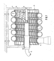
- a hose drum 2 is rotatably mounted on a frame 1.
- the lateral surface 3 has part-circular grooves 4, which run around the lateral surface 3 in a helical manner and to which the windings of the suction hose 5 closely abut.
- a plug-in motor 7 arranged in its axis, the axis 8 of which is fixedly connected to the frame 1 and the circumferential jacket of which drives the drum body via pins 9.
- a sleeve 10 is rotatably mounted in the frame 1, to which a suction line 11 is connected. This leads to a suction device, not shown.
- the sleeve 10 is connected to one end of the suction hose 5, which is guided into the interior of the drum body via an opening 12 in the lateral surface 3.
- a helically wound guide basket 13 is provided leading inwards from the lateral surface 3, which enables the suction hose to be continuously introduced to the sleeve 10.
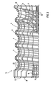
- the drum body 6 is formed from wires which can be bent into the desired shape in a particularly economical manner and ensure a stable structure of the drum body.
- drum body 6 consists of a basket 14 and the associated axle sleeves 15 and 16.
- Outer basket 14 consists of axially extending wires 17 which are bent from a straight wire in the central region into the partially circular grooves. Your ends will be over Turned 90 ° and later form the end faces Reel body 6. The helical course of the grooves over the outer surface 3 can be easily achieved by bending the wires at changing intervals from their ends.
- the two axle sleeves 15 and 16 are also formed from axially extending wires 19 and 20, the ends of which are bent at right angles and extend in the end faces 18 between the ends of the wires 17 from the outer basket 14. (See Fig. 3) Both the wire ends 17 and 19 are welded together in the end face 18 by wire rings 21.
- the outer surface 3 is also wrapped helically by a wire 22, so that the drum body 6 is extremely stable.
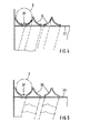
- guide elements for the suction hose 5 in the form of plastic profiles 24 are riveted onto a cylindrical drum jacket 23 made of sheet metal, which run around the drum jacket 23 in a helical manner and thus again form helical grooves 25.
- plastic profiles can also be designed as limited segments.
- helical wire brackets 26 can also be fastened on the drum jacket 23 as guide elements, which again form grooves 27 for the suction hose 5.
- a sleeve made of foamed plastic, such as foam rubber, can also be attached, which is either els flat mat with the sloping Grooves 25 is provided or the grooves form when winding the suction hose 5.
Landscapes
- Storing, Repeated Paying-Out, And Re-Storing Of Elongated Articles (AREA)
- External Artificial Organs (AREA)
- Storage Of Web-Like Or Filamentary Materials (AREA)
- Rigid Pipes And Flexible Pipes (AREA)
Abstract
Description
- Die Erfindung bezieht sich auf eine Schlauchtrommel für Absaugschläuche gemäß Oberbegriff von Anspruch 1.
- Bei der Reparatur und beim Kundendienst von Kraftfahrzeugen müssen die auftretenden Abgase mittels Absaugschläuchen abgesaugt werden. Damit diese Absaugschläuche beim Nichtgebrauch nicht stören ist es bekannt, sie auf über dem Arbeitsplatz angebrachten Schlauchtrommeln aufzurollen. Diese bekannten Schlauchtrommeln weisen einen glatt zylindrischen Trommelmantel auf, bei dem jedoch nicht gewährleistet ist, daß der Absaugschlauch eng aneinanderliegend aufgerollt wird. Zwischen den Schlauchwindungen können sich vielmehr Zwischenräume bilden oder der Schlauch reitet auf und wird dabei gequetscht und beschädigt. Dabei bilden sich Risse im Schlauch, durch die die Abgase austreten können und somit eine gesundheitliche Gefahr für den Arbeitsplatz darstellen.
- Zur Erzwingung einer einwandfreien Aufwicklung sind auch automatische Schlauchführungen bekannt, die jedoch die Schlauchtrommel erheblich verteuern.
- Aufgabe der vorliegenaen Erfinaung ist daher die Schaffung einer Schlauchtrommel der eingangs genannten Art, bei der beim Aufrollen des Absaugschlauches dessen Windungen eng aneinanderliegend geführt sind und die sich auf eine einfache und wirtschaftliche Art herstellen lässt.
- Diese Aufgabe wird erfindungsgemäß durch die im Kennzeichnenden Teil des Ansprucns 1 angegebenen Merkmale gelöst.
- Damit ist beim Aufrollen gewährleistet, daß sich der Absaugschlauch Windung neben Windung um den Trommelmantel legt und nicht gequetscht oder beschädigt wird.
- In den Unteransprüchen sind besonders vorteilhafte Ausführungsformen des Trommelkörpers gekennzeichnet.
- Der Aufbau aus Drähten erlaubt eine wirtschaftliche Fertigung und einwandfreie Anpassung an die gewünschte Außenform, wobei sich ein besonders stabiler Aufbau ergibt.
- Für die Einführung des einen Schlauchendes in die Mitte des Trommelkörpers dient ein schraubenförmig gewundener Führungskorb, durch den der Schlauch in einer kontinuierlichen Krümmung von einer Öffnung des Trommelmantels zur Absaugleitung in der Achse des Trommelkörpers geführt wird.
- Die Verwendung eines Außenläufermotors in Forn eines in der Achse des Trommelkörpers angeordneten Steckmotors ergibt zusätzlich einen einfachen Aufbau und eine preiswerte Fertigung für den Antrieb des Trommelkörpers.
- Im folgenden sind Ausführungsbeispiele der Erfindung unter Bezugnahme auf die Zeichnungen näher beschrieben.
- Es zeiger:
- Fig. 1 Längsschnitt durch ein 1. Ausführungsbeispiel einer Schlauchtrommel
- Fig. 2 Umrißlinie des halben Trommelkörpers gemäß Fig. 1
- Fig. 3 Trommelkörper gemäß Fig. 1 von der Seite
- Fig. 4 Teilschnitt durch ein 2. Ausführungsbeispiel des Trommelkörpers.
- Fig. 5 Teilechnitt durch ein 3. Ausführungsbeispiel des Trommelkörpers.
- Wie Fig. 1 zeigt, ist an einem Rahmen 1 eine Schlauchtrommel 2 drehbar gelagert. Die Mantelfläche 3 weist teilkreisförmige Rillen 4 auf, die die Mantelfläche 3 schraubenförmig umlaufen und an die sich die Windungen des Absaugschlauches 5 eng anlegen.
- Zum antrieb des Trommelkörpers 6 dient ein in seiner Achse angeordneter Steckmotor 7, dessen Achse 8 fest mit dem Rahmen 1 verbunden ist und dessen umlaufender Mantel über Zapfen 9 den Trommelkörper antreibt.
- Auf der gegenüberliegenden Seite des Trommelkörpers ist im Rahmen 1 eine Hülse 10 drehbar gelagert, an der eine Absaugleitung 11 angeschlossen ist. Diese führt zu einer nicht dargestellten Absaugvorrichtung. Im Innern von Trommelkörper 6 ist die Hülse 10 mit einem Ende des Absaugschlauches 5 verbunden, der über eine Offnung 12 in der Mantelfläche 3 ins Innere des Trommelkörpers geführt wird. Um auch hier ein Abknicken des Absaugschlauches zu vermeiden, ist von der Mantelfläche 3 nach innen führend ein schraubenförmig gewundener Führungskorb 13 vorgesehen, der eine kontinuierliche Einleitung des Absaugschlauches zur Hülse 10 ermöglicht.
- Wie besonders die Fig. 2 und 3 zeigen, ist der Trommelkörper 6 aus Drähten gebildet, die sich auf besonders wirtschaftliche Weise in die gewünschte Form biegen lassen und einen stabilen Aufbau des Trommelkörpers gewährleisten.
- Wie Fig. 2 zeigt, besteht der Trommelkörper 6 aus einem Ausenkorb 14 und den damit verbundenen Achsenhülsen 15 und 16.
- Außenkorb 14 besteht aus achsial verlaufenden Drähten 17, die aus einem geraden Draht im mittleren Bereich in die teilkreisförmigen hillen gebogen werden. Ihre Enden werden um 90° abgebogen und bilden später die StirnseitenTrommelkörpers 6. Der schraubenförmige Verlauf der Rillen über die Mantelfläche 3 läßt eich leicht erzielen, indem die Drähte in sich ändernden Abständen von ihren Enden abgebogen werden.

- Die beiden Achshülsen 15 und 16 sind ebenfalls aus achsial verlaufenden Drähten 19 und 20 gebildet, deren rechtwinklig abgebogene Enden sich in den Stirnseiten 18 zwischen die Enden der Drähte 17 von Außenkorb 14 erstrecken. (Siehe Fig. 3) Sowohl die Drahtenden 17 als auch 19 sind in der Stirnseite 18 durch Drahtringe 21 miteinander verschweißt.
- Die Mantelfläche 3 ist außerdem durch einen Draht 22 schraubenförmig umwickelt, so daß sich ein außerordentlich stabiler Aufbau des Trommelkörpers 6 ergibt.
- Bei einem weiteren Ausführungsbeispiel der Erfindung gemäß Fig. 4 sind auf einem zylindrischen Trommelmantel 23 aus Blech Führungselemente fur den Absaugschlauch 5 in Form von Kunststoffprofilen 24 aufgenietet, die den Trommel - mantel 23 schraubenförmig umlaufen und damit wieder schraubenförmig verlaufende Rillen 25 bilden.
- Diese Kunststoffprofile können auch als begrenzte Segmente ausgeführt sein.
- Wie Fig. 5 zeigt, lassen sich auf dem Trommelmantel 23 auch schraubenförmig verlaufende Drahtbügel 26 als Führungselemente befestigen, die wieder Rillen 27 für den Absaugschlauch 5 bilden.
- Auf dem Troommelmantel 23 läßt sich auch eine Hülse aus geschäumtem Kunststoff, wie z.B. Schaumgummi befestigen, die entweder bereits els flache Matte mit den schräg verlaufenden Rillen 25 versehen ist oder deren Rillen sich beim Aufwickeln des Absaugschlauchs 5 bilden.
- Ebenso ist es möglich, eine mit Rillen 25 versehene T'ülse aus einer Kunststoff-Folie mit dem Trommelmantel 23 zu verbinden oder diesen in einer Spritzform mit dieser Hülse zu umspritzen.
Claims (12)
Priority Applications (1)
| Application Number | Priority Date | Filing Date | Title |
|---|---|---|---|
| AT86105560T ATE60565T1 (de) | 1985-05-11 | 1986-04-22 | Schlauchtrommel fuer absaugschlaeuche. |
Applications Claiming Priority (2)
| Application Number | Priority Date | Filing Date | Title |
|---|---|---|---|
| DE19853517150 DE3517150A1 (de) | 1985-05-11 | 1985-05-11 | Schlauchtrommel fuer absaugschlaeuche |
| DE3517150 | 1985-05-11 |
Publications (3)
| Publication Number | Publication Date |
|---|---|
| EP0201769A2 true EP0201769A2 (de) | 1986-11-20 |
| EP0201769A3 EP0201769A3 (en) | 1987-12-09 |
| EP0201769B1 EP0201769B1 (de) | 1991-01-30 |
Family
ID=6270588
Family Applications (1)
| Application Number | Title | Priority Date | Filing Date |
|---|---|---|---|
| EP86105560A Expired - Lifetime EP0201769B1 (de) | 1985-05-11 | 1986-04-22 | Schlauchtrommel für Absaugschläuche |
Country Status (4)
| Country | Link |
|---|---|
| EP (1) | EP0201769B1 (de) |
| JP (1) | JPS6256273A (de) |
| AT (1) | ATE60565T1 (de) |
| DE (2) | DE3517150A1 (de) |
Cited By (1)
| Publication number | Priority date | Publication date | Assignee | Title |
|---|---|---|---|---|
| EP0529150A1 (de) * | 1991-08-27 | 1993-03-03 | Carsten Bardehle | Saugschlauchtrommel |
Families Citing this family (1)
| Publication number | Priority date | Publication date | Assignee | Title |
|---|---|---|---|---|
| CN110014011B (zh) * | 2019-04-20 | 2020-07-24 | 杭州富阳和翔模具有限公司 | 一种用于收集粉尘的可自动分类的多功能设备 |
Family Cites Families (7)
| Publication number | Priority date | Publication date | Assignee | Title |
|---|---|---|---|---|
| DE492617C (de) * | 1928-11-01 | 1930-02-26 | Gustav Menzel | Schlauchhaspel mit selbsttaetiger Aufwickelvorrichtung |
| US2478540A (en) * | 1948-05-17 | 1949-08-09 | Universal Properties Inc | Take-up hose reeling equipment |
| US3011201A (en) * | 1959-03-31 | 1961-12-05 | Cymara Hermann Karl | Vacuum dust pan and reel |
| GB1138393A (en) * | 1966-02-01 | 1969-01-01 | Gkn Group Services Ltd | Improvements relating to reels, drums, and the like for holding or containing an article or articles |
| GB1104000A (en) * | 1966-02-24 | 1968-02-21 | Andrew George Philip Haselden | Improvements in or relating to hose reels |
| SE353242B (de) * | 1972-04-18 | 1973-01-29 | B Nederman | |
| DE2823024A1 (de) * | 1978-05-26 | 1979-11-29 | Grimm Willi J | Wasserschlauchtrommel |
-
1985
- 1985-05-11 DE DE19853517150 patent/DE3517150A1/de not_active Withdrawn
-
1986
- 1986-04-22 AT AT86105560T patent/ATE60565T1/de not_active IP Right Cessation
- 1986-04-22 EP EP86105560A patent/EP0201769B1/de not_active Expired - Lifetime
- 1986-04-22 DE DE8686105560T patent/DE3677252D1/de not_active Expired - Lifetime
- 1986-05-09 JP JP61104716A patent/JPS6256273A/ja active Pending
Cited By (1)
| Publication number | Priority date | Publication date | Assignee | Title |
|---|---|---|---|---|
| EP0529150A1 (de) * | 1991-08-27 | 1993-03-03 | Carsten Bardehle | Saugschlauchtrommel |
Also Published As
| Publication number | Publication date |
|---|---|
| DE3517150A1 (de) | 1986-11-13 |
| DE3677252D1 (de) | 1991-03-07 |
| JPS6256273A (ja) | 1987-03-11 |
| EP0201769A3 (en) | 1987-12-09 |
| ATE60565T1 (de) | 1991-02-15 |
| EP0201769B1 (de) | 1991-01-30 |
Similar Documents
| Publication | Publication Date | Title |
|---|---|---|
| DE2357047C2 (de) | Verfahren zum Kürzen einer Bewehrung vor dem Befestigen einer flexiblen Leitung an einem steifen Kupplungsstück | |
| DE3145122C2 (de) | Vorrichtung zum Herstellen eines Rohres od. dgl. aus einem stranggepreßten thermoplastischen Kunststoffprofil | |
| DE2758463B2 (de) | Endoskop mit flexiblem Endabschnitt und Krümmungseinrichtung dafür | |
| DE2711236A1 (de) | Verfahren und vorrichtung zur herstellung eines rohres | |
| DE2330799C2 (de) | Vorgefertigte, demontierbare isolierende Rohrverkleidung | |
| DE2838305C2 (de) | Verfahren zur Herstellung eines Rohrverbinders aus verstärktem Kunstharz | |
| DE1966673B2 (de) | Vorrichtung zur Herstellung eines Bewehrungskäfigs für Spannbetonrohre | |
| DE60122653T2 (de) | Entkrangelvorrichtung für Kabel eines Schwimmbeckenreinigungsroboters | |
| EP0201769A2 (de) | Schlauchtrommel für Absaugschläuche | |
| WO1987001878A1 (fr) | Dispositif pour inserer ulterieurement des cables dans des gaines prevues a cet effet | |
| DE3001472C2 (de) | Verfahren und Vorrichtung zum Vereinigen von Schraubenwendeln zu einem Schraubenwendel-Transportband | |
| DE3606767C1 (de) | Flexibler geschlossener Rohrverbund | |
| EP0251029A1 (de) | Verfahren zum Herstellen eines flachen Spulenbandes | |
| DE19859859A1 (de) | Modulgerüstrohr | |
| DE2501935C2 (de) | Dauer- oder wasserwellwickel | |
| DE19624984A1 (de) | Rohr mit axialem Schlitz | |
| DE1613011A1 (de) | Stator eines dauermagnetisch erregten Kleinmotors | |
| DE3000335C2 (de) | Entmagnetisierungsspule | |
| DE4318608B4 (de) | Verfahren und Vorrichtung zur Herstellung eines Abzugrohrs aus faserverstärktem Kunststoff, insbesondere für einen Abzug zur Abführung chemisch aggressiver Dämpfe | |
| DE19504674B4 (de) | Auf stabförmiges Material aufsetzbares Handgriffelement aus Kunststoff, insbesondere für elektrische Kabeltrommeln | |
| DE2417219C3 (de) | Ringwellrohr mit Verstärkungsringen | |
| DE164378C (de) | ||
| DE649494C (de) | Verfahren zum Herstellen auswechselbarer Belaege von Kautschukwalzen fuer Wringmaschinen o. dgl. | |
| DE3541087C2 (de) | ||
| DE1286201B (de) | Verfahren zur Herstellung von zylindrischen Transformatorenkernen groesserer Kernhoehe aus Blechbaendern oder Tafelblechen und Vorrichtung zur Durchfuehrung des Verfahrens |
Legal Events
| Date | Code | Title | Description |
|---|---|---|---|
| PUAI | Public reference made under article 153(3) epc to a published international application that has entered the european phase |
Free format text: ORIGINAL CODE: 0009012 |
|
| AK | Designated contracting states |
Kind code of ref document: A2 Designated state(s): AT CH DE FR GB IT LI NL SE |
|
| PUAL | Search report despatched |
Free format text: ORIGINAL CODE: 0009013 |
|
| AK | Designated contracting states |
Kind code of ref document: A3 Designated state(s): AT CH DE FR GB IT LI NL SE |
|
| 17P | Request for examination filed |
Effective date: 19880415 |
|
| 17Q | First examination report despatched |
Effective date: 19891107 |
|
| RAP3 | Party data changed (applicant data changed or rights of an application transferred) |
Owner name: CHRISTIAN O. GRUHL GMBH & CO. |
|
| RIN1 | Information on inventor provided before grant (corrected) |
Inventor name: GRUHL, CHRISTIAN O. |
|
| GRAA | (expected) grant |
Free format text: ORIGINAL CODE: 0009210 |
|
| AK | Designated contracting states |
Kind code of ref document: B1 Designated state(s): AT CH DE FR GB IT LI NL SE |
|
| PG25 | Lapsed in a contracting state [announced via postgrant information from national office to epo] |
Ref country code: NL Effective date: 19910130 Ref country code: IT Free format text: LAPSE BECAUSE OF FAILURE TO SUBMIT A TRANSLATION OF THE DESCRIPTION OR TO PAY THE FEE WITHIN THE PRE;WARNING: LAPSES OF ITALIAN PATENTS WITH EFFECTIVE DATE BEFORE 2007 MAY HAVE OCCURRED AT ANY TIME BEFORE 2007. THE CORRECT EFFECTIVE DATE MAY BE DIFFERENT FROM THE ONE RECORDED.SCRIBED TIME-LIMIT Effective date: 19910130 Ref country code: FR Effective date: 19910130 Ref country code: SE Effective date: 19910130 Ref country code: GB Effective date: 19910130 |
|
| REF | Corresponds to: |
Ref document number: 60565 Country of ref document: AT Date of ref document: 19910215 Kind code of ref document: T |
|
| REF | Corresponds to: |
Ref document number: 3677252 Country of ref document: DE Date of ref document: 19910307 |
|
| PG25 | Lapsed in a contracting state [announced via postgrant information from national office to epo] |
Ref country code: AT Effective date: 19910422 |
|
| PG25 | Lapsed in a contracting state [announced via postgrant information from national office to epo] |
Ref country code: LI Effective date: 19910430 Ref country code: CH Effective date: 19910430 |
|
| EN | Fr: translation not filed | ||
| NLV1 | Nl: lapsed or annulled due to failure to fulfill the requirements of art. 29p and 29m of the patents act | ||
| GBV | Gb: ep patent (uk) treated as always having been void in accordance with gb section 77(7)/1977 [no translation filed] | ||
| PLBE | No opposition filed within time limit |
Free format text: ORIGINAL CODE: 0009261 |
|
| STAA | Information on the status of an ep patent application or granted ep patent |
Free format text: STATUS: NO OPPOSITION FILED WITHIN TIME LIMIT |
|
| REG | Reference to a national code |
Ref country code: CH Ref legal event code: PL |
|
| 26N | No opposition filed | ||
| PGFP | Annual fee paid to national office [announced via postgrant information from national office to epo] |
Ref country code: DE Payment date: 19970916 Year of fee payment: 12 |
|
| PG25 | Lapsed in a contracting state [announced via postgrant information from national office to epo] |
Ref country code: DE Free format text: LAPSE BECAUSE OF NON-PAYMENT OF DUE FEES Effective date: 19980430 |