EP0200993B1 - Dispositif d'enfichage pour la connexion d'appareils électriques, de préférence de disjoncteurs - Google Patents
Dispositif d'enfichage pour la connexion d'appareils électriques, de préférence de disjoncteurs Download PDFInfo
- Publication number
- EP0200993B1 EP0200993B1 EP86105591A EP86105591A EP0200993B1 EP 0200993 B1 EP0200993 B1 EP 0200993B1 EP 86105591 A EP86105591 A EP 86105591A EP 86105591 A EP86105591 A EP 86105591A EP 0200993 B1 EP0200993 B1 EP 0200993B1
- Authority
- EP
- European Patent Office
- Prior art keywords
- plug connections
- plug
- connections
- individual
- plug device
- Prior art date
- Legal status (The legal status is an assumption and is not a legal conclusion. Google has not performed a legal analysis and makes no representation as to the accuracy of the status listed.)
- Expired - Lifetime
Links
Images
Classifications
-
- H—ELECTRICITY
- H01—ELECTRIC ELEMENTS
- H01R—ELECTRICALLY-CONDUCTIVE CONNECTIONS; STRUCTURAL ASSOCIATIONS OF A PLURALITY OF MUTUALLY-INSULATED ELECTRICAL CONNECTING ELEMENTS; COUPLING DEVICES; CURRENT COLLECTORS
- H01R13/00—Details of coupling devices of the kinds covered by groups H01R12/70 or H01R24/00 - H01R33/00
- H01R13/46—Bases; Cases
- H01R13/514—Bases; Cases composed as a modular blocks or assembly, i.e. composed of co-operating parts provided with contact members or holding contact members between them
Definitions
- the invention relates to a plug-in device for connection to electrical devices with a number of individual plug connections provided with connecting lines, which can be inserted into mating plug connections and locked in the inserted position.
- the invention has for its object to improve such connection devices in such a way that after insertion of the individual plug connections, the entirety of the inserted connections can be separated from one device. This is achieved in a simple manner in that the individual plug connections can be connected to the mating plug connections by a frame which leaves the mating plug connections of an electrical device, preferably a contactor, and are locked in this frame together with the individual plug connections which can be separated from the device.
- the latching parts are shaped in such a way that the individual plug connections can be pulled out against the latching resistance without tools. It is also possible to equip the connection points of the switching device with live individual plug connections if the individual plug connections are held in an insulating sleeve.
- the plug device according to the invention only requires the plug device to be equipped with individual plug connections at the necessary points.
- the plug-in device according to the invention is particularly well suited for the automatic connection of electrical devices, preferably contactors, since the plug-in can easily be carried out by a robot by specifying the corresponding coordinates.
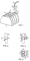
- the contactor 1 has two rows 2, 3 of eight plug connections each, to which two frames 4 are assigned in the exemplary embodiment according to FIG. 1, into which the individual plug connections 5 can be inserted.
- the individual plug connections 5 consist of the insulating sleeve 6, the flat plug connection 7, which is connected to the connecting line 8 generally via a crimp connection.
- the flat connector 7 comes with the knife connector 9 when inserting the single connector 5 into the holding recesses 10 of the frame 4 in an electrically conductive connection.
- When inserting the insulating sleeve 6 press locking projections 11 elastic webs 12 to the side and lock after complete insertion of the individual plug connections 5 behind the lower edge of the frame 4. As shown in FIG.
- the side walls 13 of the holding recess 10 are slightly convex, so that the Latching projections 11 can slide out of the side walls 13 with considerable force when the individual plug connection 5 is pulled out after the webs 12 have given in elastically. This makes it possible to pull out individual plug connections 5.
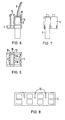
- locking arms 14 are formed on the frame 4 instead of the locking projections, which engage behind the upper edge 15 of the insulating sleeve 6.
- the single plug connection 5 with the insulating sleeve 6 can only be pulled out here after the locking arms 14 have been bent back.
- the elasticity of the side walls 13 is achieved by introducing slot-shaped recesses 16 in the frame, which are only provided on one side in the exemplary embodiment according to FIG.
- the construction according to the invention thus makes it possible to provide the contactor with individual plug connections.
- the individual plug connections are pushed into the frame, which is held over the connections of the device, until they stop in the latch.
- the individual plug connections 5 are held over the latching and pulled off together, so that the assignment to the connection points is retained. If several frames are provided for one device, a corresponding coding can also be provided if the position of the connecting lines 8 permits confusion.
Landscapes
- Details Of Connecting Devices For Male And Female Coupling (AREA)
- Connector Housings Or Holding Contact Members (AREA)
- Manufacturing Of Electrical Connectors (AREA)
Claims (5)
Applications Claiming Priority (2)
| Application Number | Priority Date | Filing Date | Title |
|---|---|---|---|
| DE3516586 | 1985-05-08 | ||
| DE3516586 | 1985-05-08 |
Publications (2)
| Publication Number | Publication Date |
|---|---|
| EP0200993A1 EP0200993A1 (fr) | 1986-11-12 |
| EP0200993B1 true EP0200993B1 (fr) | 1990-03-14 |
Family
ID=6270177
Family Applications (1)
| Application Number | Title | Priority Date | Filing Date |
|---|---|---|---|
| EP86105591A Expired - Lifetime EP0200993B1 (fr) | 1985-05-08 | 1986-04-23 | Dispositif d'enfichage pour la connexion d'appareils électriques, de préférence de disjoncteurs |
Country Status (3)
| Country | Link |
|---|---|
| EP (1) | EP0200993B1 (fr) |
| JP (1) | JP2540458B2 (fr) |
| DE (1) | DE3669622D1 (fr) |
Family Cites Families (4)
| Publication number | Priority date | Publication date | Assignee | Title |
|---|---|---|---|---|
| GB896119A (en) * | 1959-07-21 | 1962-05-09 | Burndy Corp | Locking terminal block |
| US3824553A (en) * | 1973-06-22 | 1974-07-16 | Amp Inc | Low voltage terminal strip capable of withstanding high voltage transients |
| FR2357079A1 (fr) * | 1976-07-02 | 1978-01-27 | Alsthom Cgee | Bloc de jonction a broches de contact |
| EP0105351A1 (fr) * | 1982-04-05 | 1984-04-18 | Akzona Incorporated | Connecteur d'interface |
-
1986
- 1986-04-23 EP EP86105591A patent/EP0200993B1/fr not_active Expired - Lifetime
- 1986-04-23 DE DE8686105591T patent/DE3669622D1/de not_active Expired - Fee Related
- 1986-05-06 JP JP61103734A patent/JP2540458B2/ja not_active Expired - Lifetime
Also Published As
| Publication number | Publication date |
|---|---|
| EP0200993A1 (fr) | 1986-11-12 |
| JP2540458B2 (ja) | 1996-10-02 |
| JPS61256580A (ja) | 1986-11-14 |
| DE3669622D1 (de) | 1990-04-19 |
Similar Documents
| Publication | Publication Date | Title |
|---|---|---|
| EP0709917B1 (fr) | Bloc de connexion avec module électronique | |
| DE2633523C2 (de) | Elektrische Verbindereinheit | |
| DE4003701C2 (de) | Elektr. Anschlußklemme | |
| DE2359425C3 (de) | Kabelklemme und zugehörige Verbindungseinheit | |
| DE2610461C3 (de) | Vorrichtung und Verfahren zur Herstellung eines löt-, schraub- und abisolierfreien Kontaktes an einem feststehenden Anschlunelement, insbesondere für die Fernmeldelinientechnik | |
| DE2045474C3 (de) | Kabelanschlußvorrichtung mit Steckkontakten | |
| EP0706235A2 (fr) | Cosse femelle verrouillable pour une connexion électrique | |
| DE3244470A1 (de) | Elektrisches anschlusssystem und verbindungsglied | |
| EP2147483A2 (fr) | Connecteur électrique comprenant un couvercle antipoussière | |
| EP0440905A2 (fr) | Limiteur de tension | |
| DE3030523A1 (de) | Elektrische anschlussklemme | |
| EP0634813A2 (fr) | Bloc de distribution | |
| DE4014048A1 (de) | Elektrische verbindungsklemme | |
| EP0200993B1 (fr) | Dispositif d'enfichage pour la connexion d'appareils électriques, de préférence de disjoncteurs | |
| DE4327282C2 (de) | Geräteanschlußklemme | |
| DE19532623B4 (de) | Elektrischer Stecker mit einem Betätigungsschieber | |
| DE3932709A1 (de) | Elektrischer steckverbinder | |
| EP0262325A2 (fr) | Dispositif pour distributeur | |
| DE3402870A1 (de) | Schraubenlose klemme | |
| DE2760179C2 (de) | Schraubenlose Anschluß- und/oder Verbindungsklemme | |
| DE102018121792B4 (de) | Elektrische Steckbuchse | |
| DE2621101A1 (de) | Ueberspannungsableitervorrichtung fuer kabelabschlussgeraete der fernmeldelinientechnik | |
| EP0477548A1 (fr) | Dispositif de connexion pour installations à courant faible notamment pour des services de télécommunication et de transmission de données | |
| DE2759848C1 (de) | Schraubenlose Anschlussklemme | |
| DE3617113C2 (fr) |
Legal Events
| Date | Code | Title | Description |
|---|---|---|---|
| PUAI | Public reference made under article 153(3) epc to a published international application that has entered the european phase |
Free format text: ORIGINAL CODE: 0009012 |
|
| AK | Designated contracting states |
Kind code of ref document: A1 Designated state(s): DE FR IT |
|
| 17P | Request for examination filed |
Effective date: 19861218 |
|
| 17Q | First examination report despatched |
Effective date: 19880603 |
|
| GRAA | (expected) grant |
Free format text: ORIGINAL CODE: 0009210 |
|
| AK | Designated contracting states |
Kind code of ref document: B1 Designated state(s): DE FR IT |
|
| REF | Corresponds to: |
Ref document number: 3669622 Country of ref document: DE Date of ref document: 19900419 |
|
| ET | Fr: translation filed | ||
| ITF | It: translation for a ep patent filed |
Owner name: STUDIO JAUMANN |
|
| PLBE | No opposition filed within time limit |
Free format text: ORIGINAL CODE: 0009261 |
|
| STAA | Information on the status of an ep patent application or granted ep patent |
Free format text: STATUS: NO OPPOSITION FILED WITHIN TIME LIMIT |
|
| 26N | No opposition filed | ||
| ITTA | It: last paid annual fee | ||
| PGFP | Annual fee paid to national office [announced via postgrant information from national office to epo] |
Ref country code: FR Payment date: 20000426 Year of fee payment: 15 |
|
| PGFP | Annual fee paid to national office [announced via postgrant information from national office to epo] |
Ref country code: DE Payment date: 20000619 Year of fee payment: 15 |
|
| PG25 | Lapsed in a contracting state [announced via postgrant information from national office to epo] |
Ref country code: FR Free format text: THE PATENT HAS BEEN ANNULLED BY A DECISION OF A NATIONAL AUTHORITY Effective date: 20010430 |
|
| PG25 | Lapsed in a contracting state [announced via postgrant information from national office to epo] |
Ref country code: DE Free format text: LAPSE BECAUSE OF NON-PAYMENT OF DUE FEES Effective date: 20020201 |
|
| REG | Reference to a national code |
Ref country code: FR Ref legal event code: ST |
|
| PG25 | Lapsed in a contracting state [announced via postgrant information from national office to epo] |
Ref country code: IT Free format text: LAPSE BECAUSE OF NON-PAYMENT OF DUE FEES;WARNING: LAPSES OF ITALIAN PATENTS WITH EFFECTIVE DATE BEFORE 2007 MAY HAVE OCCURRED AT ANY TIME BEFORE 2007. THE CORRECT EFFECTIVE DATE MAY BE DIFFERENT FROM THE ONE RECORDED. Effective date: 20050423 |