EP0200993B1 - Steckvorrichtung zum Anschluss elektrischer Geräte, vorzugsweise Schütze - Google Patents
Steckvorrichtung zum Anschluss elektrischer Geräte, vorzugsweise Schütze Download PDFInfo
- Publication number
- EP0200993B1 EP0200993B1 EP86105591A EP86105591A EP0200993B1 EP 0200993 B1 EP0200993 B1 EP 0200993B1 EP 86105591 A EP86105591 A EP 86105591A EP 86105591 A EP86105591 A EP 86105591A EP 0200993 B1 EP0200993 B1 EP 0200993B1
- Authority
- EP
- European Patent Office
- Prior art keywords
- plug connections
- plug
- connections
- individual
- plug device
- Prior art date
- Legal status (The legal status is an assumption and is not a legal conclusion. Google has not performed a legal analysis and makes no representation as to the accuracy of the status listed.)
- Expired - Lifetime
Links
- 230000013011 mating Effects 0.000 description 4
- 238000003780 insertion Methods 0.000 description 2
- 230000037431 insertion Effects 0.000 description 2
- 238000005452 bending Methods 0.000 description 1
- 238000010276 construction Methods 0.000 description 1
- 230000000717 retained effect Effects 0.000 description 1
Images
Classifications
-
- H—ELECTRICITY
- H01—ELECTRIC ELEMENTS
- H01R—ELECTRICALLY-CONDUCTIVE CONNECTIONS; STRUCTURAL ASSOCIATIONS OF A PLURALITY OF MUTUALLY-INSULATED ELECTRICAL CONNECTING ELEMENTS; COUPLING DEVICES; CURRENT COLLECTORS
- H01R13/00—Details of coupling devices of the kinds covered by groups H01R12/70 or H01R24/00 - H01R33/00
- H01R13/46—Bases; Cases
- H01R13/514—Bases; Cases composed as a modular blocks or assembly, i.e. composed of co-operating parts provided with contact members or holding contact members between them
Definitions
- the invention relates to a plug-in device for connection to electrical devices with a number of individual plug connections provided with connecting lines, which can be inserted into mating plug connections and locked in the inserted position.
- the invention has for its object to improve such connection devices in such a way that after insertion of the individual plug connections, the entirety of the inserted connections can be separated from one device. This is achieved in a simple manner in that the individual plug connections can be connected to the mating plug connections by a frame which leaves the mating plug connections of an electrical device, preferably a contactor, and are locked in this frame together with the individual plug connections which can be separated from the device.
- the latching parts are shaped in such a way that the individual plug connections can be pulled out against the latching resistance without tools. It is also possible to equip the connection points of the switching device with live individual plug connections if the individual plug connections are held in an insulating sleeve.
- the plug device according to the invention only requires the plug device to be equipped with individual plug connections at the necessary points.
- the plug-in device according to the invention is particularly well suited for the automatic connection of electrical devices, preferably contactors, since the plug-in can easily be carried out by a robot by specifying the corresponding coordinates.
- the contactor 1 has two rows 2, 3 of eight plug connections each, to which two frames 4 are assigned in the exemplary embodiment according to FIG. 1, into which the individual plug connections 5 can be inserted.
- the individual plug connections 5 consist of the insulating sleeve 6, the flat plug connection 7, which is connected to the connecting line 8 generally via a crimp connection.
- the flat connector 7 comes with the knife connector 9 when inserting the single connector 5 into the holding recesses 10 of the frame 4 in an electrically conductive connection.
- When inserting the insulating sleeve 6 press locking projections 11 elastic webs 12 to the side and lock after complete insertion of the individual plug connections 5 behind the lower edge of the frame 4. As shown in FIG.
- the side walls 13 of the holding recess 10 are slightly convex, so that the Latching projections 11 can slide out of the side walls 13 with considerable force when the individual plug connection 5 is pulled out after the webs 12 have given in elastically. This makes it possible to pull out individual plug connections 5.
- locking arms 14 are formed on the frame 4 instead of the locking projections, which engage behind the upper edge 15 of the insulating sleeve 6.
- the single plug connection 5 with the insulating sleeve 6 can only be pulled out here after the locking arms 14 have been bent back.
- the elasticity of the side walls 13 is achieved by introducing slot-shaped recesses 16 in the frame, which are only provided on one side in the exemplary embodiment according to FIG.
- the construction according to the invention thus makes it possible to provide the contactor with individual plug connections.
- the individual plug connections are pushed into the frame, which is held over the connections of the device, until they stop in the latch.
- the individual plug connections 5 are held over the latching and pulled off together, so that the assignment to the connection points is retained. If several frames are provided for one device, a corresponding coding can also be provided if the position of the connecting lines 8 permits confusion.
Landscapes
- Details Of Connecting Devices For Male And Female Coupling (AREA)
- Connector Housings Or Holding Contact Members (AREA)
- Manufacturing Of Electrical Connectors (AREA)
Description
- Die Erfindung bezieht sich auf eine Steckvorrichtung zum Anschluß an elektrische Geräte mit einer Reihe von mit Anschlußleitungen versehenen Einzelsteckanschlüssen, die in Gegensteckanschlüsse einsteckbar und in der eingesteckten Lage verrast et sind.
- Bei bekannten Anschlußeinrichtungen der obengenannten Art (FR-A-1 262 505, FR-A-2 357 079, WO-A-8 303 717) sind Einzelsteckanschlüsse in Gegensteckanschlüsse einbringbar und durch Rastmittel bzw. Verriegelungen in der eingesteckten Lage arretierbar.
- Der Erfindung liegt die Aufgabe zugrunde, derartige Anschlußeinrichtungen dahingehend zu verbessern, daß nach Einführen der Einzelsteckanschlüsse die Gesamtheit der eingesteckten Anschlüsse gemeinsam von einem Gerät trennbar ist. Dies wird auf einfache Weise dadurch erreicht, daß die Einzelsteckanschlüsse durch ein en die Gegensteckanschlüsse eines elektrischen Gerätes, vorzugsweise eines Schützes, freilassenden Rahmen mit den Gegensteckanschlüssen verbindbar und in diesem gemeinsam mit den Einzelsteckanschlüssen vom Gerät trennbaren Rahmen verrastet sind.
- Um zu erreichen, daß die Einzelsteckanschlüsse gegebenenfalls sowohl einzeln als auch gemeinsam mit der Steckvorrichtung abgezogen werden können ist es vorteilhaft, wenn die Rastteile derart geformt sind, daß ein Ausziehen der Einzelsteckanschlüsse gegen den Rastwiderstand ohne Werkzeug möglich ist. Ein Bestücken der Anschlußstellen des Schaltgerätes auch mit unter Spannung stehenden Einzelsteckanschlüssen ist möglich, wenn die Einzelsteckanschlüsse in einer Isolierhülse gehalten sind. Durch die erfindungsgemäße Steckvorrichtung ist im Gegensatz zum Stand der Technik lediglich eine Bestückung der Steckvorrichtung mit Einzelsteckanschlüssen an den notwendigen Stellen erforderlich. Darüber hinaus eignet sich die erfindungsgemäße Steckvorrichtung besonders gut zum automatischen Anschließen von elektrischen Geräten, vorzugsweise Schützen, da das Einstecken ohne weiteres von einem Roboter bei Angabe der entsprechenden Koordinaten durchführbar ist. Um die Abgangsrichtung der Anschlußleitungen gegebenenfalls besser berücksichtigen zu können ist es vorteilhaft, wenn mehrere Rahmen für ein Gerätvorgesehen sind. Werden Steckvorrichtungen mit erheblichem Klemmdruckverwandt, so daß die Auszugskräfte relativ groß sind, so kann es von Vorteil sein, wenn die Rahmen an der dem Gerät abgewandten Seite von außen zugängliche Rastarme für die Isolierhülsen aufweisen. Bei derartigen Ausführungen ist es trotzdem möglich, einzelne Einzelsteckanschlüsse aus dem Rahmen herauszuziehen, nämlich indem die Rastarme zur Seite gebogen werden.
- Anhand der Zeichnung werden Ausführungsbeispiele gemäß der Erfindung beschrieben.
- Es zeigen:
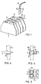
- Fig. 1 eine perspektivische Darstellung eines mit den Anschlußsteckern versehenen Teiles eines Schützes mit aufgesetztem Rahmen und einzuschiebendem Einzeisteckanschluß,
- Fig. 2 eine mögliche Ausbildung des Rahmens in Draufsicht,
- Fig. 3 die der Fig. 2 entsprechende Vorderansicht,
- Fig. 4 die zugehörige Seitenansicht,
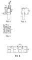
- Fig. 5,6 und 7 Draufsicht, Vorder- und Seitenansicht auf eine weitere Ausführungsform des Rahmens und
- Fig. 8 eine Draufsicht auf eine weitere Ausbildungsmöglichkeit des Rahmens.
- Das Schütz 1 besitzt zwei Reihen 2,3 von jeweils acht Steckanschlüssen, denen im Ausführungsbeispiel nach Fig. 1 zwei Rahmen 4 zugeordnet sind, in die die Einzelsteckanschlüsse 5 einführbar sind. Die Einzelsteckanschlüsse 5 bestehen aus der Isolierhülse 6, dem Flachsteckanschluß 7, der mit der Anschlußleitung 8 im allgemeinen über Quetschverbindung verbunden ist. Der Flachsteckanschluß 7 kommt mit dem Messersteckanschluß 9 beim Einführen des Einzelsteckanschlusses 5 in die Halteausnehmungen 10 des Rahmens 4 in elektrisch leitende Verbindung. Beim Einführen der Isolierhülse 6 drücken Rastvorsprünge 11 elastische Stege 12 zur Seite und verrasten nach vollkommenem Einführen der Einzelsteckanschlüsse 5 hinter der unteren Kante des Rahmens 4. Wie die Fig. 3 zeigt, sind die Seitenwände 13 der Halteausnehmung 10 leicht ballig ausgeführt, so daß die Rastvorsprünge 11 beim Ausziehen des Einzelsteckanschlusses 5 mit erheblicher Kraft nach elastischem Nachgeben der Stege 12 aus den Seitenwänden 13 herausgleiten können. Hierdurch ist das Herausziehen einzelner Einzelsteckanschlüsse 5 möglich. Beim Ausführungsbeispiel nach den Fig. bis 7 sind anstelle der Rastvorsprünge 11 Rastarme 14 am Rahmen 4 angeformt, die hinter die obere Kante 15 der Isolierhülse 6 greifen. Der Einzelsteckanschluß 5 mit der Isolierhülse 6 kann hier lediglich nach Zurückbiegen der Rastarme 14 herausgezogen werden. Die Elastizität der Seitenwände 13 wird durch eingebrachte schlitzförmige Ausnehmungen 16 in dem Rahmen erreicht, die im Ausführungsbeispiel nach Fig. 8 bei einem doppelreihigen Rahmen nur einseitig vorgesehen sind. Durch den erfindungsgemäßen Aufbau ist es somit möglich, das Schütz mit Einzelsteckanschlüssen zu versehen. Die Einzelsteckanschlüsse werden in die Rahmen, die über die Anschlüsse des Gerätes gehalten werden, bis zum Anschlag in der Verrastung eingeschoben. Beim gemeinsamen Abziehen der gesteckten Leitungen werden die Einzelsteckanschlüsse 5 über die Verrastung gehalten und gemeinsam abgezogen, so daß die Zuordnung zu den Anschlußstellen erhalten bleibt. Beim Vorsehen mehrerer Rahmen bei einem Gerät kann auch eine entsprechende Codierung vorgesehen werden, falls die Lage der Anschlußleitungen 8 ein Verwechseln zuläßt.
Claims (5)
Applications Claiming Priority (2)
| Application Number | Priority Date | Filing Date | Title |
|---|---|---|---|
| DE3516586 | 1985-05-08 | ||
| DE3516586 | 1985-05-08 |
Publications (2)
| Publication Number | Publication Date |
|---|---|
| EP0200993A1 EP0200993A1 (de) | 1986-11-12 |
| EP0200993B1 true EP0200993B1 (de) | 1990-03-14 |
Family
ID=6270177
Family Applications (1)
| Application Number | Title | Priority Date | Filing Date |
|---|---|---|---|
| EP86105591A Expired - Lifetime EP0200993B1 (de) | 1985-05-08 | 1986-04-23 | Steckvorrichtung zum Anschluss elektrischer Geräte, vorzugsweise Schütze |
Country Status (3)
| Country | Link |
|---|---|
| EP (1) | EP0200993B1 (de) |
| JP (1) | JP2540458B2 (de) |
| DE (1) | DE3669622D1 (de) |
Family Cites Families (4)
| Publication number | Priority date | Publication date | Assignee | Title |
|---|---|---|---|---|
| GB896119A (en) * | 1959-07-21 | 1962-05-09 | Burndy Corp | Locking terminal block |
| US3824553A (en) * | 1973-06-22 | 1974-07-16 | Amp Inc | Low voltage terminal strip capable of withstanding high voltage transients |
| FR2357079A1 (fr) * | 1976-07-02 | 1978-01-27 | Alsthom Cgee | Bloc de jonction a broches de contact |
| EP0105351A1 (de) * | 1982-04-05 | 1984-04-18 | Akzona Incorporated | Zwischensteckvorrichtung |
-
1986
- 1986-04-23 EP EP86105591A patent/EP0200993B1/de not_active Expired - Lifetime
- 1986-04-23 DE DE8686105591T patent/DE3669622D1/de not_active Expired - Lifetime
- 1986-05-06 JP JP61103734A patent/JP2540458B2/ja not_active Expired - Lifetime
Also Published As
| Publication number | Publication date |
|---|---|
| DE3669622D1 (de) | 1990-04-19 |
| JP2540458B2 (ja) | 1996-10-02 |
| JPS61256580A (ja) | 1986-11-14 |
| EP0200993A1 (de) | 1986-11-12 |
Similar Documents
| Publication | Publication Date | Title |
|---|---|---|
| EP0709917B1 (de) | Anschlussklemmenblock mit Elektronikmodul | |
| DE2633523C2 (de) | Elektrische Verbindereinheit | |
| DE4003701C2 (de) | Elektr. Anschlußklemme | |
| DE2045474C3 (de) | Kabelanschlußvorrichtung mit Steckkontakten | |
| DE2359425C3 (de) | Kabelklemme und zugehörige Verbindungseinheit | |
| DE2610461C3 (de) | Vorrichtung und Verfahren zur Herstellung eines löt-, schraub- und abisolierfreien Kontaktes an einem feststehenden Anschlunelement, insbesondere für die Fernmeldelinientechnik | |
| EP0706235A2 (de) | Verriegelbare Flachsteckhülse für eine elektrische Verbindung | |
| DE3244470A1 (de) | Elektrisches anschlusssystem und verbindungsglied | |
| EP0440905A2 (de) | Spannungsbegrenzer | |
| DE4014048A1 (de) | Elektrische verbindungsklemme | |
| DE3030523A1 (de) | Elektrische anschlussklemme | |
| EP0200993B1 (de) | Steckvorrichtung zum Anschluss elektrischer Geräte, vorzugsweise Schütze | |
| DE4327282C2 (de) | Geräteanschlußklemme | |
| DE3850198T2 (de) | Trennbare Verbindungsvorrichtung zwischen einem leitenden Stift und mindestens einem Verbindungsdraht. | |
| DE102018121792B4 (de) | Elektrische Steckbuchse | |
| DE19532623B4 (de) | Elektrischer Stecker mit einem Betätigungsschieber | |
| DE3932709A1 (de) | Elektrischer steckverbinder | |
| EP0262325A2 (de) | Anordnung für Hauptverteiler | |
| DE2760179C2 (de) | Schraubenlose Anschluß- und/oder Verbindungsklemme | |
| DE2621101A1 (de) | Ueberspannungsableitervorrichtung fuer kabelabschlussgeraete der fernmeldelinientechnik | |
| EP0477548A1 (de) | Steckverbindungseinrichtung für Schwachstromanlagen insbesondere der Tele- und Datenkommunikation | |
| DE2759848C1 (de) | Schraubenlose Anschlussklemme | |
| DE8513625U1 (de) | Steckvorrichtung zum Anschluß elektrischer Geräte, vorzugsweise Schütze | |
| DE3617113C2 (de) | ||
| DE69221606T2 (de) | Integrierter Anschlussblock zusammenhängend mit Stecker |
Legal Events
| Date | Code | Title | Description |
|---|---|---|---|
| PUAI | Public reference made under article 153(3) epc to a published international application that has entered the european phase |
Free format text: ORIGINAL CODE: 0009012 |
|
| AK | Designated contracting states |
Kind code of ref document: A1 Designated state(s): DE FR IT |
|
| 17P | Request for examination filed |
Effective date: 19861218 |
|
| 17Q | First examination report despatched |
Effective date: 19880603 |
|
| GRAA | (expected) grant |
Free format text: ORIGINAL CODE: 0009210 |
|
| AK | Designated contracting states |
Kind code of ref document: B1 Designated state(s): DE FR IT |
|
| REF | Corresponds to: |
Ref document number: 3669622 Country of ref document: DE Date of ref document: 19900419 |
|
| ET | Fr: translation filed | ||
| ITF | It: translation for a ep patent filed | ||
| PLBE | No opposition filed within time limit |
Free format text: ORIGINAL CODE: 0009261 |
|
| STAA | Information on the status of an ep patent application or granted ep patent |
Free format text: STATUS: NO OPPOSITION FILED WITHIN TIME LIMIT |
|
| 26N | No opposition filed | ||
| ITTA | It: last paid annual fee | ||
| PGFP | Annual fee paid to national office [announced via postgrant information from national office to epo] |
Ref country code: FR Payment date: 20000426 Year of fee payment: 15 |
|
| PGFP | Annual fee paid to national office [announced via postgrant information from national office to epo] |
Ref country code: DE Payment date: 20000619 Year of fee payment: 15 |
|
| PG25 | Lapsed in a contracting state [announced via postgrant information from national office to epo] |
Ref country code: FR Free format text: THE PATENT HAS BEEN ANNULLED BY A DECISION OF A NATIONAL AUTHORITY Effective date: 20010430 |
|
| PG25 | Lapsed in a contracting state [announced via postgrant information from national office to epo] |
Ref country code: DE Free format text: LAPSE BECAUSE OF NON-PAYMENT OF DUE FEES Effective date: 20020201 |
|
| REG | Reference to a national code |
Ref country code: FR Ref legal event code: ST |
|
| PG25 | Lapsed in a contracting state [announced via postgrant information from national office to epo] |
Ref country code: IT Free format text: LAPSE BECAUSE OF NON-PAYMENT OF DUE FEES;WARNING: LAPSES OF ITALIAN PATENTS WITH EFFECTIVE DATE BEFORE 2007 MAY HAVE OCCURRED AT ANY TIME BEFORE 2007. THE CORRECT EFFECTIVE DATE MAY BE DIFFERENT FROM THE ONE RECORDED. Effective date: 20050423 |