EP0200651B1 - Dreielektrodenionenquelle mit einer einzigen Hochfrequenzionisationskammer und mit multipolarer magnetischer Umschliessung - Google Patents
Dreielektrodenionenquelle mit einer einzigen Hochfrequenzionisationskammer und mit multipolarer magnetischer Umschliessung Download PDFInfo
- Publication number
- EP0200651B1 EP0200651B1 EP86400931A EP86400931A EP0200651B1 EP 0200651 B1 EP0200651 B1 EP 0200651B1 EP 86400931 A EP86400931 A EP 86400931A EP 86400931 A EP86400931 A EP 86400931A EP 0200651 B1 EP0200651 B1 EP 0200651B1
- Authority
- EP
- European Patent Office
- Prior art keywords
- ionization
- electrode
- chamber
- ions
- source according
- Prior art date
- Legal status (The legal status is an assumption and is not a legal conclusion. Google has not performed a legal analysis and makes no representation as to the accuracy of the status listed.)
- Expired - Lifetime
Links
Images

Classifications
-
- H—ELECTRICITY
- H01—ELECTRIC ELEMENTS
- H01J—ELECTRIC DISCHARGE TUBES OR DISCHARGE LAMPS
- H01J37/00—Discharge tubes with provision for introducing objects or material to be exposed to the discharge, e.g. for the purpose of examination or processing thereof
- H01J37/02—Details
- H01J37/04—Arrangements of electrodes and associated parts for generating or controlling the discharge, e.g. electron-optical arrangement, ion-optical arrangement
- H01J37/08—Ion sources; Ion guns
-
- H—ELECTRICITY
- H01—ELECTRIC ELEMENTS
- H01J—ELECTRIC DISCHARGE TUBES OR DISCHARGE LAMPS
- H01J27/00—Ion beam tubes
- H01J27/02—Ion sources; Ion guns
- H01J27/16—Ion sources; Ion guns using high-frequency excitation, e.g. microwave excitation
Definitions
- the present invention relates to ion sources with a single ionization chamber in which the plasma is created by excitation of a gas using a high frequency electric field, for the formation of either plasmas or of ion beams.
- Such ion sources are proving to be more and more in demand, on the one hand, for mechanical surface treatments of materials, with a view to imparting them increased resistance to corrosion and wear, and, d on the other hand, for their application in the manufacturing phases of integrated circuits with a high level of integration, for example for cleaning substrates, depositing thin layers (by epitaxy or for producing passivation layers), stripping of resins and engraving patterns.
- the invention aims to produce an ion source making it possible to obtain beams with a large section, uniform over almost their entire section and stable over time, from chemically reactive gases, either on the materials of the landfill, either between them.
- Ion sources at an ionization chamber are known in the art.
- ion sources are known to an ionization chamber whose plasma is created by high frequency excitation using an alternating electric field applied between two electrodes facing each other and having shapes various (planar, cylindrical or spherical), depending on the high frequency diode type with capacitive coupling.
- This structure is widely used currently in plasma technology due to its simplicity and the fact that it is well suited for the ionization of reactive gases, without any problem of lifetime, but on the other hand it has shortcomings with regard to the uniformity of plasma, pollution of a target, carried by the anode, following the sputtering of the cathode under the impact of ions, the degree of plasma ionization, the operating pressure limit, because the efficiency d ionization is very weak, and the control of the energy of the ions arriving on one or the other of the electrodes, both participating in the creation of the plasma and consequently having no degree of freedom as for their polarization.
- Ion sources are also known to an ionization chamber whose plasma is created by the application of a static continuous electric field between a hot electron-emitting filament and an anode constituting the walls of the chamber. , at the periphery of which a magnetic confinement of the multi-mirror type is produced by alternating magnetic poles which give a structure of a multipolar direct current diode.
- Ion sources with a single ionization chamber are also known in which the multi-mirror magnetic confinement is associated with the ionization or excitation of neutrals by an alternating electric field either of high frequency or of very high frequency so to combine the advantages and reduce the disadvantages which may result from the structures mentioned above under A and B.
- US Patent No. 4,481,062 describes an ion source with a multipolar magnetic confinement chamber with a hot cathode, heated by direct current or alternating current from the sector, and an anode, a direct current source applying a difference. of continuous potential between cathode and anode.
- ion sources with two or three ionization chambers have also been proposed, for example in French patent application No. 2,550,681 filed on August 12, 1983 by the applicant. Deur and made available to the public from February 15, 1985, the confinement of ions and electrons in the third ionization chamber (when there are three chambers) being obtained by a multi-mirror magnetic configuration produced by crowns or rows of alternating magnetic poles arranged around this chamber.
- This type of source is very suitable for operation with chemically reactive gases which do not give rise to insulating deposits because in this event the excitation, by continuous electric field of the plasma of the third chamber has the same drawback as that described in About sources of type A.
- the three-chamber source thus obtained is governed by a large number of parameters and that in return for its good performance (uniformity, stability of the plasma and ionization efficiency), it is more difficult to control and therefore to automate.
- the device comprises a plane structure of the diode type without any magnetic field, the two electrodes forming a diode facing each other.
- the ion source according to DE-A-3.134.337 is characterized by a planar structure of the diode type, with two ionization electrodes which face each other, the two electrodes being plane and parallel, and the absence of magnetic field.
- a spatial structure of the triode type is provided, with two ionization electrodes in contact with the plasma, which do not face each other, and an independent polarization electrode.
- the object of the present invention is to improve the sources of ions of the previous type, in particular the sources of ions of type C above, in order to obtain sources having a very long lifespan - the lifespan being a fundamental parameter for industrial application - while ensuring the best compromise between, on the one hand, the criteria characterizing the available ion flow, namely in particular uniformity and stability over large sections, the absence of pollution by particles or parasitic radiation, the ratio of the flow of ions to the flow of neutrals, and, on the other hand, the criteria characterizing the source of ions, in particular its simplicity of implementation and automation, and its reliability, criteria which, according to the specifications of current applications, must be used (maximized or minimized as the case may be).
- the ion source according to the invention achieves a significant improvement in terms of simplicity of implementation and automation at the expense of a sacrifice. as for the ratio, ion flux / neutral flux reflecting the ionization efficiency of the source as a result of an increase in the limit pressure up to which the discharge can be maintained in the source with a charge density significant.
- the new ion source is an ion source with a single ionization chamber in which the plasma is created by the excitation of a gas using a high frequency electric field between two ionization electrodes and it implements a third polarization electrode, with independent polarization, and magnetic confinement of the multipolar type, that is to say multimirror, produced by crowns or bands of alternating magnetic poles arranged around from this room.
- the ion source according to the invention can operate according to two modes, the first, called “plasma ion source” leading to irradiation of the samples within the plasma itself and the second called “beam ion source” leading to irradiation of the samples outside the ionization chamber, in a gaseous atmosphere at independently controllable pressure.
- the sample to be irradiated by the ions is placed inside the ionization chamber against the third electrode which is then a full target (with the possible gas evacuation orifice nearby) and the ions are accelerated from the plasma where they are created by the negative voltage applied to the third electrode, which ensures independence between the intensity of the ion flow and the energy of the ions; on the other hand the incidence of the ions on the sample is practically normal (perpendicular) and the irradiation is done at the pressure necessary for the establishment of the plasma and in an atmosphere of neutral particles (molecules or radicals) resulting from the creation of this plasma whose physicochemistry is most often very complex.
- the exterior of the ionization chamber is generally placed at atmospheric pressure and it will therefore be necessary to provide, between the various electrodes, elements ensuring both electrical insulation and sealing preventing the passage of gases. It is however possible to place the entire ionization chamber in an enclosure where a partial vacuum prevails.
- the two ionization electrodes are connected to the terminals of the high frequency generator by performing a capacitive coupling which creates the plasma, unlike what happens in ion sources in which the difference in high frequency potential is applied to the terminals of an electrode in the form of an induction coil, the coupling then being of the inductive type (certain ion sources of type C above).
- the internal ionization electrode can be either of the multitube type, the tubes having for example a circular or rectangular section, possibly square with in some cases injection of gas to be ionized by the tubes, or constituted by a surface of planar or curved shape. (especially cylindrical or spherical).
- the current density of the ion flow is lower than for a multitube interior ionization electrode but the self-polarization voltage of this plane or curve electrode is more high; therefore, such a shape is very favorable for the deposition, on the polarization electrode, of a thin layer of particles extracted from the internal ionization electrode under the impact of high energy ions from the plasma, according to the known method.
- the fact of giving the internal ionization electrode a concave shape (cylindrical or spherical) in the direction of the polarization electrode makes it possible to concentrate the flux of neutrals on a smaller surface of the polarization electrode and therefore to increase the growth rate of the layer on this restricted surface.
- any deposit resulting from the spraying the interior ionization electrode constitutes "pollution"; for these methods, a multitube interior ionization electrode is therefore clearly preferable. For many applications, this structure will actually be the most suitable.
- a plasma contains electrons and ions, but also neutrals, free radicals and photons, which can be active either in the sense of the deposition or in the sense of the etching, it is necessary to provide for the evacuation of the gases injected and of those formed within the plasma either in volume or as a result of interaction with the sample (loading effect). You must be able to independently regulate the flow and pressure of the neutrals present in the chamber.
- the orifice for communication with the pumping system can be formed either in the anode or in the polarization electrode; an adjustment valve is advantageously provided on the pumping pipe.
- the multi-mirror magnetic confinement is ensured from permanent magnets of as good quality as possible (for example cobalt-samarium magnets), of either cylindrical or parallelepipedal shapes arranged in contact with the walls of the chamber which are non-magnetic and d thickness as small as possible so as not to weaken the magnetic field of these magnets.
- permanent magnets for example cobalt-samarium magnets
- cobalt-samarium magnets of either cylindrical or parallelepipedal shapes arranged in contact with the walls of the chamber which are non-magnetic and d thickness as small as possible so as not to weaken the magnetic field of these magnets.
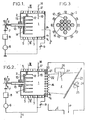
- FIGS. 1 to 3 illustrate two embodiments with a multitube interior ionization electrode.
- FIGS. 1 and 2 illustrate, in axial section, two ion sources of the triode type according to the invention comprising a single ionization chamber, with high frequency excitation and with multipolar magnetic configuration
- FIG. 3 which is a section through III -III of Figures 1 and 2 precisely showing the structure providing multipolar magnetic confinement.
- FIG. 1 is specially designed to operate according to the operating mode of a plasma ion source
- FIG. 2 is specially designed to operate according to the operating mode of a beam ion source , as previously indicated.
- the ion source firstly comprises a single ionization chamber 1 which is, on the one hand, evacuated and, on the other hand, supplied with gas to be transformed into plasma, as indicated below. .
- an interior ionization electrode 2 which, in the embodiments of FIGS. 1 and 2, is constituted by a multitube interior ionization electrode; this internal ionization electrode is advantageously cooled by circulation of a fluid arriving at a and leaving at b.
- the interior ionization electrode 2 cooperates with an exterior ionization electrode 3 which constitutes a large part of the wall of the chamber 1.
- a third electrode is provided, consisting of a full polarization electrode 4 1 (apart from possibly one or more orifices 4b for evacuating chamber 1), as is the case in the source of FIG. 1, or by an ion emission grid 4 2 capable of letting the plasma ions pass from inside the ionization chamber, as in the embodiment of FIG. 2, the third electrode, of polarization, 4 1 or 4 2 being disposed at the other end of the ionization chamber 1 relative to the neighboring end of the interior ionization electrode 2.
- a sealing and electrical isolation ring 4a is disposed along the periphery of the electrode 4 1 , 4 2 on the side of the ionization chamber 1 which allows the entire chamber 1 to be evacuated if desired.
- the magnetic confinement is carried out by means of a system of magnetic poles NORD (N) and SUD (S) referenced 5, which are arranged in an alternating manner, in particular as seen in FIG. 3.
- the two ionization electrodes (interior 2 and exterior 3) are subjected to a high frequency alternating high voltage which produces, by capacitive coupling inside the chamber 1, a plasma from the gas introduced into this chamber.
- the high frequency is produced by a high frequency generator 6 the frequency of which is at least equal to the value of the lower limit frequency from which the plasma in the chamber is permanently ignited in a state of equilibrium independent of time, this high frequency of the generator 6 being for example greater than 20-50 kHz.
- a blocking capacitor 7 which eliminates any DC component in the supply of the internal ionization electrode 2, therefore any direct current transport between this ionization electrode.
- inner 2 and the outer ionization electrode 3 and which thus ensures said inner ionization electrode 2 automatic continuous polarization with respect to the electrode 3, thus creating an electrical asymmetry between these two electrodes, in addition to geometric asymmetry.
- impedance matching circuit 8 in the supply of the interior ionization electrode 2 an impedance matching circuit 8 so as to improve the transfer of power from the generator 6 to the electrical discharge in the chamber 1, by reducing the power reflected by the impedance thus adapted.
- a variable but continuous voltage source 9, so as to apply to the full polarization electrode 4, or to the ion emission grid 4 2 a potential chosen a priori with respect to the external ionization electrode 3, this potential generally being of negative value for achieving the acceleration of the ions.
- the polarization electrode 4 1 is a solid target, apart from one or more evacuation orifices 4b which communicate with a pumping device, preferably adjustable, symbolically represented by the arrow P.
- the polarization electrode 4 can carry plates constituting the samples struck by the ions and also the neutral ones (resulting for example from the spraying of the interior ionization electrode 2 in the case of a deposit on this electrode. internal ionization) of the plasma formed in the chamber 1 by the discharge caused between the internal ionization electrode 2 and the external ionization electrode 3 under the effect of the high frequency generator 6. As indicated previously, this plasma is produced from the gas or gases arriving in 10 and / or in 18.
- the ion source of FIG. 2 there are provided, behind the ion emission grid 4 2 with the openings 4b, two additional electrodes forming an extraction assembly, namely an accelerating electrode 20 and a decelerating electrode 21 brought, with respect to the electrode 4 2 , to negative potential differences, the electrode 20 being more negative than the electrode 21 (the voltage sources supplying have not been illustrated in FIG. 2 the electrodes 20 and 21 because they are conventional; on the other hand, these voltage sources are illustrated in the embodiment of FIG. 5).
- the additional electrodes 20 and 21 are perforated with the ion beam leaving the source through, through the openings of the decelerating electrode 21, as illustrated by the arrows 22 and it arrives (at f) in an enclosure E evacuated by a system pumping materialized by the arrow P.
- This chamber E constitutes the reaction chamber in which the sample is placed.
- the sample is carried by a sample holder or wafer holder 23 which can rotate, as indicated by the arrow 24, around an axis 25; it is located in the independent pumping chamber E in which the pressure Pe can be brought to be lower than Ps which is the pressure in the ionization chamber 1.
- plasma and “beam”, it is possible, for example, to etch, in particular an integrated circuit, plasma etching in the case of FIG. 1 (operation of the RIE type: Reactive Ion Etching) and reactive beam etching in the case of Figure 2 (RIBE type operation: Reactive lon Beam Etching).
- the etching takes place within the ionization chamber 1 by means of the plasma formed in this chamber and it is very uniform thanks to the excellent homogeneity of the plasma obtained in the ion source according to the invention; it is done by impact under normal incidence (perpendicular to the sample) and can therefore be very anisotropic, which, as a general rule, is the aim sought.
- the ion extraction optic constituted by the electrodes 20 and 21, makes it possible to extract a beam of ions f from the ionization chamber, to propagate it in a rarefied atmosphere (Pe much smaller than Ps), these ions being projected onto the sample placed on the wafer holder 23, the flux and energy of the ions being sufficient to ensure excellent etching, with the advantage here of being able to modify the angle of incidence of ions on the sample.
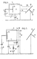
- FIG. 4 illustrates a variant of the embodiment of FIG. 1, in which the multibube electrode 2 of FIG. 1 has been replaced by a planar electrode 2a.
- Figure 4 is a schematic figure on which we find the multipole assemblies 5, the generator-generator 6 which generates the high frequency applied, between the two ionization electrodes, namely the plane interior ionization electrode 2a and the external ionization electrode 3, carrying out the capacitive coupling, in the ionization chamber 1, and the capacitor 7 on the other hand, the optional circuit 8 of impedance adaptation of FIG. 1 has not been illustrated.
- the third polarization electrode is an ion emission grid 4c letting the ion beam 22a pass through its very fine meshes 4e.
- FIG. 4 shows neither the evacuated enclosure, nor the pumping source, which can be analogous to that of the ion source illustrated in FIG. 2.
- the ion emission grid 4c as the sample holder 23 are set to the ground potential, the assembly of the two ionization electrodes 3 and 2a being brought to a positive potential with respect to the ground by the source 9a which can apply a variable potential of, for example, between 50 and 15 volts relative to the ground; in this case the ions have a low energy arriving on the sample, energy of the order of 50 to 150 eV.
- FIG. 4 illustrates, opposite a plane interior ionization electrode 2a, a single-grid optic, namely the ion emission grid 4c in FIG. 5 which is a variant of FIG. 2, illustrates an optic with several grids, namely three grids always with a plane interior ionization electrode 2a.
- FIG. 5 is a simplified figure on which the system of magnetic poles 5 has not been explained, this system surrounding the anode 3.
- the evacuated enclosure E of FIG. 2 has not been illustrated in which the rotary sample holder 23 is carried carried by an axis 25.
- isolation capacitors 7 and 7a that the connection of the generator 6 to the ground is possible, in the case of FIG. 5, the coupling with the chamber being made through these isolation capacitors 7, 7a.
- two sources 9b and 9c are provided in the embodiment of FIG. 5, between which is arranged a choke coil 28 intended to block the high frequency.
- the polarization of the third electrode serves to attract the ions formed in this plasma and to communicate to them the desired energy for the interaction with the sample, carried by the sample holder 23 or by the third electrode, their flux (1 ′, K ) over the whole of the full polarization electrode or ion emission grid being practically not modified by the value of the voltage applied to this third electrode; this is the advantage of the "triode" structure which makes it possible to independently fix both the flux and the energy of the ions which act on a sample carried by this third electrode, in the case of the invention.
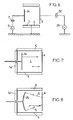
- polarization by direct voltage can be provided, but also, as a variant, polarization by an auxiliary AC voltage, the frequency of which may be low (a few kHz), the plasma being created moreover for the cases where the sample is a dielectric or if the layer produced is itself of a dielectric nature. Indeed a continuous polarization is then ineffective; therefore the variant with negative bias voltage of the third electrode relative to the ionization electrodes is of more general use, to be produced according to the assembly illustrated schematically in FIG. 6.
- FIG. 6 instead of a continuous polarization of the third electrode, provision is made for polarization by an auxiliary AC voltage of frequency equal to a few kHz).
- a planar internal ionization electrode 2a is used, an external ionization electrode 3, a third electrode designated 4 which may be of the type of ion emission grid or full sample holder target.
- a pole system 5 a high frequency generator 6 and a capacitor 7.
- the low frequency alternating generator at a frequency of a few kHz (for example 1 to 10 kHz), is illustrated at 29.
- a capacitor 30 is placed in series with generator 29 between the ground and electrode 4.
- FIG. 6 is more general with regard to the application, since it is also suitable for dielectric samples or the elaborate layers of dielectric nature.
- an alternating generator such as 29, with a blocking capacitor 30, is also applicable as a variant of FIG. 2, that is to say when an accelerating electrode 20 is provided and a decelerating electrode 21, the energy being communicated to the ions by the latter electrodes; the generator 29-capacitor 30 assembly is in this case connected to the ion emission grid 4 2 in place of the continuous generator 9.
- the electrode 4 2 could be either connected to the external ionization electrode 3, or left floating, that is to say connected to the external ionization electrode by a high value resistor.
- FIG. 7 illustrates another variant with a planar internal ionization electrode 2a in which, in addition to the magnet system 5, a second magnet system 5a is also provided arranged against the end of the most ionization chamber 1 next to the internal ionization electrode 2a, therefore on the side opposite the end closed by the third electrode 4 (of the type 4 1 or 4 2 ),
- FIGS. 1 to 3 multi-tube (FIGS. 1 to 3) or planar internal ionization electrodes (FIGS. 4 to 7).
- FIG. 8 it is also possible to use a curved interior ionization electrode, as illustrated in FIG. 8, on which the interior ionization electrode is referenced 2b.
- FIG. 8 we find the other elements of FIG. 7.
- a curved electrode of the spherical or cylindrical type is that it more or less focuses the neutrals, sprayed from this internal ionization electrode, in the direction of the third electrode 4, as illustrated by the arrows f 1 limiting the ion beam produced by the interior ionization electrode 2b, the concavity of which is directed towards the third electrode 4.
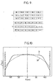
- FIG. 9 illustrates two embodiments a and b of multiple linear mirrors produced by strips or rows of poles NORD (N) and SOUTH (S), the strips of poles being able to be either broken (embodiment a of FIG. 9 ) or continuous (embodiment b of FIG. 9).
- NORD N
- SOUTH S
- FIG. 10 illustrates the advantage of multipolar magnetic confinement which is one of the characteristics of the invention.
- the curve 31 in solid lines corresponds to the case of a multipolar magnetic confinement according to the invention, while the curve 32 in broken lines illustrates the variation of the profile of the current density for the same ion source but in which there is removed magnetic confinement.
- FIG. 11 is illustrated by curve 33 in solid lines the characteristics of an ion source according to the invention and by a curve 34 in dashed lines that of a source of analogous ions, but in which there n there is no confinement around the ionization chamber, the alternating magnetic pole lines being eliminated.
- FIG. 11 to which the discharge pressures on the abscissa and the current densities j + (in mA / cm 2 ) of the ion flux I ', IK (in mA) irradiating the polarization electrode, have been plotted solid target, on the ordinate, shows that the ion current densities of a source according to the invention, although less than the values obtained for a continuous excitation in a tetrode or a pentode (according to French patent application no.
- 2,550,681 cited above of the applicant are compatible for example with the criteria required for reactive ion etching both in plasma of the RIE type and in beam of the RIBE type; in fact in both cases it requires current densities of between 0.5 and 1 mA / cm 2; value that can be achieved and even exceeded by the ion source according to the invention for discharge pressures between 10- 2 and 10- 1 pascal pascal and adequate high frequency power between 500 and 1000 watts.
- FIG. 12 illustrates the variation in the current density of the ion flow (in mA / cm 2 ), plotted on the ordinate, as a function of the pressure of CF 4 (carbon tetrafluoride) introduced into the ionization chamber in the discharge, plotted on the abscissa, for a source according to the invention, one with an internal ionization electrode with several tubes (curve 35 in solid lines) and the other similar but comprising a plane internal ionization electrode (curve 36 in phantom).
- CF 4 carbon tetrafluoride
- the invention makes it possible to produce an ion source capable of being used both in plasma and in beam and giving full satisfaction with regard to the lifetime which is very long, the homogeneity of the plasma which is very good, fragmentation of the injected gas is medium, the ionization efficiency is average and the limit pressure which is of the order of 10 -2 pascal, and this by means of a relatively simple structure, an easy feeding electrodes and automation simplified by the low number of independent parameters.
- the ion source according to the invention is particularly suitable for carrying out etching, in particular integrated circuits, using carbon tetrafluoride and optionally other reactive gases of fluorocarbon or chlorocarbon type, optionally mixed with oxygen.
- Such an ion source is in fact applicable for the following techniques using chemically reactive ion fluxes (formed from oxygenated, nitrogenous, fluorinated or chlorinated compounds for example): technology of integrated circuits with high integration for processes such oxidation of semiconductors, etching of integrated circuits by a beam of reactive ions, nitriding of semiconductors, deposition of thin layers by epitaxy, stripping of masks in resin and treatment of various materials (tools in particular).
- chemically reactive ion fluxes formed from oxygenated, nitrogenous, fluorinated or chlorinated compounds for example
Claims (15)
Applications Claiming Priority (2)
| Application Number | Priority Date | Filing Date | Title |
|---|---|---|---|
| FR8506492A FR2581244B1 (fr) | 1985-04-29 | 1985-04-29 | Source d'ions du type triode a une seule chambre d'ionisation a excitation haute frequence et a confinement magnetique du type multipolaire |
| FR8506492 | 1985-04-29 |
Publications (2)
| Publication Number | Publication Date |
|---|---|
| EP0200651A1 EP0200651A1 (de) | 1986-11-05 |
| EP0200651B1 true EP0200651B1 (de) | 1990-05-30 |
Family
ID=9318780
Family Applications (1)
| Application Number | Title | Priority Date | Filing Date |
|---|---|---|---|
| EP86400931A Expired - Lifetime EP0200651B1 (de) | 1985-04-29 | 1986-04-28 | Dreielektrodenionenquelle mit einer einzigen Hochfrequenzionisationskammer und mit multipolarer magnetischer Umschliessung |
Country Status (4)
| Country | Link |
|---|---|
| US (1) | US4873445A (de) |
| EP (1) | EP0200651B1 (de) |
| DE (1) | DE3671679D1 (de) |
| FR (1) | FR2581244B1 (de) |
Families Citing this family (33)
| Publication number | Priority date | Publication date | Assignee | Title |
|---|---|---|---|---|
| US5089746A (en) * | 1989-02-14 | 1992-02-18 | Varian Associates, Inc. | Production of ion beams by chemically enhanced sputtering of solids |
| GB8905073D0 (en) * | 1989-03-06 | 1989-04-19 | Nordiko Ltd | Ion gun |
| SE9403988L (sv) * | 1994-11-18 | 1996-04-01 | Ladislav Bardos | Apparat för alstring av linjär ljusbågsurladdning för plasmabearbetning |
| JP3123735B2 (ja) * | 1995-04-28 | 2001-01-15 | 株式会社日立製作所 | イオンビーム処理装置 |
| US6184532B1 (en) | 1997-12-01 | 2001-02-06 | Ebara Corporation | Ion source |
| US6271529B1 (en) * | 1997-12-01 | 2001-08-07 | Ebara Corporation | Ion implantation with charge neutralization |
| US6515426B1 (en) * | 1998-12-15 | 2003-02-04 | Hitachi, Ltd. | Ion beam processing apparatus and method of operating ion source therefor |
| US6646223B2 (en) * | 1999-12-28 | 2003-11-11 | Texas Instruments Incorporated | Method for improving ash rate uniformity in photoresist ashing process equipment |
| JP2001279455A (ja) * | 2000-03-29 | 2001-10-10 | Canon Inc | 堆積膜形成方法及び堆積膜形成装置 |
| KR100382720B1 (ko) * | 2000-08-30 | 2003-05-09 | 삼성전자주식회사 | 반도체 식각 장치 및 이를 이용한 반도체 소자의 식각 방법 |
| US20050026436A1 (en) * | 2000-12-21 | 2005-02-03 | Hogan Timothy J. | Method for improving ash rate uniformity in photoresist ashing process equipment |
| DE10248055B4 (de) * | 2002-10-11 | 2012-02-23 | Spectro Analytical Instruments Gmbh & Co. Kg | Methode zur Anregung optischer Atom-Emission und apparative Vorrichtung für die spektrochemische Analyse |
| EP1774562B1 (de) * | 2004-06-08 | 2012-02-22 | Dichroic cell s.r.l. | System zur plasmaunterstützten chemischen aufdampfung bei niedrigen energien |
| DE102005054605B4 (de) * | 2005-11-16 | 2010-09-30 | Bruker Daltonik Gmbh | Automatische Reinigung von Ionenquellen |
| GB0604655D0 (en) * | 2006-03-08 | 2006-04-19 | Smith Alan A | Plasma confinement |
| DE102009017647A1 (de) * | 2009-04-16 | 2010-10-21 | Siemens Aktiengesellschaft | Ionenquelle zum Erzeugen eines Partikelstrahls, Elektrode für eine Ionenquelle sowie Verfahren zum Einleiten eines zu ionisierenden Gases in eine Ionenquelle |
| JP5872541B2 (ja) * | 2010-04-09 | 2016-03-01 | イー エイ フィシオネ インストルメンツ インコーポレーテッドE.A.Fischione Instruments, Inc. | 改良型イオン源 |
| US8633452B2 (en) | 2011-07-13 | 2014-01-21 | Fei Company | Methods and structures for rapid switching between different process gases in an inductively-coupled plasma (ICP) ion source |
| US8779351B2 (en) * | 2012-12-19 | 2014-07-15 | Schlumberger Technology Corporation | Ion source employing secondary electron generation |
| US8822912B2 (en) | 2012-12-19 | 2014-09-02 | Schlumberger Technology Corporation | Ion source having increased electron path length |
| US9837254B2 (en) | 2014-08-12 | 2017-12-05 | Lam Research Corporation | Differentially pumped reactive gas injector |
| US10825652B2 (en) * | 2014-08-29 | 2020-11-03 | Lam Research Corporation | Ion beam etch without need for wafer tilt or rotation |
| US9406535B2 (en) | 2014-08-29 | 2016-08-02 | Lam Research Corporation | Ion injector and lens system for ion beam milling |
| US9536748B2 (en) | 2014-10-21 | 2017-01-03 | Lam Research Corporation | Use of ion beam etching to generate gate-all-around structure |
| CN106324650B (zh) * | 2015-06-30 | 2019-07-19 | 淄博矿业集团有限责任公司许厂煤矿 | 一种环境辐射剂量探测器 |
| US9779955B2 (en) | 2016-02-25 | 2017-10-03 | Lam Research Corporation | Ion beam etching utilizing cryogenic wafer temperatures |
| US20170352574A1 (en) * | 2016-06-02 | 2017-12-07 | Taiwan Semiconductor Manufacturing Co., Ltd. | Apparatus and method for treating wafer |
| KR20180065072A (ko) * | 2016-12-06 | 2018-06-18 | 삼성전자주식회사 | 이온 빔 추출을 위한 슬릿 구조체를 포함하는 이온 빔 장비, 및 이를 이용한 식각 방법 및 자기기억소자의 제조방법 |
| KR102374697B1 (ko) * | 2017-09-07 | 2022-03-15 | 삼성전자주식회사 | 반도체 소자의 제조방법 |
| US10847374B2 (en) | 2017-10-31 | 2020-11-24 | Lam Research Corporation | Method for etching features in a stack |
| US10361092B1 (en) | 2018-02-23 | 2019-07-23 | Lam Research Corporation | Etching features using metal passivation |
| US11841104B2 (en) * | 2020-04-21 | 2023-12-12 | Shanghai United Imaging Healthcare Co., Ltd. | System and method for equalizing pressure in ionization chamber of radiation device |
| CN215771057U (zh) * | 2021-09-15 | 2022-02-08 | 中山市博顿光电科技有限公司 | 射频离子源 |
Family Cites Families (10)
| Publication number | Priority date | Publication date | Assignee | Title |
|---|---|---|---|---|
| US3956666A (en) * | 1975-01-27 | 1976-05-11 | Ion Tech, Inc. | Electron-bombardment ion sources |
| JPS5623745A (en) * | 1979-08-01 | 1981-03-06 | Hitachi Ltd | Plasma etching device |
| DE3134337A1 (de) * | 1981-08-31 | 1983-03-24 | Technics GmbH Europa, 8011 Kirchheim | Ionenstrahlkanone |
| US4481062A (en) * | 1982-09-02 | 1984-11-06 | Kaufman Harold R | Electron bombardment ion sources |
| FR2550681B1 (fr) * | 1983-08-12 | 1985-12-06 | Centre Nat Rech Scient | Source d'ions a au moins deux chambres d'ionisation, en particulier pour la formation de faisceaux d'ions chimiquement reactifs |
| US4559477A (en) * | 1983-11-10 | 1985-12-17 | The United States Of America As Represented By The United States Department Of Energy | Three chamber negative ion source |
| JPS60130039A (ja) * | 1983-12-16 | 1985-07-11 | Jeol Ltd | イオン源 |
| JPS60177180A (ja) * | 1984-02-23 | 1985-09-11 | Ricoh Co Ltd | プラズマcvd装置 |
| US4642522A (en) * | 1984-06-18 | 1987-02-10 | Hughes Aircraft Company | Wire-ion-plasma electron gun employing auxiliary grid |
| US4602161A (en) * | 1985-03-04 | 1986-07-22 | The United States Of America As Represented By The United States Department Of Energy | Negative ion source with low temperature transverse divergence optical system |
-
1985
- 1985-04-29 FR FR8506492A patent/FR2581244B1/fr not_active Expired
-
1986
- 1986-04-28 EP EP86400931A patent/EP0200651B1/de not_active Expired - Lifetime
- 1986-04-28 DE DE8686400931T patent/DE3671679D1/de not_active Expired - Fee Related
-
1988
- 1988-11-15 US US07/273,179 patent/US4873445A/en not_active Expired - Fee Related
Also Published As
| Publication number | Publication date |
|---|---|
| DE3671679D1 (de) | 1990-07-05 |
| EP0200651A1 (de) | 1986-11-05 |
| FR2581244A1 (fr) | 1986-10-31 |
| US4873445A (en) | 1989-10-10 |
| FR2581244B1 (fr) | 1987-07-10 |
Similar Documents
| Publication | Publication Date | Title |
|---|---|---|
| EP0200651B1 (de) | Dreielektrodenionenquelle mit einer einzigen Hochfrequenzionisationskammer und mit multipolarer magnetischer Umschliessung | |
| FR2801813A1 (fr) | Dispositif de traitement de surface par plasma, en particulier pour former un film sur un substrat | |
| JP2009534797A (ja) | デュアルプラズマビーム源および方法 | |
| FR2691834A1 (fr) | Procédé pour produire et pour amorcer une décharge basse tension, installation de traitement sous vide et chambre à cathode pour celle-ci, et utilisations du procédé. | |
| FR2797372A1 (fr) | Procede de production de plasmas elementaires en vue de creer un plasma uniforme pour une surface d'utilisation et dispositif de production d'un tel plasma | |
| FR2743191A1 (fr) | Source d'ions a derive fermee d'electrons | |
| EP2954758B1 (de) | Plasmaquelle | |
| USH566H (en) | Apparatus and process for deposition of hard carbon films | |
| EP0685143B1 (de) | Lineare mikrowellenquelle zur plasmabehandlung von flächen. | |
| US6765216B2 (en) | Method and apparatus for producing atomic flows of molecular gases | |
| KR101258308B1 (ko) | 플라즈마 처리 장치용 플라즈마 증폭기 | |
| EP1451846B1 (de) | Elektronenquelle | |
| EP1094494A1 (de) | Verfahren zur Plasmaerzeugung durch kapazitive mehrpolig-behinderte Entladung und Implementierungsvorrichtung dafür | |
| EP3368704B1 (de) | Vorrichtung zur herstellung einer amorphen kohlenstoffschicht durch elektronen-zyklotron-resonanz-plasma | |
| FR2777113A1 (fr) | Canon a electrons de type "torche a electrons" | |
| EP0300932B1 (de) | ELektronenquelle | |
| EP2311061A2 (de) | Elektronenzyklotronresonanzionengenerator | |
| EP0819314B1 (de) | Verfahren und vorrichtung zur energiesteuerung mindestens einer der ladungsträgersorten, die einen in ein plasma gebrauchten körper bombardieren | |
| FR2857379A1 (fr) | Croissance catalytique et directionnelle de nanotubes de carbone individuels, applications a des sources froides d'electrons | |
| EP1397820B1 (de) | Vorrichtung zur verstärkung einer abnormalen elektrischen entladung und system zur handhabung einer abnormalen elektrischen entladung mittels einer solchen vorrichtung | |
| FR3136104A1 (fr) | Dispositif à faisceau d’électrons pour le traitement d’une surface | |
| JPS58225637A (ja) | イオンビ−ム装置 | |
| JP2006328437A (ja) | 成膜装置および成膜方法 | |
| JPS6328883A (ja) | プラズマ反応装置 | |
| FR2799920A1 (fr) | Procede de production d'un plasma par decharges distribuees de type capacitif, et dispositif pour la mise en oeuvre d'un tel procede |
Legal Events
| Date | Code | Title | Description |
|---|---|---|---|
| PUAI | Public reference made under article 153(3) epc to a published international application that has entered the european phase |
Free format text: ORIGINAL CODE: 0009012 |
|
| AK | Designated contracting states |
Kind code of ref document: A1 Designated state(s): DE GB |
|
| 17P | Request for examination filed |
Effective date: 19870410 |
|
| 17Q | First examination report despatched |
Effective date: 19880728 |
|
| GRAA | (expected) grant |
Free format text: ORIGINAL CODE: 0009210 |
|
| AK | Designated contracting states |
Kind code of ref document: B1 Designated state(s): DE GB |
|
| REF | Corresponds to: |
Ref document number: 3671679 Country of ref document: DE Date of ref document: 19900705 |
|
| GBT | Gb: translation of ep patent filed (gb section 77(6)(a)/1977) | ||
| PLBE | No opposition filed within time limit |
Free format text: ORIGINAL CODE: 0009261 |
|
| STAA | Information on the status of an ep patent application or granted ep patent |
Free format text: STATUS: NO OPPOSITION FILED WITHIN TIME LIMIT |
|
| PG25 | Lapsed in a contracting state [announced via postgrant information from national office to epo] |
Ref country code: GB Effective date: 19910428 |
|
| 26N | No opposition filed | ||
| GBPC | Gb: european patent ceased through non-payment of renewal fee | ||
| PG25 | Lapsed in a contracting state [announced via postgrant information from national office to epo] |
Ref country code: DE Effective date: 19920201 |