EP0200604A2 - Cloth spreading apparatus - Google Patents
Cloth spreading apparatus Download PDFInfo
- Publication number
- EP0200604A2 EP0200604A2 EP86400705A EP86400705A EP0200604A2 EP 0200604 A2 EP0200604 A2 EP 0200604A2 EP 86400705 A EP86400705 A EP 86400705A EP 86400705 A EP86400705 A EP 86400705A EP 0200604 A2 EP0200604 A2 EP 0200604A2
- Authority
- EP
- European Patent Office
- Prior art keywords
- fabric
- carriage
- quilting
- mattress
- slide
- Prior art date
- Legal status (The legal status is an assumption and is not a legal conclusion. Google has not performed a legal analysis and makes no representation as to the accuracy of the status listed.)
- Granted
Links
Images


Classifications
-
- B—PERFORMING OPERATIONS; TRANSPORTING
- B65—CONVEYING; PACKING; STORING; HANDLING THIN OR FILAMENTARY MATERIAL
- B65H—HANDLING THIN OR FILAMENTARY MATERIAL, e.g. SHEETS, WEBS, CABLES
- B65H45/00—Folding thin material
- B65H45/02—Folding limp material without application of pressure to define or form crease lines
- B65H45/06—Folding webs
- B65H45/10—Folding webs transversely
- B65H45/101—Folding webs transversely in combination with laying, i.e. forming a zig-zag pile
- B65H45/103—Folding webs transversely in combination with laying, i.e. forming a zig-zag pile by a carriage which reciprocates above the laying station
Definitions
- the present invention relates to a quilting device for leaf-like materials.
- the quilting operation consists of superimposing several folds of leaf-like material of a given length on a support generally consisting of a table.
- a nratelasseur trolley is used.
- an improved quilting device is used according to the invention.
- the device comprises a fixed table on which is slidably mounted a carriage carrying a roll of fabric mounted in free rotation on a support and maintained in pressure against at least one elastic band without end of drive mounted on two rollers arranged parallel and in a vertical plane, said rollers being driven in rotation by a motor member controlled in position and speed, the fabric being unrolled and descending freely vertically to be lying on the quilting table.
- the device according to the invention has a contact force, between the fabric and the endless elastic bands for driving the fabric roll, which is precisely adjustable and which is independent of the weight of the fabric roll.
- the loading of the fabric roll can be fully automated.
- the tangential drive of the fabric roll allows very precise control of the unwinding.
- the fabric falls from its own weight, vertically from the lower roller on which the drive belts are mounted and, therefore, the fabric can be treated directly by the measuring and guiding members.
- the trolley is provided with means for controlling the edge of the fabric width which is made up of two optoelectronic cells between which the fabric passes and which move on a slide arranged parallel to the fabric , the displacement of these cells being such that the spacing between them is always centered on a longitudinal axis of the table.
- the device according to the invention provides perfect centering of the width on a longitudinal axis of the machine and this minimizes the internal stresses of the fabric.
- the device according to the invention allows very precise dosing of the movements of the carriage and the simultaneous unwinding of the fabric; in particular, it is possible to vary the accelerations and speeds as a function of the different fabrics and thus obtain a perfect deposition.
- FIG. 1 there is shown a support member consisting in particular of a fixed table 1, on which is disposed a mattress 2 consisting of several overlapping plies of leaf-like material of a given length, said table 1 being supported by a frame main not shown in the drawing on which is guided in translation via rails a quilting carriage 3.
- the carriage 3 is driven by a motor 4 controlled in position and speed so as to control very precisely all its movements.
- the carriage 3 which moves above the fabric mattress 2 is provided at its upper part with a turret 5 which is pivotally mounted on the carriage along a vertical axis by means of a bearing 6. This turret 5 can pivot by relative to the carriage 3 around the axis XX, centered on the point of fall of the fabric, thus making it possible to create all the types of mattress as will be described later.
- the turret 5 comprises slides 7 on which are slidably mounted supports 8 in V which receive an axis 9 of a roll of fabric 10, the axis 9 being completely free to rotate on the supports 8 in V.
- the endless belts 14 are mounted at regular intervals with each other on two rollers 15, 15a arranged parallel and in a vertical plane, at a fixed position relative to the turret 5. At least one of the rollers 15 is connected by a transmission 16 to a motor 17 fixed on the turret and ensuring the rotational drive of the rollers and the translation of the endless bands 14 which drive the fabric roll 10 when the latter is in contact with said bands under the action of the jack 12.
- the motor 17 is controlled in position and in speed.
- a servo means 18 for the edge of the fabric which makes it possible to deposit the width of fabric still centered on a longitudinal axis of the table 1.
- said means consists (FIGS. 1 and 2) of two optoelectronic cells 19, 19a which are fixed on two carriages 20, 20a moving on a slide 21 arranged parallel to the fabric, said carriages carrying nuts 22, 22a which are engaged on a rod 23 threaded on the right and on the left, said rod 23 being rotatably mounted in bearings provided at the ends of the slide and driven by a motor 24.
- the displacement of the cells 19, 19a is such that the spacing between them is always centered on a longitudinal axis of the machine.
- the cells 19, 19a are arranged in such a way that the tissue 24 passes between them just at the exit of the unwinding system.
- the cells act by means of an electronic computer on a motor (not shown) allowing the transverse displacement of the turret 5 by means of the slides 6.
- a motor not shown
- the fabric is moved so as to be brought back in a longitudinal axis of the machine.
- a means for removing the fabric 26 which is vertically movable along the double arrow F and actuated by a motor member controlled in position. This means allows during the vertical descent of the fabric to lie it on the quilting table 1.
- This means for depositing the fabric 26 comprises a feeler 27 actuated by a jack 28 and which makes it possible to position the means for depositing the fabric 26 at a constant height relative to the upper fold of the mattress 2.
- the removal means comprises at its upper part an optoelectronic cell 29 making it possible to very precisely stop the end of the tissue 25 at a given height depending on the position of the probe .27.
- elements 30, 30a for deflecting the path of the fabric 25 and eliminating the folds. These elements are capable of being discarded to allow free passage when the fabric descends between said elements. Two elements 30, 30a are used in order to be able to deposit in both directions.
- These elements can consist of banana rollers, rollers with jets of compressed air, etc.
- Each knife is offset from the drop point of the fabric. It is therefore necessary to advance the carriage 3 beyond the end of the mattress by a value equal to the offset so that the knife is above the end of the mattress 2.
- the slide supporting the knife 31, 31 a is capable of moving vertically along the arrow F1, so that by lowering the cutting assembly, it comes to bear on the mattress 2 and the knife cuts the fold of fabric flush with the end of the mattress.
- the pressure is reversed in the jack 12 so that the supports 8 slide in the direction of the endless bands 14 to bring the roll of fabric 10 into contact with them.
- the pressure of the compressed air in the jack is adjusted so as not to obtain a crushing of the fabric or too great an elongation of the endless bands 14.
- the carriage 3 being immobilized in a place such that the drop point of the fabric is located exactly above the start of the mattress 2 (FIG. 4a), the fabric is slowly unwound and it passes through the cells 19, 19a of servo-control edge until it reaches the optoelectronic cell 29.
- the elements 30, 30a are in the separated position. We know exactly the distance d between the cell 29 and the upper surface of the mattress which is indicated by the probe 27.
- the guide elements 30, 30a are then brought together.
- quilting can be carried out.
- the carriage 3 moves and simultaneously, in perfect synchronism, the fabric 25 is unwound so as to be deposited on the mattress 2 without constraint (FIG. 4c).
- the selvage control means ensures the centering of the fabric on the table.
- the optoelectronic cells 19, 19a are moved apart as much as possible (FIG. 2) and then the tissue is lowered between said cells.
- the cells 19, 19a are brought together slowly and as soon as one of them meets the tissue, the roll of tissue 10 is moved in the opposite direction - (FIGS. 3a, 3b) to return the tissue to the centering position, shown in Figure 3.
- the computer compares the covered surfaces and acts on the tissue so as to balance them.
- This means allows the width of the width to be measured in real time and this value can be communicated to the central computer and used as a parameter for managing and controlling the operation of the machine.
- the fabric is rewound up to the level of the cell 29, the carriage 3 is moved above the other end of the mattress 2 and a new fold is deposited.
- FIGs 5 to 5d there is shown a first type of quilting in which the pattern of the fabric is always oriented at the top of the mattress, the pleats 33 and 33a being arranged as shown in Figure 5a and the unwinding of the fabric s performing as shown in Figure 5.
- the carriage 3 makes a first outward journey during which it deposits a fold 34 on the mattress (FIG. 6a). After a cut at the end of the mattress, the carriage carries out a return journey during which it deposits a second ply 34a on the ply 34 (FIG. 6b). The operation is thus repeated after cutting the folds at each end of the mattress.
- FIGS. 7 to 7f a third type of quilting is shown in which the carriage makes a first outward movement (FIG. 7a) during which a fold 35 is deposited on the mattress. After cutting at the end of the fabric, the carriage 3 returns empty to its starting point (FIG. 7b) where the turret 5 is rotated by 180 ° (FIG. 7c).
- the carriage then performs a second forward movement (FIG. 7d) during which it deposits a ply of fabric 36 on the ply 35 and after cutting at the end a second vacuum return (FIG. 7e).
- FIGs 8 to 8d there is shown a fourth type of padding in which a first ply 36 is deposited on the mattress during a first go ( Figure 8a).
Landscapes
- Treatment Of Fiber Materials (AREA)
- Folding Of Thin Sheet-Like Materials, Special Discharging Devices, And Others (AREA)
- Catching Or Destruction (AREA)
- Fertilizing (AREA)
- Replacement Of Web Rolls (AREA)
- Pile Receivers (AREA)
- Laminated Bodies (AREA)
- Pretreatment Of Seeds And Plants (AREA)
- Unwinding Webs (AREA)
Abstract
0 Dispositif de matelassage de matières foliiformes. Il comprend un e table fixe (1) sur laquelle est monté coulissant un chariot (3) portant un rouleau - (10) de tissu monté en rotation libre sur un support - (8) et maintenu en pression contre au moins une bande élastique sans fin (14) d'entraînement montée sur deux rouleaux (15, 15a) disposés parallèlement et dans un plan vertical, lesdits rouleaux (15, 15a) étant entraînés en rotation par un organe moteur - (17) asservi en position at en vitesse, le tissu étant déroulé et descendant librement verticalement pour être couché sur la table (1) de matelassage.0 Quilting device for leafy materials. It includes a fixed table (1) on which is slidably mounted a carriage (3) carrying a roller - (10) of fabric mounted in free rotation on a support - (8) and maintained in pressure against at least one elastic band without end (14) of drive mounted on two rollers (15, 15a) arranged in parallel and in a vertical plane, said rollers (15, 15a) being driven in rotation by a motor member - (17) controlled in position at speed, the fabric being unrolled and descending freely vertically to be lying on the quilting table (1).
La présente invention a pour objet un dispositif pour le matelassage.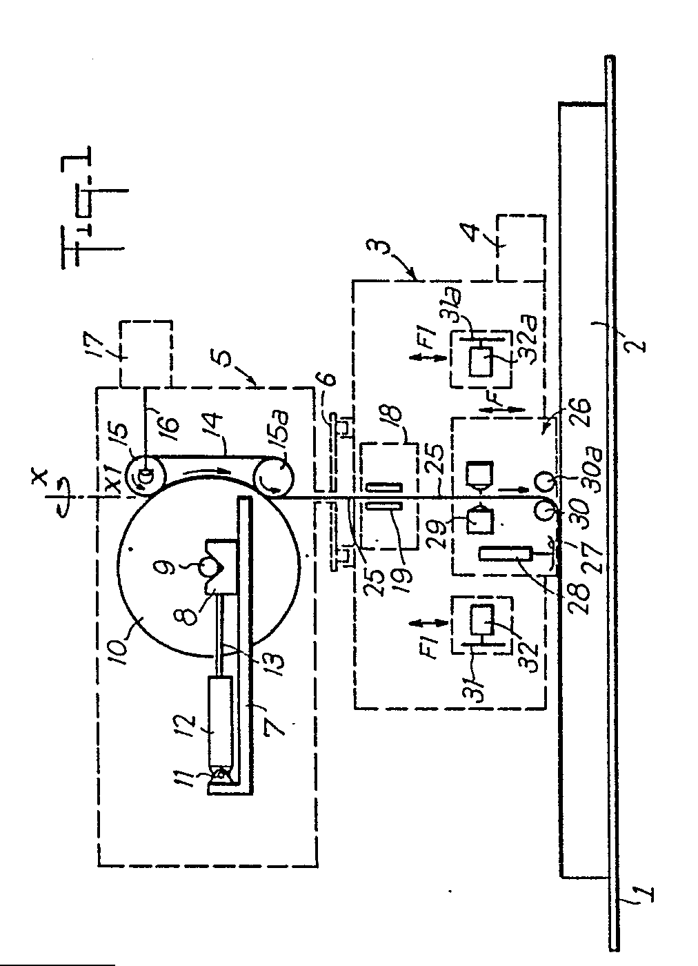
Description
La présente invention a pour objet un dispositif de matelassage de matières foliiformes.The present invention relates to a quilting device for leaf-like materials.
L'opération de matelassage consiste à superposer plusieurs plis de matière foliiforme d'une longueur donnée sur un support constitué en général d'une table. Dans ce but, on utilise un chariot nratelasseur.The quilting operation consists of superimposing several folds of leaf-like material of a given length on a support generally consisting of a table. For this purpose, a nratelasseur trolley is used.
Les principales caractéristiques d'un chariot matelasseur, pour répondre à la modernisation des moyens de production dans les ateliers de confection textile, doivent être les suivantes:
- -possibilité de matelasser différents types de matière,
- -possibilité de créer des matelas de configurations différentes,
- -pas de création de tension interne dans la matière lors de la dépose,
- -précision de la dépose sur le support,
- -rapidifé,
- -qualité de dépose (par exemple, pas de plis),
- -automatisation complète,
- -asservissement de laize centré sur l'axe médian de support.
- -possibility of padding different types of material,
- -possibility of creating mattresses of different configurations,
- - no creation of internal tension in the material during removal,
- -precision of removal on the support,
- -picked,
- -quantity of removal (for example, no folds),
- - full automation,
- -waving width centered on the median axis of support.
Les inconvénients essentiels des chariots matelasseurs actuels sont les suivants :
- -impossibilité de traiter des matières extensibles sans la mise en place d'un mécanisme spécial lourd et encombrant,
- -précision de dépose, surtout en bout très aléatoire,
- -automatisation généralement partielle et nécessitant toujours un opérateur à proximité du matelasseur pour contrôler le bon fonctionnement.
- - impossibility of processing extensible materials without the installation of a special heavy and bulky mechanism,
- - precision of removal, especially at the very random end,
- - automation generally partial and always requiring an operator near the quilter to check the correct operation.
Pour rémédier à ces inconvénients, on utilise suivant l'invention un dispositif de matelassage perfectionné.To remedy these drawbacks, an improved quilting device is used according to the invention.
Conformément à la présente invention, le dispositif comprend une table fixe sur laquelle est monté coulissant un chariot portant un rouleau de tissu monté en rotation libre sur un support et maintenu en pression contre au moins une bande élastique sans fin d'entraînement montée sur deux rouleaux disposés parallèlement et dans un plan vertical, lesdits rouleaux étant entraînés en rotation par un organe moteur asservi en position et en vitesse, le tissu étant déroulé et descendant librement verticalement pour être couché sur la table de matelassage.According to the present invention, the device comprises a fixed table on which is slidably mounted a carriage carrying a roll of fabric mounted in free rotation on a support and maintained in pressure against at least one elastic band without end of drive mounted on two rollers arranged parallel and in a vertical plane, said rollers being driven in rotation by a motor member controlled in position and speed, the fabric being unrolled and descending freely vertically to be lying on the quilting table.
Le dispositif suivant l'invention présente un effort de contact, entre le tissu et les bandes élastiques sans fin d'entraînement du rouleau de tissu, qui est réglable de façon précise et qui est indépendant du poids du rouleau de tissu.The device according to the invention has a contact force, between the fabric and the endless elastic bands for driving the fabric roll, which is precisely adjustable and which is independent of the weight of the fabric roll.
Le chargement du rouleau de tissu peut être totalement automatisé.The loading of the fabric roll can be fully automated.
L'entraînement tangentiel du rouleau de tissu permet un contrôle très précis du déroulage.The tangential drive of the fabric roll allows very precise control of the unwinding.
Enfin, avec ce dispositif, le tissu tombe de son propre poids, à la verticale du rouleau inférieur sur lequel sont montées les bandes d'entraînement et de ce fait, le tissu peut être traité directement .par les organes de mesures et de guidage.Finally, with this device, the fabric falls from its own weight, vertically from the lower roller on which the drive belts are mounted and, therefore, the fabric can be treated directly by the measuring and guiding members.
Suivant une autre caractéristique de l'invention, le chariot est muni d'un moyen d'asservissement de lisière de la laize de tissu qui est constitué de deux cellules optoélectroniques entre lesquelles passe le tissu et qui se déplacent sur une glissière disposée parallèlement au tissu, le déplacement de ces cellules étant tel que l'écartement entre elles est toujours centré sur un axe longitudinal de la table.According to another characteristic of the invention, the trolley is provided with means for controlling the edge of the fabric width which is made up of two optoelectronic cells between which the fabric passes and which move on a slide arranged parallel to the fabric , the displacement of these cells being such that the spacing between them is always centered on a longitudinal axis of the table.
Ce dispositif d'asservissement agit sur deux défauts différents :
- -défaut d'enroulement : le tissu n'est jamais parfaitement enroulë sur son tube de support,
- -variation de largeur de la laize due au procédé de fabrication du tissu.
- -winding fault: the fabric is never perfectly wound on its support tube,
- -variation of width of the width due to the fabric manufacturing process.
On obtient avec le dispositif suivant l'invention un centrage parfait de la laize sur un axe longitudinal de la machine et ceci réduit au maximum les contraintes internes du tissu.The device according to the invention provides perfect centering of the width on a longitudinal axis of the machine and this minimizes the internal stresses of the fabric.
Le dispositif suivant l'invention permet de doser très exactement les déplacements du chariot et le dévidement simultané du tissu ; en particulier, on peut faire varier les accélérations et vitesses en fonction des différents tissus et obtenir ainsi une dépose parfaite.The device according to the invention allows very precise dosing of the movements of the carriage and the simultaneous unwinding of the fabric; in particular, it is possible to vary the accelerations and speeds as a function of the different fabrics and thus obtain a perfect deposition.
La dépose se faisant sans contrainte dès le début du matelassage, il n'est plus nécessaire de tenir le tissu à son extrémité avec une pince comme c'est le cas sur les chariots matelasseurs traditionnels.The removal is done without constraint from the start of the quilting, it is no longer necessary to hold the fabric at its end with a clamp as is the case on traditional quilting trolleys.
En général, ces pinces sont encombrantes, difficiles à régler et à mettre en place.In general, these pliers are bulky, difficult to adjust and to set up.
D'autres caractéristiques et avantages de l'invention seront mieux compris à la lecture de la description qui va suivre d'un mode de réalisation et en se référant aux dessins annexés, sur lesquels
- la figure 1 est une vue en élévation d'un mode de réalisation du dispositif de matelassage de matières foliiformes suivant l'invention ;
- la figure 2 est une vue en plan du moyen d'asservissement de lisière du tissu ;
- les figures 3 à 3b sont des schémas montrant le contrôle de la position de la lisière du tissu ;
- les figures 4 à 4d sont des schémas montrant les différentes opérations du matelassage effectuées avec le dispositif suivant l'invention ;
- les figures 5 à 5d sont des schémas montrant la réalisation d'un premier type de matelassage;
- les figures 6 à 6b sont des schémas d'un deuxième type de matelassage ;
- les figures 7 à 7f sont des schémas d'un troisième type de matelassage ; et
- les figures 8 à 8d sont des schémas d'un quatrième type de matelassage.
- Figure 1 is an elevational view of an embodiment of the quilting device for leafy materials according to the invention;
- FIG. 2 is a plan view of the means for controlling the edge of the fabric;
- Figures 3 to 3b are diagrams showing the control of the position of the edge of the fabric;
- Figures 4 to 4d are diagrams showing the different operations of quilting performed with the device according to the invention;
- Figures 5 to 5d are diagrams showing the production of a first type of quilting;
- Figures 6 to 6b are diagrams of a second type of padding;
- Figures 7 to 7f are diagrams of a third type of padding; and
- Figures 8 to 8d are diagrams of a fourth type of quilting.
A la figure 1, on a représenté un organe de support constitué notamment d'une table fixe 1, sur laquelle est disposé un matelas 2 constitué de plusieurs plis superposés de matière foliiforme d'une longueur donnée, ladite table 1 étant supportée par un châssis principal non représenté au dessin sur lequel est guidé en translation par l'intermédiaire de rails un chariot matelasseur 3. Le chariot 3 est entraîné par un moteur 4 asservi en position et en vitesse de façon à contrôler très précisément tous ses déplacements. Le chariot 3 qui se déplace au-dessus du matelas de tissu 2 est muni à sa partie supérieure d'une tourelle 5 qui est montée pivotante sur le chariot suivant un axe vertical au moyen d'un palier 6. Cette tourelle 5 peut pivoter par rapport au chariot 3 autour de l'axe X-X, centré sur le point de chute du tissu, permettant ainsi de créer tous les types de matelas ainsi qu'il sera décrit ultérieurement.In Figure 1, there is shown a support member consisting in particular of a fixed table 1, on which is disposed a
La tourelle 5 comporte des glissières 7 sur lesquelles sont montés coulissants des supports 8 en V qui reçoivent un axe 9 d'un rouleau de tissu 10, l'axe 9 étant totalement libre en rotation sur les supports 8 en V.The
Sur les glissières 7 est fixé par une chape 11 le corps 12 d'un vérin dont la tige 13 est solidaire des supports 8 en V, de manière à déplacer horizontalement le rouleau de tissu pour l'amener en contact avec des bandes élastiques sans fin 14 qui assurent l'entraînement en rotation tangentiel du rouleau 10.On the
Les bandes sans fin 14 sont montées à intervalles réguliers entre-elles sur deux rouleaux 15, 15a disposés parallèlement et dans un plan vertical, à une position fixe par rapport à la tourelle 5. Au moins l'un des rouleaux 15 est relié par une transmission 16 à un moteur 17 fixé sur la tourelle et assurant l'entraînement en rotation des rouleaux et la translation des bandes sans fin 14 qui entraînent le rouleau de tissu 10 lorsque celui-ci est en contact avec lesdites bandes sous l'action du vérin 12. Le moteur 17 est asservi en position et en vitesse.The
A la partie supérieure du chariot 3 est monté un moyen d'asservissement 18 de la lisière du tissu qui permet de déposer la laize de tissu toujours centrée sur un axe longitudinal de la table 1.At the upper part of the
A cet effet, ledit moyen est constitué (figures 1 et 2) de deux cellules optoélectroniques 19, 19a qui sont fixées sur deux chariots 20, 20a se déplaçant sur une glissière 21 disposée parallèlement au tissu, lesdits chariots portant des écrous 22, 22a qui sont engagés sur une tige 23 filetée à droite et à gauche, ladite tige 23 étant montée rotative dans des paliers prévus aux extrémités de la glissière et entraînée par un moteur 24.To this end, said means consists (FIGS. 1 and 2) of two
Le déplacement des cellules 19, 19a est tel que l'écartement entre elles est toujours centré sur un axe longitudinal de la machine.The displacement of the
Les cellules 19, 19a sont disposées de telle manière que le tissu 24 passe entre elles juste à la sortie du système de déroulement.The
Les cellules agissent par l'intermédiaire d'un calculateur électronique sur un moteur (non représenté) permettant le déplacement transversal de la tourelle 5 par l'intermédiaire des glissières 6. Ainsi, dès que les cellules enregistrent une modification de largeur de laize, le tissu est déplacé de façon à être ramené dans un axe longitudinal de la machine.The cells act by means of an electronic computer on a motor (not shown) allowing the transverse displacement of the
A la base du chariot 3 est monté un moyen de dépose du tissu 26 qui est mobile verticalement suivant la double flèche F et actionné par un organe moteur asservi en position. Ce moyen permet lors de la descente verticale du tissu de coucher celui-ci sur la table 1 de matelassage.At the base of the
Ce moyen de dépose du tissu 26 comprend un palpeur 27 actionné par un vérin 28 et qui permet de positionner le moyen de dépose du tissu 26 à une hauteur constante par rapport au pli supérieur du matelas 2.This means for depositing the
Le moyen de dépose comporte à sa partie supérieure une cellule optoélectronique 29 permettant d'arrêter très précisément l'extrémité du tissu 25 à une hauteur donnée dépendant de la position du palpeur .27.The removal means comprises at its upper part an
A la base du moyen de dépose 26 sont disposés des éléments 30, 30a pour dévier la trajectoire du tissu 25 et éliminer les plis. Ces éléments sont susceptibles d'être écartés pour laisser le passage libre lorsque le tissu descend entre lesdits éléments. On utilise deux éléments 30, 30a pour pouvoir faire la dépose dans les deux sens.At the base of the depositing means 26 are arranged
Ces éléments peuvent être constitutés de rouleaux bananes, de rouleaux avec des jets d'air comprimé, etc.These elements can consist of banana rollers, rollers with jets of compressed air, etc.
De part et d'autre du moyen de dépose sont montés deux organes de découpe du tissu 31, 31 a constitués notamment par des couteaux circulaires entraînés en rotation par des moteurs 32, 32a, chaque couteau, et son moteur, étant monté sur une glissière disposée transversalement et parallèlement au matelas 2.On either side of the removal means are mounted two fabric cutting members 31, 31a constituted in particular by circular knives driven in rotation by
Chaque couteau est décalé par rapport au point de chute du tissu. Il faut donc faire avancer le chariot 3 au-delà de la fin du matelas d'une valeur égale au décalage de façon que le couteau soit au-dessus de l'extrémité du matelas 2.Each knife is offset from the drop point of the fabric. It is therefore necessary to advance the
La glissière supportant le couteau 31, 31 a est susceptible de se déplacer verticalement suivant la flèche F1, de telle sorte qu'en abaissant l'ensemble de coupe, celui-ci vient en appui sur le matelas 2 et le couteau coupe le pli de tissu au ras de l'extrémité du matelas.The slide supporting the knife 31, 31 a is capable of moving vertically along the arrow F1, so that by lowering the cutting assembly, it comes to bear on the
Le dispositif de matelassage suivant l'invention fonctionne de la manière suivante :
- comme représenté à la figure 4, le rouleau de tissu, avec son axe central 9, (figure 1) est posé sur les supports en V 8, le vérin 12 se trouvant en position rentrée.
- as shown in FIG. 4, the fabric roll, with its central axis 9, (FIG. 1) is placed on the V-shaped supports 8, the
jack 12 being in the retracted position.
On inverse la pression dans le vérin 12 de telle sorte que les supports 8 coulissent en direction des bandes sans fin 14 pour amener le rouleau de tissu 10 en contact avec celles-ci. La pression de l'air comprimé dans le vérin est réglée de façon à ne pas obtenir un écrasement du tissu ou une trop grande élongation des bandes sans fin 14.The pressure is reversed in the
Dès cet instant, le tissu étant en contact des bandes 14 et des rouleaux 15, 15a, il suffit d'alimenter le moteur 17 pour dévider le tissu. En raison de l'entraînement tangentiel du tissu, on peut donc contrôler précisément la longueur de tissu déroulé.From this moment, the fabric being in contact with the
Le chariot 3 étant immobilisé à un endroit tel que le point de chute du tissu soit situé exactement au-dessus du début du matelas 2 (figure 4a), le tissu est déroulé lentement et il passe à travers les cellules 19, 19a d'asservissement de lisière jusqu'à ce qu'il parvienne devant la cellule optoélectronique 29.The
Les éléments 30, 30a sont en position écartée. On connaît exactement la distance d entre la cellule 29 et la surface supérieure du matelas qui est indiquée par le palpeur 27.The
Ensuite, on fait descendre le tissu d'une valeur correspondant à cette distance. Le tissu arrive alors juste au contact de l'angle supérieur du matelas 2 (figure 4b).Then, the fabric is lowered by a value corresponding to this distance. The fabric then comes just in contact with the upper corner of the mattress 2 (Figure 4b).
Les éléments de guidage 30, 30a sont alors rapprochés l'un de l'autre.The
A partir de cette position, le matelassage peut être réalisé. Le chariot 3 se déplace et si- multénément, en parfait synchronisme, le tissu 25 se déroule afin d'être déposé sur le matelas 2 sans contrainte (figure 4c).From this position, quilting can be carried out. The
Au cours du déplacement du chariot 3 pour procéder au matelassage, le moyen d'asservissement de lisière assure le centrage du tissu sur la table.During the movement of the
A cet effet et au début de l'opération, les cellules optoélectroniques 19, 19a sont écartées au maximum (figure 2) et ensuite, on fait descendre le tissu entre lesdites cellules.To this end and at the start of the operation, the
On rapproche lentement les cellules 19, 19a et dès que l'une d'entre elles rencontre le tissu, le rouleau 10 de tissu est déplacé en sens opposé - (figures 3a, 3b) pour ramener le tissu dans la position de centrage,représentée à la figure 3.The
Dès que les deux cellules 19, 19a sont couvertes (figure 3), elles sont immobilisées, le calculateur compare les surfaces couvertes et agit sur le tissu de façon à les équilibrer.As soon as the two
Ce moyen permet de mesurer en temps réel la largeur de la laize et cette valeur peut être communiquée au calculateur central et être utilisée comme paramètre de gestion et de contrôle du fonctionnement de la machine.This means allows the width of the width to be measured in real time and this value can be communicated to the central computer and used as a parameter for managing and controlling the operation of the machine.
Lorsqu'un nouveau pli de tissu a été déposé sur le matelas 2, l'un des ensembles de coupe est abaissé et vient en appui sur le matelas (figure 4d). Le couteau 31 coupe le pli de tissu au ras de l'extrémité du matelas.When a new fold of fabric has been deposited on the
Dès que la coupe est terminée, le tissu est réenroulé jusqu'au niveau de la cellule 29, le chariot 3 est déplacé au-dessus de l'autre extrémité du matelas 2 et on procède au dépôt d'un nouveau pli.As soon as the cutting is finished, the fabric is rewound up to the level of the
Aux figures 5 à 5d, on a représenté un premier type de matelassage dans lequel le motif du tissu se trouve toujours orienté à la partie supérieure du matelas, les plis 33 et 33a étant disposés comme représenté à la figure 5a et le déroulement du tissu s'effectuant comme représenté à la figure 5.In Figures 5 to 5d, there is shown a first type of quilting in which the pattern of the fabric is always oriented at the top of the mattress, the
Au cours d'un premier déplacement aller du chariot 3, un premier pli 33 est déposé. sur le matelas (figure 5b) alors que le retour après la coupe du pli 33 s'effectue à vide (figure 5c). Ensuite, le chariot 3 effectue un deuxième déplacement aller au cours duquel il dépose un second pli 33a sur le pli 33 (figure 5d). Ce déplacement après une coupe en bout de matelas est suivi d'un deuxième retour à vide (figure 5c) et ainsi de suite.During a first forward movement of the
Aux figures 6 à 6b, on a représenté un matelassage en accordéon dans lequel les motifs du tissu sont disposés en regard l'un de l'autre (figure 6).In Figures 6 to 6b, there is shown an accordion quilting in which the patterns of the fabric are arranged opposite one another (Figure 6).
Dans ce cas, le chariot 3 effectue un premier trajet aller au cours duquel il dépose un pli 34 sur le matelas (figure 6a). Après une coupe en bout du matelas, le chariot effectue un trajet de retour au cours duquel il dépose un second pli 34a sur le pli 34 (figure 6b). L'opération se répète ainsi après une coupe des plis à chaque extrémité du matelas.In this case, the
Aux figures 7 à 7f, on a représenté un troisième type de matelassage dans lequel le chariot effectue un premier déplacement aller (figure 7a) au cours duquel un pli 35 est déposé sur le matelas. Après une coupe en bout de tissu, le chariot 3 revient à vide à son point de départ (figure 7b) où l'on procède à une rotation de la tourelle 5 de 180° (figure 7c).In FIGS. 7 to 7f, a third type of quilting is shown in which the carriage makes a first outward movement (FIG. 7a) during which a
Le chariot effectue alors un deuxième déplacement aller (figure 7d) au cours duquel il dépose un pli de tissu 36 sur le pli 35 et après découpe en bout un deuxième retour à vide (figure 7e).The carriage then performs a second forward movement (FIG. 7d) during which it deposits a ply of
Ensuite, la tourelle 5 subit de nouveau une rotation de 180° (figure 7f).Then, the
Aux figures 8 à 8d, on a représenté un quatrième type de matelassage dans lequel un premier pli 36 est déposé sur le matelas au cours d'un premier aller (figure 8a).In Figures 8 to 8d, there is shown a fourth type of padding in which a
On procède après une coupe en bout à une rotation de la tourelle 5 (figure 8b). Au cours du déplacement de retour (figure 8c) du chariot 3 un pli 36a est formé sur le pli 36 et ensuite on procède à la rotation de la tourelle 5 de 180° - (figure 8d).After a cut at the end, the
Bien entendu, la description n'est pas limitative et l'homme de l'art pourra y apporter des modifications sans sortir pour cela du domaine de l'invention.Of course, the description is not limiting and those skilled in the art may make modifications to it without departing from the scope of the invention.
Claims (9)
Priority Applications (1)
| Application Number | Priority Date | Filing Date | Title |
|---|---|---|---|
| AT86400705T ATE65234T1 (en) | 1985-04-04 | 1986-04-02 | CLOTH LAYING MACHINE. |
Applications Claiming Priority (2)
| Application Number | Priority Date | Filing Date | Title |
|---|---|---|---|
| FR8505184 | 1985-04-04 | ||
| FR8505184A FR2579962B1 (en) | 1985-04-04 | 1985-04-04 |
Publications (3)
| Publication Number | Publication Date |
|---|---|
| EP0200604A2 true EP0200604A2 (en) | 1986-11-05 |
| EP0200604A3 EP0200604A3 (en) | 1988-12-21 |
| EP0200604B1 EP0200604B1 (en) | 1991-07-17 |
Family
ID=9317971
Family Applications (1)
| Application Number | Title | Priority Date | Filing Date |
|---|---|---|---|
| EP86400705A Expired - Lifetime EP0200604B1 (en) | 1985-04-04 | 1986-04-02 | Cloth spreading apparatus |
Country Status (6)
| Country | Link |
|---|---|
| US (1) | US4708331A (en) |
| EP (1) | EP0200604B1 (en) |
| JP (1) | JPS61230936A (en) |
| AT (1) | ATE65234T1 (en) |
| DE (1) | DE3680234D1 (en) |
| FR (1) | FR2579962B1 (en) |
Cited By (6)
| Publication number | Priority date | Publication date | Assignee | Title |
|---|---|---|---|---|
| EP0322644A3 (en) * | 1987-12-24 | 1990-04-18 | Krauss U. Reichert Gmbh + Co. Kg Spezialmaschinenfabrik | Process and fabric plaiting machine for accurately positioning the leading edge of a web-like fabric |
| DE3901299A1 (en) * | 1989-01-18 | 1990-07-19 | Guenther Sieg | FABRIC LAYING MACHINE |
| EP0322645A3 (en) * | 1987-12-24 | 1990-10-10 | Krauss U. Reichert Gmbh + Co. Kg Spezialmaschinenfabrik | Laying machine |
| FR2658177A1 (en) * | 1990-02-09 | 1991-08-16 | Jice Automat Soc | Device for piling and cutting of fabric |
| FR2664248A1 (en) * | 1990-07-04 | 1992-01-10 | Jice Automat Soc | Device for unwinding a roll of fabric |
| EP0504554A3 (en) * | 1991-02-15 | 1992-12-02 | Krauss U. Reichert Gmbh + Co. Kg Spezialmaschinenfabrik | Method for arranging cut pieces and device for spreading cloth |
Families Citing this family (7)
| Publication number | Priority date | Publication date | Assignee | Title |
|---|---|---|---|---|
| DE3668311D1 (en) * | 1986-11-03 | 1990-02-22 | Raco Maschinenfabrik Gmbh & Co | LAYING DEVICE. |
| IT1215017B (en) * | 1986-11-04 | 1990-01-31 | Fk Arna S R L | WAGON WITH TOWER SUPPORT FOR ROLLS OF CLOTHES TO BE SPREAD ON THE PALLET OF AUTOMATIC SPREADERS |
| JPH0699076B2 (en) * | 1990-08-10 | 1994-12-07 | 株式会社エヌシーエー | Anti-end payout level adjusting device of the spreading machine |
| US5447296A (en) * | 1993-05-26 | 1995-09-05 | Cox; Michael A. | Cloth spreading system |
| DE102005016745A1 (en) * | 2005-04-11 | 2006-10-12 | Saurer Gmbh & Co. Kg | Method and device for depositing a flexible material web |
| JP2012046839A (en) * | 2010-08-26 | 2012-03-08 | Precision Fukuhara Works Ltd | Control method of knitted fabric guide and swing-and-drop winding device using the method |
| CN107337022A (en) * | 2017-07-31 | 2017-11-10 | 中信戴卡股份有限公司 | A kind of non-woven fabrics automatic laying device for laying |
Family Cites Families (22)
| Publication number | Priority date | Publication date | Assignee | Title |
|---|---|---|---|---|
| US2118556A (en) * | 1936-03-11 | 1938-05-24 | Murray Corp | Traveling reel |
| US2544951A (en) * | 1948-10-05 | 1951-03-13 | Lassus Harold Joseph De | Cloth spreading machine |
| FR1146416A (en) * | 1955-09-24 | 1957-11-12 | Rimoldi C Spa Virginio | Superimposed ply fabric unrolling machine |
| GB794463A (en) * | 1955-09-24 | 1958-05-07 | Rimoldi C Spa Virginio | Folding machine for piling fabric in superposed folds preparatory to simultaneous cutting of the various folds according to a pattern |
| US3181859A (en) * | 1962-12-31 | 1965-05-04 | Pennway Garment Company | Side register means for cloth spreading apparatus |
| US3400927A (en) * | 1966-04-04 | 1968-09-10 | Cutters Machine Co Inc | Cloth spreading machine |
| GB1264533A (en) * | 1969-02-28 | 1972-02-23 | ||
| US3776542A (en) * | 1969-09-12 | 1973-12-04 | Cutters Machine Co Inc | Electrically controlled cloth spreading machine |
| US3645524A (en) * | 1970-06-08 | 1972-02-29 | Panther Machine Corp | Edge alignment assembly for cloth-spreading machine |
| US3817513A (en) * | 1972-05-16 | 1974-06-18 | Cutters Machine Co Inc | Winding mechanism for cloth spreading machine |
| FR2223289B1 (en) * | 1973-03-30 | 1978-02-17 | Stumpf Guenter | |
| GB1412227A (en) * | 1973-03-30 | 1975-10-29 | Stumpf G | Fabric layering machines |
| DE2507453C2 (en) * | 1975-02-21 | 1976-11-18 | Pfaff Ind Masch | FABRIC MACHINE |
| IT1096535B (en) * | 1978-06-09 | 1985-08-26 | Ima Spa | EQUIPMENT FOR SPREADING FABRICS IN LAYERS OVERLAPED ON BENCHES, FOR GARMENT PACKAGING INDUSTRIES |
| GB2051903A (en) * | 1979-06-04 | 1981-01-21 | Cutters Exchange | Cloth laying machine |
| IT1209232B (en) * | 1980-06-18 | 1989-07-16 | Rockwell Rimoldi Spa | FEEDER DEVICE FOR ROLLED PIECES FOR BANDING MACHINES. |
| JPS5847761A (en) * | 1981-09-09 | 1983-03-19 | Keiko Tagawa | Piece spreading apparatus |
| JPS58139945A (en) * | 1982-02-12 | 1983-08-19 | Achilles Corp | Takeup roller for filmy material |
| JPS5921155U (en) * | 1982-07-30 | 1984-02-08 | 株式会社クボタ | Forward/reverse switching device for bevel gear transmission |
| US4477065A (en) * | 1983-09-19 | 1984-10-16 | Cutters Exchange, Inc. | Belt feed apparatus for cloth spreading machine |
| EP0158281B1 (en) * | 1984-04-13 | 1988-07-20 | Krauss u. Reichert GmbH + Co. KG Spezialmaschinenfabrik | Fabrics lay-down machine |
| US4519595A (en) * | 1984-07-10 | 1985-05-28 | N.C.A. Co., Ltd. | Apparatus for unwinding fabric from a roll |
-
1985
- 1985-04-04 FR FR8505184A patent/FR2579962B1/fr not_active Expired
-
1986
- 1986-04-02 AT AT86400705T patent/ATE65234T1/en not_active IP Right Cessation
- 1986-04-02 EP EP86400705A patent/EP0200604B1/en not_active Expired - Lifetime
- 1986-04-02 DE DE8686400705T patent/DE3680234D1/en not_active Expired - Lifetime
- 1986-04-04 JP JP61076874A patent/JPS61230936A/en active Pending
- 1986-04-04 US US06/848,086 patent/US4708331A/en not_active Expired - Lifetime
Cited By (8)
| Publication number | Priority date | Publication date | Assignee | Title |
|---|---|---|---|---|
| EP0322644A3 (en) * | 1987-12-24 | 1990-04-18 | Krauss U. Reichert Gmbh + Co. Kg Spezialmaschinenfabrik | Process and fabric plaiting machine for accurately positioning the leading edge of a web-like fabric |
| US4946150A (en) * | 1987-12-24 | 1990-08-07 | Krauss U. Reichert Gmbh & Co. | Method and fabric laying machine for exact positioning of a leading edge of a fabric web |
| EP0322645A3 (en) * | 1987-12-24 | 1990-10-10 | Krauss U. Reichert Gmbh + Co. Kg Spezialmaschinenfabrik | Laying machine |
| DE3901299A1 (en) * | 1989-01-18 | 1990-07-19 | Guenther Sieg | FABRIC LAYING MACHINE |
| EP0379205A1 (en) * | 1989-01-18 | 1990-07-25 | Rüffer, Peter | Cloth-spreading machine |
| FR2658177A1 (en) * | 1990-02-09 | 1991-08-16 | Jice Automat Soc | Device for piling and cutting of fabric |
| FR2664248A1 (en) * | 1990-07-04 | 1992-01-10 | Jice Automat Soc | Device for unwinding a roll of fabric |
| EP0504554A3 (en) * | 1991-02-15 | 1992-12-02 | Krauss U. Reichert Gmbh + Co. Kg Spezialmaschinenfabrik | Method for arranging cut pieces and device for spreading cloth |
Also Published As
| Publication number | Publication date |
|---|---|
| JPS61230936A (en) | 1986-10-15 |
| ATE65234T1 (en) | 1991-08-15 |
| EP0200604A3 (en) | 1988-12-21 |
| FR2579962A1 (en) | 1986-10-10 |
| US4708331A (en) | 1987-11-24 |
| FR2579962B1 (en) | 1987-07-03 |
| DE3680234D1 (en) | 1991-08-22 |
| EP0200604B1 (en) | 1991-07-17 |
Similar Documents
| Publication | Publication Date | Title |
|---|---|---|
| EP0200604B1 (en) | Cloth spreading apparatus | |
| EP0056353B1 (en) | Automatic machine for cutting, folding and preparing packages of sheets delivered from wound webs | |
| CH691156A5 (en) | Paper web feed for cigarette making machine has tension adjuster with drive roller and up and downstream tensioners to control feed | |
| FR2673860A1 (en) | MOTORIZED BALL TABLE WITH CROSS MOVEMENTS FOR THE ORTHOGONAL SORTING OF FLAT LOADS. | |
| FR2553330A1 (en) | HIGH PRESSURE FLUID JET WEB CUTTING MACHINE | |
| FR2705655A1 (en) | Machine for winding-deposited at the simultaneous contact of a plurality of individual threads. | |
| FR2486022A1 (en) | METHOD AND APPARATUS FOR PACKAGING | |
| FR2565897A1 (en) | TABLECLOTH TENSIONING DEVICE FOR A MACHINE FOR MANUFACTURING BAGS OF THERMOPLASTIC MATERIAL | |
| EP3307662B1 (en) | Creel for fibre bobbin | |
| FR2531941A1 (en) | MACHINE FOR CUTTING PARTS INTO BAND MATERIAL | |
| FR2620117A1 (en) | DIVIDING AND REENROUTING STRIP MACHINES | |
| FR2472044A1 (en) | METHOD AND DEVICE FOR LOCALLY INSERTING AN ELASTIC TAPE IN AN ADAPTABLE COVER SHEET AROUND A MATTRESS | |
| BE1006529A6 (en) | A ciree canvas process. | |
| EP0707527A1 (en) | Cutting machine using a rotary wheel for cutting a flexible material consisting of a single sheet or a small mat of sheets, and method for adjusting said machine | |
| EP0156738A1 (en) | Device for winding a fabric during the various manufacturing stages | |
| EP0411982A1 (en) | Method and machine for helically depositing a film web on the vertical sides of a palettized load | |
| FR2599350A1 (en) | APPARATUS AND METHOD FOR PERFORMING A WORK ON A ROLLED TISSUE ON A DEBIT ROLLER | |
| EP0119147B1 (en) | Method and device for spreading lengths of fabric | |
| EP1697244A1 (en) | Automatic removal device for changing roll in machines for the production of rolls of paper or similar | |
| FR2484975A1 (en) | FEEDING DEVICE FOR FOLDING MACHINES | |
| EP0252844B1 (en) | Automatic apparatus for treating, and in particular for cutting, web material | |
| FR2651804A1 (en) | APPARATUS FOR PROCESSING A STACK OF CLOTHING FOR SEWING. | |
| BE823679A (en) | PLASTIC BAG FORMING MACHINE | |
| FR2478340A1 (en) | Web feeder for automatic web working machine - monitors movement of rail coupled to web displacement to stop web in defined position | |
| EP0502798B1 (en) | Installation for unwinding a web material such as a textile web in order to inspect it and for winding it to a wound package of fixed length |
Legal Events
| Date | Code | Title | Description |
|---|---|---|---|
| PUAI | Public reference made under article 153(3) epc to a published international application that has entered the european phase |
Free format text: ORIGINAL CODE: 0009012 |
|
| AK | Designated contracting states |
Kind code of ref document: A2 Designated state(s): AT BE CH DE FR GB IT LI LU NL SE |
|
| PUAB | Information related to the publication of an a document modified or deleted |
Free format text: ORIGINAL CODE: 0009199EPPU |
|
| RA1 | Application published (corrected) |
Date of ref document: 19861210 Kind code of ref document: A2 |
|
| PUAL | Search report despatched |
Free format text: ORIGINAL CODE: 0009013 |
|
| AK | Designated contracting states |
Kind code of ref document: A3 Designated state(s): AT BE CH DE FR GB IT LI LU NL SE |
|
| 17P | Request for examination filed |
Effective date: 19890217 |
|
| 17Q | First examination report despatched |
Effective date: 19900921 |
|
| GRAA | (expected) grant |
Free format text: ORIGINAL CODE: 0009210 |
|
| AK | Designated contracting states |
Kind code of ref document: B1 Designated state(s): AT BE CH DE FR GB IT LI LU NL SE |
|
| PG25 | Lapsed in a contracting state [announced via postgrant information from national office to epo] |
Ref country code: SE Effective date: 19910717 |
|
| REF | Corresponds to: |
Ref document number: 65234 Country of ref document: AT Date of ref document: 19910815 Kind code of ref document: T |
|
| REF | Corresponds to: |
Ref document number: 3680234 Country of ref document: DE Date of ref document: 19910822 |
|
| GBT | Gb: translation of ep patent filed (gb section 77(6)(a)/1977) | ||
| ITF | It: translation for a ep patent filed | ||
| PG25 | Lapsed in a contracting state [announced via postgrant information from national office to epo] |
Ref country code: LU Free format text: LAPSE BECAUSE OF NON-PAYMENT OF DUE FEES Effective date: 19920430 Ref country code: LI Effective date: 19920430 Ref country code: CH Effective date: 19920430 Ref country code: BE Effective date: 19920430 |
|
| PLBE | No opposition filed within time limit |
Free format text: ORIGINAL CODE: 0009261 |
|
| STAA | Information on the status of an ep patent application or granted ep patent |
Free format text: STATUS: NO OPPOSITION FILED WITHIN TIME LIMIT |
|
| 26N | No opposition filed | ||
| BERE | Be: lapsed |
Owner name: S.A. LECTRA SYSTEMES Effective date: 19920430 |
|
| REG | Reference to a national code |
Ref country code: CH Ref legal event code: PL |
|
| PGFP | Annual fee paid to national office [announced via postgrant information from national office to epo] |
Ref country code: NL Payment date: 19930430 Year of fee payment: 8 |
|
| PGFP | Annual fee paid to national office [announced via postgrant information from national office to epo] |
Ref country code: AT Payment date: 19940321 Year of fee payment: 9 |
|
| PG25 | Lapsed in a contracting state [announced via postgrant information from national office to epo] |
Ref country code: NL Effective date: 19941101 |
|
| NLV4 | Nl: lapsed or anulled due to non-payment of the annual fee | ||
| PG25 | Lapsed in a contracting state [announced via postgrant information from national office to epo] |
Ref country code: AT Effective date: 19950402 |
|
| PGFP | Annual fee paid to national office [announced via postgrant information from national office to epo] |
Ref country code: GB Payment date: 19960326 Year of fee payment: 11 |
|
| PGFP | Annual fee paid to national office [announced via postgrant information from national office to epo] |
Ref country code: DE Payment date: 19960422 Year of fee payment: 11 |
|
| PGFP | Annual fee paid to national office [announced via postgrant information from national office to epo] |
Ref country code: FR Payment date: 19960429 Year of fee payment: 11 |
|
| PG25 | Lapsed in a contracting state [announced via postgrant information from national office to epo] |
Ref country code: GB Effective date: 19970402 |
|
| GBPC | Gb: european patent ceased through non-payment of renewal fee |
Effective date: 19970402 |
|
| PG25 | Lapsed in a contracting state [announced via postgrant information from national office to epo] |
Ref country code: FR Free format text: LAPSE BECAUSE OF NON-PAYMENT OF DUE FEES Effective date: 19971231 |
|
| PG25 | Lapsed in a contracting state [announced via postgrant information from national office to epo] |
Ref country code: DE Free format text: LAPSE BECAUSE OF NON-PAYMENT OF DUE FEES Effective date: 19980101 |
|
| REG | Reference to a national code |
Ref country code: FR Ref legal event code: ST |
|
| PG25 | Lapsed in a contracting state [announced via postgrant information from national office to epo] |
Ref country code: IT Free format text: LAPSE BECAUSE OF NON-PAYMENT OF DUE FEES;WARNING: LAPSES OF ITALIAN PATENTS WITH EFFECTIVE DATE BEFORE 2007 MAY HAVE OCCURRED AT ANY TIME BEFORE 2007. THE CORRECT EFFECTIVE DATE MAY BE DIFFERENT FROM THE ONE RECORDED. Effective date: 20050402 |