EP0200239A2 - Banc de filtres numériques de polyphase à réduction d'échantillonnage maximale - Google Patents
Banc de filtres numériques de polyphase à réduction d'échantillonnage maximale Download PDFInfo
- Publication number
- EP0200239A2 EP0200239A2 EP86200438A EP86200438A EP0200239A2 EP 0200239 A2 EP0200239 A2 EP 0200239A2 EP 86200438 A EP86200438 A EP 86200438A EP 86200438 A EP86200438 A EP 86200438A EP 0200239 A2 EP0200239 A2 EP 0200239A2
- Authority
- EP
- European Patent Office
- Prior art keywords
- filter bank
- clock reduction
- complex
- signals
- subband signals
- Prior art date
- Legal status (The legal status is an assumption and is not a legal conclusion. Google has not performed a legal analysis and makes no representation as to the accuracy of the status listed.)
- Granted
Links
Images
Classifications
-
- H—ELECTRICITY
- H03—ELECTRONIC CIRCUITRY
- H03H—IMPEDANCE NETWORKS, e.g. RESONANT CIRCUITS; RESONATORS
- H03H17/00—Networks using digital techniques
- H03H17/02—Frequency selective networks
- H03H17/0248—Filters characterised by a particular frequency response or filtering method
- H03H17/0264—Filter sets with mutual related characteristics
- H03H17/0266—Filter banks
-
- H—ELECTRICITY
- H03—ELECTRONIC CIRCUITRY
- H03H—IMPEDANCE NETWORKS, e.g. RESONANT CIRCUITS; RESONATORS
- H03H17/00—Networks using digital techniques
- H03H17/02—Frequency selective networks
- H03H17/06—Non-recursive filters
- H03H17/0621—Non-recursive filters with input-sampling frequency and output-delivery frequency which differ, e.g. extrapolation; Anti-aliasing
-
- H—ELECTRICITY
- H04—ELECTRIC COMMUNICATION TECHNIQUE
- H04B—TRANSMISSION
- H04B1/00—Details of transmission systems, not covered by a single one of groups H04B3/00 - H04B13/00; Details of transmission systems not characterised by the medium used for transmission
- H04B1/66—Details of transmission systems, not covered by a single one of groups H04B3/00 - H04B13/00; Details of transmission systems not characterised by the medium used for transmission for reducing bandwidth of signals; for improving efficiency of transmission
- H04B1/667—Details of transmission systems, not covered by a single one of groups H04B3/00 - H04B13/00; Details of transmission systems not characterised by the medium used for transmission for reducing bandwidth of signals; for improving efficiency of transmission using a division in frequency subbands
-
- H—ELECTRICITY
- H03—ELECTRONIC CIRCUITRY
- H03H—IMPEDANCE NETWORKS, e.g. RESONANT CIRCUITS; RESONATORS
- H03H2218/00—Indexing scheme relating to details of digital filters
- H03H2218/04—In-phase and quadrature [I/Q] signals
Definitions
- the invention relates to a digital analysis-synthesis filter bank according to the preamble of patent claim 1.
- Digital filter banks can be used for the spectral splitting of an input signal supplied to them into subband signals, in particular for the transmission, storage and processing of signals.
- the subband signals generated in this way are encoded and / or processed. Due to the reduced bandwidth of the subband signals generated by means of the digital filter bank, the subband signals can be represented with a reduced sampling frequency according to the sampling theorem. As a result, both the computing effort for the analysis filter bank and the effort for the transmission, storage and processing of the subband signals can be reduced accordingly.
- the sampling frequency must be increased in a synthesis filter bank in order to reconstruct or synthesize an output signal from the subband signals.
- an interpolation of the subband signals is effected and the interpolated subband signals generated in this way are additively superimposed on the output signal.
- the maximum clock reduction results from the bandwidth of the subband signals.
- Fa the sampling frequency of the input signal
- M the number of channels
- the M-channel filter bank produced in this way has the disadvantage that, on the one hand, a relatively high outlay is required for the total of the 2nd (M-1) filters, and on the other hand, the cascading of 1d (M) partial filters in each case results in a high signal delay.
- the polyphase filter bank is often used, which requires less circuitry compared to the tree structure mentioned above.
- a multi-channel filter bank is known, which is created by combining a digital polyphase network with a processor for Discrete Fourier Transform (DFT).
- DFT Discrete Fourier Transform
- the invention has for its object to design a known from DE-OS 31 18 473 digital analysis-synthesis filter bank so that even in the case of maximum clock reduction, the disturbing refolding distortions are compensated.
- the digital analysis-synthesis filter bank according to the invention has the advantage that complex poly-phase filter banks with maximum clock reduction can be realized by the modified two-stage clock reduction used.
- the disruptive refolding components that occur can be easily compensated for in the synthesis filtering.
- the embodiment of the invention specified in claim 2 has the advantage that symmetry properties of the DFT can be exploited. With a single DFT transformation, the cos and sin transformation of two different input vectors can be calculated simultaneously.
- Embodiment has the advantage that the transformation length is reduced to M / 2.
- the digital analysis-synthesis filter bank according to the invention can advantageously be used in the subband encoders of a digital radio transmission system.
- the subband coding of known digital radio transmission systems is based on the principle of QMF filters cascaded in a tree structure (see “Multirate Digital Signal Processing” by Ronald E. Crochiere, Prentice-Hall).
- the advantage of this method is that the refolding distortions which arise in the coder due to undersampling are compensated for in the interpolation filtering in the decoder.
- PPN poly-phase network filter banks
- the QMF method of the quadrature mirror condition known for half-band filters can be transferred to the PPN filter bank.
- the computing time required for coding and decoding the subband signals must be added. If the number of channels is doubled, this value must also be doubled.
- the subband encoder with the digital Ana subband encoder according to the invention with the digital analysis-synthesis filter bank according to the invention has a clear advantage over the various RELP coder variants.
- the adaptive bit allocation to the individual bands is carried out similarly to the method known from DE-OS 31 18 473.
- the first bit is assigned to the channel with maximum power.
- the power of this channel is then divided by 4 and the next bit is assigned to the channel that has the highest power. This process is repeated until all bits have been assigned.
- the actual bit allocation does not have to be communicated to the decoder, since this can be determined from the secondary information transmitted.
- a total of four processors are required for encoders and decoders (e.g. integrated signal processor NEC ⁇ PD 7720).
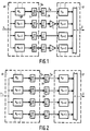
- the analysis filter bank AF splits the input signal x into complex subband signals, which are undersampled in a subsequent device U, by means of complex bandpasses BP arranged in parallel.
- a polyphase network filter bank AF PPN filter bank
- the M occurring complex subband signals x) J. are complex valued according to the equation
- the subsampler UA further reduces the data rate by a factor of 2 according to the following equation where x * ⁇ (i) denotes the conjugate complex values of the sequence x ⁇ (i).
- the further clock reduction of the M-complex subband signals x u takes place by offset subsampling - (complex clock reduction) of the real and imaginary part signals a ⁇ (i) and b ⁇ (i).
- the second stage of the clock reduction by a factor of 2 can be taken into account immediately when implementing the analysis filter bank AF by designing the DFT processor in such a way that it only calculates the respectively required values a ⁇ (i) and b ⁇ (i) .
- a synthesis filter bank SF As shown in FIG. 1, at the input of a synthesis filter bank SF, the sign of every second channel is inverted by means of a device I, that is to say all the odd-numbered channels.
- the subband signals y ⁇ (i) assume only real or only imaginary values at any time i.
- the cut-off limit of the filter bank's prototype low-pass filter fulfills the condition specified in the following equation: and the blocking attenuation 20 log ( ⁇ ) is sufficiently high.
- sufficiently high means that the signal components which are subjected to the blocking attenuation can be neglected.
- this condition is fulfilled, whereby according to equation (4) a 50% spectral overlap of adjacent filter bank channels is permissible. The disturbing refolding distortions which occur at the maximum clock reduction and which occur in each case between adjacent channels are compensated for in the synthesis filtering.
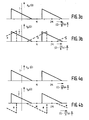
- the second stage of the clock reduction according to the invention is described and explained in more detail with reference to the subband signals shown in FIG. 3.
- the complex subband signal x ⁇ (i) shown in FIG. 3a is converted into the spectrum shown in FIG. 2b during an undersampling according to equation (2).
- the conjugate complex time signal x * (i) corresponds to the mirrored, conjugate complex frequency spectrum, which is shifted spectrally by the normalized frequency w by modulation with (-1) (see equation (2)). Due to the mirroring and shifting, the interfering refolding components during synthesis filtering can be compensated for by alternating sign reversals for every second subband signal. Because the mirroring creates an interaction between adjacent filters of the analysis and synthesis filter banks AF and SF, a compensation mechanism becomes effective between two adjacent channels.
- FIG. 2 shows a further embodiment of the digital analysis / synthesis filter bank according to the invention.
- the analysis filter bank known from DE-OS 31 18 473 is used for the first stage of the clock reduction.
- the subband signals x ⁇ of adjacent channels are complementarily undersampled by a factor of 2, in accordance with the following equation:
- the subsampler is designated with a letter A (correspondingly designated UB for equation (5b)).
- the different treatment of the odd-numbered or even-numbered channels (subband signals) can also be interchanged.
Landscapes
- Engineering & Computer Science (AREA)
- Computer Hardware Design (AREA)
- Mathematical Physics (AREA)
- Physics & Mathematics (AREA)
- Computer Networks & Wireless Communication (AREA)
- Signal Processing (AREA)
- Compression, Expansion, Code Conversion, And Decoders (AREA)
- Transmission Systems Not Characterized By The Medium Used For Transmission (AREA)
- Networks Using Active Elements (AREA)
- Complex Calculations (AREA)
- Investigating Or Analysing Biological Materials (AREA)
- Analogue/Digital Conversion (AREA)
- Analysing Materials By The Use Of Radiation (AREA)
- Color Television Image Signal Generators (AREA)
- Color Television Systems (AREA)
Priority Applications (1)
| Application Number | Priority Date | Filing Date | Title |
|---|---|---|---|
| AT86200438T ATE86415T1 (de) | 1985-03-23 | 1986-03-19 | Digitale polyphasen-filterbank mit maximaler taktreduktion. |
Applications Claiming Priority (2)
| Application Number | Priority Date | Filing Date | Title |
|---|---|---|---|
| DE19853510573 DE3510573A1 (de) | 1985-03-23 | 1985-03-23 | Digitale analyse-synthese-filterbank mit maximaler taktreduktion |
| DE3510573 | 1985-03-23 |
Publications (3)
| Publication Number | Publication Date |
|---|---|
| EP0200239A2 true EP0200239A2 (fr) | 1986-11-05 |
| EP0200239A3 EP0200239A3 (en) | 1989-01-11 |
| EP0200239B1 EP0200239B1 (fr) | 1993-03-03 |
Family
ID=6266119
Family Applications (1)
| Application Number | Title | Priority Date | Filing Date |
|---|---|---|---|
| EP86200438A Expired - Lifetime EP0200239B1 (fr) | 1985-03-23 | 1986-03-19 | Banc de filtres numériques de polyphase à réduction d'échantillonnage maximale |
Country Status (7)
| Country | Link |
|---|---|
| US (1) | US4766562A (fr) |
| EP (1) | EP0200239B1 (fr) |
| JP (1) | JPH0831775B2 (fr) |
| AT (1) | ATE86415T1 (fr) |
| AU (1) | AU5499286A (fr) |
| CA (1) | CA1255361A (fr) |
| DE (2) | DE3510573A1 (fr) |
Cited By (4)
| Publication number | Priority date | Publication date | Assignee | Title |
|---|---|---|---|---|
| EP0370277A3 (fr) * | 1988-11-24 | 1991-09-18 | Siemens Aktiengesellschaft | Système de transmission par sous-bandes |
| WO1993008651A1 (fr) * | 1991-10-17 | 1993-04-29 | Fraunhofer-Gesellschaft zur Förderung der angewandten Forschung e.V. | Procede de reduction de l'imbrication de frequences lors de la transmission et/ou de l'enregristrement de signaux acoustiques ou optiques |
| CN102545833A (zh) * | 2012-02-13 | 2012-07-04 | 西南民族大学 | 一种具有两级多相子结构的两通道线性相位小波滤波器组 |
| US8756266B2 (en) | 2005-09-16 | 2014-06-17 | Dolby International Ab | Partially complex modulated filter bank |
Families Citing this family (21)
| Publication number | Priority date | Publication date | Assignee | Title |
|---|---|---|---|---|
| FR2577084B1 (fr) * | 1985-02-01 | 1987-03-20 | Trt Telecom Radio Electr | Systeme de bancs de filtres d'analyse et de synthese d'un signal |
| DE3510573A1 (de) | 1985-03-23 | 1986-09-25 | Philips Patentverwaltung | Digitale analyse-synthese-filterbank mit maximaler taktreduktion |
| DE3626862A1 (de) * | 1986-08-08 | 1988-02-11 | Philips Patentverwaltung | Mehrstufige sender- antennenkoppeleinrichtung |
| US5177700A (en) * | 1987-02-19 | 1993-01-05 | Ant Nachrichtentechnik Gmbh | Non-recursive half-band filter |
| WO1989004847A1 (fr) * | 1987-11-20 | 1989-06-01 | Allied-Signal Inc. | Copolymere fluore et films de barrage |
| FR2627647B1 (fr) * | 1988-02-24 | 1995-04-14 | Alcatel Thomson Faisceaux | Filtre numerique a decimation integree |
| JPH0770964B2 (ja) * | 1988-06-10 | 1995-07-31 | 日本電気株式会社 | チャープフィルタ |
| US5068813A (en) * | 1989-11-07 | 1991-11-26 | Mts Systems Corporation | Phased digital filtering in multichannel environment |
| SE467680B (sv) * | 1990-12-19 | 1992-08-24 | Johan Hellgren | Digital filterbank med minskad effektfoerbrukning |
| US5168214A (en) * | 1991-02-19 | 1992-12-01 | General Electric Company | Multi-rate superresolution time series spectrum analyzer |
| US6252909B1 (en) * | 1992-09-21 | 2001-06-26 | Aware, Inc. | Multi-carrier transmission system utilizing channels of different bandwidth |
| US5923273A (en) * | 1996-11-18 | 1999-07-13 | Crystal Semiconductor Corporation | Reduced power FIR filter |
| GB2344036B (en) * | 1998-11-23 | 2004-01-21 | Mitel Corp | Single-sided subband filters |
| US7058584B2 (en) * | 2002-01-28 | 2006-06-06 | Medco Health Solutions, Inc. | Apparatus and method for processing prescription requests using a remotely located prescription processing system |
| JP3735594B2 (ja) * | 2002-06-28 | 2006-01-18 | 株式会社東芝 | 光ディスク装置と光ディスク装置の待機方法 |
| KR100723753B1 (ko) * | 2002-08-01 | 2007-05-30 | 마츠시타 덴끼 산교 가부시키가이샤 | 스펙트럼 대역 복사에 의한 오디오 디코딩 장치 및 오디오디코딩 방법 |
| EP1543307B1 (fr) * | 2002-09-19 | 2006-02-22 | Matsushita Electric Industrial Co., Ltd. | Procede et appareil de decodage audio |
| US7917561B2 (en) | 2005-09-16 | 2011-03-29 | Coding Technologies Ab | Partially complex modulated filter bank |
| JP5034228B2 (ja) * | 2005-11-30 | 2012-09-26 | 株式会社Jvcケンウッド | 補間装置、音再生装置、補間方法および補間プログラム |
| US8718290B2 (en) | 2010-01-26 | 2014-05-06 | Audience, Inc. | Adaptive noise reduction using level cues |
| US9378754B1 (en) | 2010-04-28 | 2016-06-28 | Knowles Electronics, Llc | Adaptive spatial classifier for multi-microphone systems |
Family Cites Families (7)
| Publication number | Priority date | Publication date | Assignee | Title |
|---|---|---|---|---|
| DE3118473C2 (de) * | 1981-05-09 | 1987-02-05 | Felten & Guilleaume Fernmeldeanlagen GmbH, 8500 Nürnberg | Verfahren zur Aufbereitung elektrischer Signale mit einer digitalen Filteranordnung |
| EP0070948B1 (fr) * | 1981-07-28 | 1985-07-10 | International Business Machines Corporation | Procédé de codage de la voix et dispositif de mise en oeuvre dudit procédé |
| DE3267481D1 (en) * | 1982-02-09 | 1986-01-02 | Ibm | Method for multi-speed digital transmission and apparatus for carrying out said method |
| US4691292A (en) * | 1983-04-13 | 1987-09-01 | Rca Corporation | System for digital multiband filtering |
| US4622680A (en) * | 1984-10-17 | 1986-11-11 | General Electric Company | Hybrid subband coder/decoder method and apparatus |
| FR2577084B1 (fr) * | 1985-02-01 | 1987-03-20 | Trt Telecom Radio Electr | Systeme de bancs de filtres d'analyse et de synthese d'un signal |
| DE3510573A1 (de) | 1985-03-23 | 1986-09-25 | Philips Patentverwaltung | Digitale analyse-synthese-filterbank mit maximaler taktreduktion |
-
1985
- 1985-03-23 DE DE19853510573 patent/DE3510573A1/de not_active Withdrawn
-
1986
- 1986-03-19 DE DE8686200438T patent/DE3687852D1/de not_active Expired - Fee Related
- 1986-03-19 AT AT86200438T patent/ATE86415T1/de not_active IP Right Cessation
- 1986-03-19 EP EP86200438A patent/EP0200239B1/fr not_active Expired - Lifetime
- 1986-03-20 CA CA000504575A patent/CA1255361A/fr not_active Expired
- 1986-03-20 JP JP61061023A patent/JPH0831775B2/ja not_active Expired - Lifetime
- 1986-03-21 AU AU54992/86A patent/AU5499286A/en not_active Abandoned
- 1986-03-24 US US06/843,331 patent/US4766562A/en not_active Expired - Fee Related
Cited By (5)
| Publication number | Priority date | Publication date | Assignee | Title |
|---|---|---|---|---|
| EP0370277A3 (fr) * | 1988-11-24 | 1991-09-18 | Siemens Aktiengesellschaft | Système de transmission par sous-bandes |
| WO1993008651A1 (fr) * | 1991-10-17 | 1993-04-29 | Fraunhofer-Gesellschaft zur Förderung der angewandten Forschung e.V. | Procede de reduction de l'imbrication de frequences lors de la transmission et/ou de l'enregristrement de signaux acoustiques ou optiques |
| AU660052B2 (en) * | 1991-10-17 | 1995-06-08 | Fraunhofer-Gesellschaft Zur Forderung Der Angewandten Forschung E.V. | Process for reducing frequency interlacing during acoustic or optical signal transmission and/or recording |
| US8756266B2 (en) | 2005-09-16 | 2014-06-17 | Dolby International Ab | Partially complex modulated filter bank |
| CN102545833A (zh) * | 2012-02-13 | 2012-07-04 | 西南民族大学 | 一种具有两级多相子结构的两通道线性相位小波滤波器组 |
Also Published As
| Publication number | Publication date |
|---|---|
| US4766562A (en) | 1988-08-23 |
| AU5499286A (en) | 1986-09-25 |
| DE3687852D1 (de) | 1993-04-08 |
| JPS61220519A (ja) | 1986-09-30 |
| ATE86415T1 (de) | 1993-03-15 |
| DE3510573A1 (de) | 1986-09-25 |
| EP0200239B1 (fr) | 1993-03-03 |
| CA1255361A (fr) | 1989-06-06 |
| JPH0831775B2 (ja) | 1996-03-27 |
| EP0200239A3 (en) | 1989-01-11 |
Similar Documents
| Publication | Publication Date | Title |
|---|---|---|
| EP0200239B1 (fr) | Banc de filtres numériques de polyphase à réduction d'échantillonnage maximale | |
| DE69216442T2 (de) | Einrichtung und Verfahren für die Verarbeitung von Digitalsignalen | |
| EP0052847B1 (fr) | Procédé et circuit pour la conversion de la fréquence d'échantillonnage d'une suite d'échantillons en évitant la conversion en un signal continu | |
| DE69107841T2 (de) | Transformationskodierer und -dekodierer mit adaptiver blocklänge, adaptiver transformation und adaptivem fenster für hochwertige tonsignale. | |
| DE69221616T2 (de) | Digitale Filterbank mit niedriger Rechenkomplexität | |
| DE69521176T2 (de) | Verfahren zur Dekodierung kodierter Sprachsignale | |
| EP1741039B1 (fr) | Traitement de signaux d'information par modification dans la representation de la zone spectrale/zone spectrale de modulation | |
| EP0065210A2 (fr) | Méthode de traitement de signaux électriques avec un dispositif de filtrage numérique | |
| DE19706516C1 (de) | Verfahren und Vorricntungen zum Codieren von diskreten Signalen bzw. zum Decodieren von codierten diskreten Signalen | |
| DE69817270T2 (de) | Anordnung zur Erzeugung von analogen Signalen unter Benutzung von Analog-Digitalwandlern, besonders für direkte digitale Synthese | |
| DE10234130B3 (de) | Vorrichtung und Verfahren zum Erzeugen einer komplexen Spektraldarstellung eines zeitdiskreten Signals | |
| EP1016319B1 (fr) | Procede et dispositif pour coder un signal stereo temporellement discret | |
| DE60118800T2 (de) | Einheitsfilterbank zur Audiocodierung | |
| DE2811576C2 (de) | Übertragungsanordnung mit Umwandlung diskreter Signale in ein diskretes Einseitenband-Frequenzmultiplexsignal und umgekehrt | |
| DE2707936C3 (de) | Einseitenband-FrequenzmultiplexÜbertragungssystem | |
| EP0494990B1 (fr) | Procede pour transmettre un signal | |
| DE60315960T2 (de) | Verfahren und vorrichtung zur analog-/digital-umsetzung | |
| EP0608281B1 (fr) | Procede de reduction de la diaphonie de frequences lors de la transmission et/ ou de l'enregristrement de signaux acoustiques ou optiques | |
| DE69719260T2 (de) | Breitbandiger Spektralquantisierer für Sprache | |
| EP0340301B1 (fr) | Procede de codage numerique adaptatif par transformees | |
| DE3883414T2 (de) | Digitales Signalverarbeitungssystem mit einer Filterbank. | |
| DE69803457T2 (de) | Audiokodierer | |
| DE3137679A1 (de) | Anordnung zur uebertragung von sprache nach dem kanalvocoderprinzip | |
| DE69713971T2 (de) | Analyse/synthese-filtersystem mit effizienter mit ungerade gestapelter einseitenband-filterbank unter verwendung der tdac-technik | |
| EP0155008B1 (fr) | Filtre numérique pour la séparation de signaux en sous-bandes |
Legal Events
| Date | Code | Title | Description |
|---|---|---|---|
| PUAI | Public reference made under article 153(3) epc to a published international application that has entered the european phase |
Free format text: ORIGINAL CODE: 0009012 |
|
| AK | Designated contracting states |
Kind code of ref document: A2 Designated state(s): AT BE CH DE FR GB IT LI NL SE |
|
| PUAB | Information related to the publication of an a document modified or deleted |
Free format text: ORIGINAL CODE: 0009199EPPU |
|
| RA1 | Application published (corrected) |
Date of ref document: 19861210 Kind code of ref document: A2 |
|
| RAP1 | Party data changed (applicant data changed or rights of an application transferred) |
Owner name: N.V. PHILIPS' GLOEILAMPENFABRIEKEN Owner name: PHILIPS PATENTVERWALTUNG GMBH |
|
| PUAL | Search report despatched |
Free format text: ORIGINAL CODE: 0009013 |
|
| AK | Designated contracting states |
Kind code of ref document: A3 Designated state(s): AT BE CH DE FR GB IT LI NL SE |
|
| 17P | Request for examination filed |
Effective date: 19890703 |
|
| 17Q | First examination report despatched |
Effective date: 19910731 |
|
| RTI1 | Title (correction) | ||
| GRAA | (expected) grant |
Free format text: ORIGINAL CODE: 0009210 |
|
| AK | Designated contracting states |
Kind code of ref document: B1 Designated state(s): AT BE CH DE FR GB IT LI NL SE |
|
| PG25 | Lapsed in a contracting state [announced via postgrant information from national office to epo] |
Ref country code: NL Effective date: 19930303 Ref country code: BE Effective date: 19930303 |
|
| REF | Corresponds to: |
Ref document number: 86415 Country of ref document: AT Date of ref document: 19930315 Kind code of ref document: T |
|
| PG25 | Lapsed in a contracting state [announced via postgrant information from national office to epo] |
Ref country code: AT Effective date: 19930319 |
|
| PG25 | Lapsed in a contracting state [announced via postgrant information from national office to epo] |
Ref country code: LI Effective date: 19930331 Ref country code: CH Effective date: 19930331 |
|
| REF | Corresponds to: |
Ref document number: 3687852 Country of ref document: DE Date of ref document: 19930408 |
|
| ITF | It: translation for a ep patent filed | ||
| GBT | Gb: translation of ep patent filed (gb section 77(6)(a)/1977) |
Effective date: 19930526 |
|
| ET | Fr: translation filed | ||
| NLV1 | Nl: lapsed or annulled due to failure to fulfill the requirements of art. 29p and 29m of the patents act | ||
| REG | Reference to a national code |
Ref country code: CH Ref legal event code: PL |
|
| PLBE | No opposition filed within time limit |
Free format text: ORIGINAL CODE: 0009261 |
|
| STAA | Information on the status of an ep patent application or granted ep patent |
Free format text: STATUS: NO OPPOSITION FILED WITHIN TIME LIMIT |
|
| 26N | No opposition filed | ||
| ITTA | It: last paid annual fee | ||
| EAL | Se: european patent in force in sweden |
Ref document number: 86200438.9 |
|
| ITPR | It: changes in ownership of a european patent |
Owner name: CAMBIO RAGIONE SOCIALE;PHILIPS ELECTRONICS N.V. |
|
| REG | Reference to a national code |
Ref country code: FR Ref legal event code: CD |
|
| PGFP | Annual fee paid to national office [announced via postgrant information from national office to epo] |
Ref country code: SE Payment date: 19970324 Year of fee payment: 12 |
|
| PG25 | Lapsed in a contracting state [announced via postgrant information from national office to epo] |
Ref country code: SE Free format text: LAPSE BECAUSE OF NON-PAYMENT OF DUE FEES Effective date: 19980320 |
|
| REG | Reference to a national code |
Ref country code: FR Ref legal event code: CD |
|
| EUG | Se: european patent has lapsed |
Ref document number: 86200438.9 |
|
| PGFP | Annual fee paid to national office [announced via postgrant information from national office to epo] |
Ref country code: FR Payment date: 20010326 Year of fee payment: 16 |
|
| PGFP | Annual fee paid to national office [announced via postgrant information from national office to epo] |
Ref country code: GB Payment date: 20010330 Year of fee payment: 16 |
|
| PGFP | Annual fee paid to national office [announced via postgrant information from national office to epo] |
Ref country code: DE Payment date: 20010516 Year of fee payment: 16 |
|
| REG | Reference to a national code |
Ref country code: GB Ref legal event code: IF02 |
|
| PG25 | Lapsed in a contracting state [announced via postgrant information from national office to epo] |
Ref country code: GB Free format text: LAPSE BECAUSE OF NON-PAYMENT OF DUE FEES Effective date: 20020319 |
|
| PG25 | Lapsed in a contracting state [announced via postgrant information from national office to epo] |
Ref country code: DE Free format text: LAPSE BECAUSE OF NON-PAYMENT OF DUE FEES Effective date: 20021001 |
|
| GBPC | Gb: european patent ceased through non-payment of renewal fee |
Effective date: 20020319 |
|
| PG25 | Lapsed in a contracting state [announced via postgrant information from national office to epo] |
Ref country code: FR Free format text: LAPSE BECAUSE OF NON-PAYMENT OF DUE FEES Effective date: 20021129 |
|
| REG | Reference to a national code |
Ref country code: FR Ref legal event code: ST |
|
| PG25 | Lapsed in a contracting state [announced via postgrant information from national office to epo] |
Ref country code: IT Free format text: LAPSE BECAUSE OF NON-PAYMENT OF DUE FEES;WARNING: LAPSES OF ITALIAN PATENTS WITH EFFECTIVE DATE BEFORE 2007 MAY HAVE OCCURRED AT ANY TIME BEFORE 2007. THE CORRECT EFFECTIVE DATE MAY BE DIFFERENT FROM THE ONE RECORDED. Effective date: 20050319 |