EP0200239A2 - Digital polyphase filter bank with maximum sampling-rate reduction - Google Patents
Digital polyphase filter bank with maximum sampling-rate reduction Download PDFInfo
- Publication number
- EP0200239A2 EP0200239A2 EP86200438A EP86200438A EP0200239A2 EP 0200239 A2 EP0200239 A2 EP 0200239A2 EP 86200438 A EP86200438 A EP 86200438A EP 86200438 A EP86200438 A EP 86200438A EP 0200239 A2 EP0200239 A2 EP 0200239A2
- Authority
- EP
- European Patent Office
- Prior art keywords
- filter bank
- clock reduction
- complex
- signals
- subband signals
- Prior art date
- Legal status (The legal status is an assumption and is not a legal conclusion. Google has not performed a legal analysis and makes no representation as to the accuracy of the status listed.)
- Granted
Links
Images
Classifications
-
- H—ELECTRICITY
- H03—ELECTRONIC CIRCUITRY
- H03H—IMPEDANCE NETWORKS, e.g. RESONANT CIRCUITS; RESONATORS
- H03H17/00—Networks using digital techniques
- H03H17/02—Frequency selective networks
- H03H17/0248—Filters characterised by a particular frequency response or filtering method
- H03H17/0264—Filter sets with mutual related characteristics
- H03H17/0266—Filter banks
-
- H—ELECTRICITY
- H03—ELECTRONIC CIRCUITRY
- H03H—IMPEDANCE NETWORKS, e.g. RESONANT CIRCUITS; RESONATORS
- H03H17/00—Networks using digital techniques
- H03H17/02—Frequency selective networks
- H03H17/06—Non-recursive filters
- H03H17/0621—Non-recursive filters with input-sampling frequency and output-delivery frequency which differ, e.g. extrapolation; Anti-aliasing
-
- H—ELECTRICITY
- H04—ELECTRIC COMMUNICATION TECHNIQUE
- H04B—TRANSMISSION
- H04B1/00—Details of transmission systems, not covered by a single one of groups H04B3/00 - H04B13/00; Details of transmission systems not characterised by the medium used for transmission
- H04B1/66—Details of transmission systems, not covered by a single one of groups H04B3/00 - H04B13/00; Details of transmission systems not characterised by the medium used for transmission for reducing bandwidth of signals; for improving efficiency of transmission
- H04B1/667—Details of transmission systems, not covered by a single one of groups H04B3/00 - H04B13/00; Details of transmission systems not characterised by the medium used for transmission for reducing bandwidth of signals; for improving efficiency of transmission using a division in frequency subbands
-
- H—ELECTRICITY
- H03—ELECTRONIC CIRCUITRY
- H03H—IMPEDANCE NETWORKS, e.g. RESONANT CIRCUITS; RESONATORS
- H03H2218/00—Indexing scheme relating to details of digital filters
- H03H2218/04—In-phase and quadrature [I/Q] signals
Definitions
- the invention relates to a digital analysis-synthesis filter bank according to the preamble of patent claim 1.
- Digital filter banks can be used for the spectral splitting of an input signal supplied to them into subband signals, in particular for the transmission, storage and processing of signals.
- the subband signals generated in this way are encoded and / or processed. Due to the reduced bandwidth of the subband signals generated by means of the digital filter bank, the subband signals can be represented with a reduced sampling frequency according to the sampling theorem. As a result, both the computing effort for the analysis filter bank and the effort for the transmission, storage and processing of the subband signals can be reduced accordingly.
- the sampling frequency must be increased in a synthesis filter bank in order to reconstruct or synthesize an output signal from the subband signals.
- an interpolation of the subband signals is effected and the interpolated subband signals generated in this way are additively superimposed on the output signal.
- the maximum clock reduction results from the bandwidth of the subband signals.
- Fa the sampling frequency of the input signal
- M the number of channels
- the M-channel filter bank produced in this way has the disadvantage that, on the one hand, a relatively high outlay is required for the total of the 2nd (M-1) filters, and on the other hand, the cascading of 1d (M) partial filters in each case results in a high signal delay.
- the polyphase filter bank is often used, which requires less circuitry compared to the tree structure mentioned above.
- a multi-channel filter bank is known, which is created by combining a digital polyphase network with a processor for Discrete Fourier Transform (DFT).
- DFT Discrete Fourier Transform
- the invention has for its object to design a known from DE-OS 31 18 473 digital analysis-synthesis filter bank so that even in the case of maximum clock reduction, the disturbing refolding distortions are compensated.
- the digital analysis-synthesis filter bank according to the invention has the advantage that complex poly-phase filter banks with maximum clock reduction can be realized by the modified two-stage clock reduction used.
- the disruptive refolding components that occur can be easily compensated for in the synthesis filtering.
- the embodiment of the invention specified in claim 2 has the advantage that symmetry properties of the DFT can be exploited. With a single DFT transformation, the cos and sin transformation of two different input vectors can be calculated simultaneously.
- Embodiment has the advantage that the transformation length is reduced to M / 2.
- the digital analysis-synthesis filter bank according to the invention can advantageously be used in the subband encoders of a digital radio transmission system.
- the subband coding of known digital radio transmission systems is based on the principle of QMF filters cascaded in a tree structure (see “Multirate Digital Signal Processing” by Ronald E. Crochiere, Prentice-Hall).
- the advantage of this method is that the refolding distortions which arise in the coder due to undersampling are compensated for in the interpolation filtering in the decoder.
- PPN poly-phase network filter banks
- the QMF method of the quadrature mirror condition known for half-band filters can be transferred to the PPN filter bank.
- the computing time required for coding and decoding the subband signals must be added. If the number of channels is doubled, this value must also be doubled.
- the subband encoder with the digital Ana subband encoder according to the invention with the digital analysis-synthesis filter bank according to the invention has a clear advantage over the various RELP coder variants.
- the adaptive bit allocation to the individual bands is carried out similarly to the method known from DE-OS 31 18 473.
- the first bit is assigned to the channel with maximum power.
- the power of this channel is then divided by 4 and the next bit is assigned to the channel that has the highest power. This process is repeated until all bits have been assigned.
- the actual bit allocation does not have to be communicated to the decoder, since this can be determined from the secondary information transmitted.
- a total of four processors are required for encoders and decoders (e.g. integrated signal processor NEC ⁇ PD 7720).
- the analysis filter bank AF splits the input signal x into complex subband signals, which are undersampled in a subsequent device U, by means of complex bandpasses BP arranged in parallel.
- a polyphase network filter bank AF PPN filter bank
- the M occurring complex subband signals x) J. are complex valued according to the equation
- the subsampler UA further reduces the data rate by a factor of 2 according to the following equation where x * ⁇ (i) denotes the conjugate complex values of the sequence x ⁇ (i).
- the further clock reduction of the M-complex subband signals x u takes place by offset subsampling - (complex clock reduction) of the real and imaginary part signals a ⁇ (i) and b ⁇ (i).
- the second stage of the clock reduction by a factor of 2 can be taken into account immediately when implementing the analysis filter bank AF by designing the DFT processor in such a way that it only calculates the respectively required values a ⁇ (i) and b ⁇ (i) .
- a synthesis filter bank SF As shown in FIG. 1, at the input of a synthesis filter bank SF, the sign of every second channel is inverted by means of a device I, that is to say all the odd-numbered channels.
- the subband signals y ⁇ (i) assume only real or only imaginary values at any time i.
- the cut-off limit of the filter bank's prototype low-pass filter fulfills the condition specified in the following equation: and the blocking attenuation 20 log ( ⁇ ) is sufficiently high.
- sufficiently high means that the signal components which are subjected to the blocking attenuation can be neglected.
- this condition is fulfilled, whereby according to equation (4) a 50% spectral overlap of adjacent filter bank channels is permissible. The disturbing refolding distortions which occur at the maximum clock reduction and which occur in each case between adjacent channels are compensated for in the synthesis filtering.
- the second stage of the clock reduction according to the invention is described and explained in more detail with reference to the subband signals shown in FIG. 3.
- the complex subband signal x ⁇ (i) shown in FIG. 3a is converted into the spectrum shown in FIG. 2b during an undersampling according to equation (2).
- the conjugate complex time signal x * (i) corresponds to the mirrored, conjugate complex frequency spectrum, which is shifted spectrally by the normalized frequency w by modulation with (-1) (see equation (2)). Due to the mirroring and shifting, the interfering refolding components during synthesis filtering can be compensated for by alternating sign reversals for every second subband signal. Because the mirroring creates an interaction between adjacent filters of the analysis and synthesis filter banks AF and SF, a compensation mechanism becomes effective between two adjacent channels.
- FIG. 2 shows a further embodiment of the digital analysis / synthesis filter bank according to the invention.
- the analysis filter bank known from DE-OS 31 18 473 is used for the first stage of the clock reduction.
- the subband signals x ⁇ of adjacent channels are complementarily undersampled by a factor of 2, in accordance with the following equation:
- the subsampler is designated with a letter A (correspondingly designated UB for equation (5b)).
- the different treatment of the odd-numbered or even-numbered channels (subband signals) can also be interchanged.
Landscapes
- Engineering & Computer Science (AREA)
- Computer Hardware Design (AREA)
- Mathematical Physics (AREA)
- Physics & Mathematics (AREA)
- Computer Networks & Wireless Communication (AREA)
- Signal Processing (AREA)
- Compression, Expansion, Code Conversion, And Decoders (AREA)
- Transmission Systems Not Characterized By The Medium Used For Transmission (AREA)
- Networks Using Active Elements (AREA)
- Complex Calculations (AREA)
- Investigating Or Analysing Biological Materials (AREA)
- Analogue/Digital Conversion (AREA)
- Analysing Materials By The Use Of Radiation (AREA)
- Color Television Image Signal Generators (AREA)
- Color Television Systems (AREA)
Abstract
Um den Aufwand bei der Übertragung und Speicherung von Signalen zu reduzieren, ist es notwendig die Filterbank mit maximaler Taktreduktion zu betreiben. Für den Sonderfall einer zweikanaligen Filterbank ist eine als Quadratur-Spiegel-Filterung bezeichnete Lösung bekannt, bei der die auftretenden spektralen Rückfaltungsanteile in der Synthese- Filterbank kompensiert werden. Durch Zusammenschaltung der vorgenannten zweikanaligen Filterbänke gemäß einer Baumstruktur kann eine höherkanalige Filterbank mit maximaler Taktreduktion realisiert werden. Für den Fall, daß nicht eine maximale Taktreduktion in der Filterbank notwendig ist, kann auch die Kombination eines digitalen Polyphasen-Netzwerkes mit einem Prozessor zur Diskreten Fourier-Transformation verwendet werden.In order to reduce the effort involved in the transmission and storage of signals, it is necessary to operate the filter bank with maximum clock reduction. For the special case of a two-channel filter bank, a solution known as quadrature mirror filtering is known, in which the spectral refolding components that occur are compensated in the synthesis filter bank. By interconnecting the aforementioned two-channel filter banks in accordance with a tree structure, a higher-channel filter bank with maximum clock reduction can be implemented. In the event that a maximum clock reduction in the filter bank is not necessary, the combination of a digital polyphase network with a processor can also be used for the discrete Fourier transformation.
Um auch bei Verwendung der vorgenannten Kombination eine maximale Taktreduktion vornehmen zu können werden die bei der Aufspaltung des Eingangssignals mittels des digitalen Polyphasen-Netzwerkes entstehenden M komplexen Teilbandsignale einer weiteren Taktreduktion durch versetztes Unterabtasten der Real-und Imaginärteilsignale unterzogen. Dadurch können die bei der maximalen Taktreduktion auftretenden Rückfaltungsverzerrungen in der Synthese-Filterbank wieder kompensiert werden.
Description
Die Erfindung betrifft eine digitale Analyse-Synthese-Filterbank gemäß dem Oberbegriff des Patentanspruchs 1.The invention relates to a digital analysis-synthesis filter bank according to the preamble of
Digitale Filterbänke können zur spektralen Aufspaltung eines diesen zugeführten Eingangssignals in Teilbandsignale, insbesondere bei der Übertragung, Speicherung und Verarbeitung von Signalen, eingesetzt werden. Je nach Anwendungsfall werden die so erzeugten Teilbandsignale codiert und/oder verarbeitet. Aufgrund der reduzierten Bandbreite der mittels der digitalen Filterbank erzeugten Teilbandsignale können die Teilbandsignale nach dem Abtasttheorem mit reduzierter Abtastfrequenz dargestellt werden. Dadurch kann sowohl der Rechenaufwand für die Analyse-Filterbank als auch der Aufwand für ie Übertragung, Speicherung und Verarbeitung der Teilbandsignale entsprechend reduziert werden.Digital filter banks can be used for the spectral splitting of an input signal supplied to them into subband signals, in particular for the transmission, storage and processing of signals. Depending on the application, the subband signals generated in this way are encoded and / or processed. Due to the reduced bandwidth of the subband signals generated by means of the digital filter bank, the subband signals can be represented with a reduced sampling frequency according to the sampling theorem. As a result, both the computing effort for the analysis filter bank and the effort for the transmission, storage and processing of the subband signals can be reduced accordingly.
Infolge der vorgenommenen Taktreduktion muß, zur Rekonstruktion bzw. Synthese eines Ausgangssignals aus den Teilbandsignalen, in einer Synthese-Filterbank die Abtastfrequenz erhöht werden. Durch Erhöhung der Abtastfrequenz auf das ursprüngliche Maß wird eine Interpolation der Teilbandsignale bewirkt und die so erzeugten interpolierten Teilbandsignale werden zum Ausgangssignals additiv einander überlagert.As a result of the clock reduction carried out, the sampling frequency must be increased in a synthesis filter bank in order to reconstruct or synthesize an output signal from the subband signals. By increasing the sampling frequency to the original level, an interpolation of the subband signals is effected and the interpolated subband signals generated in this way are additively superimposed on the output signal.
Wie bereits ausgeführt ist es zur Reduzierung des hiermit verbundenen Aufwands, insbesondere bei der Übertragung und Speicherung von Signalen, notwendig eine maximale Taktreduktion vorzunehmen. Die maximale Taktreduktion ergibt sich nach dem Abtasttheorem aus der Bandbreite der Teilbandsignale. Unter der Voraussetzung einer digitalen Filterbank mit Kanälen der konstanten Bandbreite Fa/M, wobei mit Fa die Abtastfrequenz des Eingangssignals und mit M die Kanalzahl bezeichnet ist, kann die Abtastfrequenz bei reellen Bandfiltern um den Faktor r=M/2 oder, sofern ideale Bandfilter vorausgesetzt werden, bei komplexen Bandfiltern um den Faktor r=M reduziert werden. Aufgrund der endlichen Flankensteilheit von realen FIltern kann die vorgenannten maximale Taktreduktion nicht vorgenommen werden.As already stated, it is necessary to carry out a maximum clock reduction in order to reduce the effort involved, in particular in the transmission and storage of signals. According to the sampling theorem, the maximum clock reduction results from the bandwidth of the subband signals. Assuming a digital filter bank with channels of constant bandwidth Fa / M, Fa denoting the sampling frequency of the input signal and M denoting the number of channels, the sampling frequency for real band filters can be increased by the factor r = M / 2 or, provided ideal band filters are reduced by the factor r = M for complex band filters. Due to the finite slope of real filters, the aforementioned maximum clock reduction cannot be carried out.
Aus "Multirate digital signal processing" von Ronald E. Crochiere, Prentice-Hall, Inc., Englewood Cliffs, New Jersey 07632, insbesondere Seiten 376 bis 382, ist für den Sonderfall M = 2 und r = 2 eine als Quadratur-Spiegel-Filterung bezeichnete Lösung bekannt (QMF = Quadrature Mirror Filter), bei der die auftretenden spektralen Rückfaltungsanteile in der Synthese-Fiiterbank kompensiert werden. Durch Zusammenschaltung von insgesamt M-1 zweikanaligen Filterbänken zu einer Baumstruktur kann auch bei einer M-kanaligen Filterbank eine maximale Taktreduktion vorgenommen werden (vergleiche Seite 379).From "Multirate digital signal processing" by Ronald E. Crochiere, Prentice-Hall, Inc., Englewood Cliffs, New Jersey 07632, in particular pages 376 to 382, one for the special case M = 2 and r = 2 is a quadrature mirror Known filtering known solution (QMF = Quadrature Mirror Filter), in which the occurring spectral refolding components are compensated in the synthesis filter bank. By interconnecting a total of M-1 two-channel filter banks to a tree structure, a maximum cycle reduction can also be achieved with an M-channel filter bank (see page 379).
Die so erzeugte M-kanalige Filterbank weist den Nachteil auf, daß einerseits ein relativ hoher Aufwand für die insgesamt 2.(M-1) Filter erforderlich ist, andererseits die Kaskadierung von jeweils 1d(M) Teilfiltem eine hohe Signalverzögerung bedingt.The M-channel filter bank produced in this way has the disadvantage that, on the one hand, a relatively high outlay is required for the total of the 2nd (M-1) filters, and on the other hand, the cascading of 1d (M) partial filters in each case results in a high signal delay.
Für Fiiterbänke mit einer Kanalzahl M> 2, welche nicht mit maximaler Taktreduktion arbeiten, wird häufig die Polyphasen-Filterbank benutzt, welche im Vergleich zur vorgenannten Baumstruktur einen geringeren Schaltungsaufwand erfordert. Aus der DE-OS 31 18 473 ist eine mehrkanalige Filterbank bekannt, welche durch die Kombination eines digitalen Polyphasen-Netzwerks mit einem Processor zur Diskreten Fourier-Transformation - (DFT) entsteht. Diese Filterbank weist eine deutlich kürzere Signalverzögerung gegenüber der Filterbank mit Baumstruktur auf und auch der Schaltungsaufwand ist niedriger.For filter banks with a channel number M> 2 that do not work with maximum clock reduction, the polyphase filter bank is often used, which requires less circuitry compared to the tree structure mentioned above. From DE-OS 31 18 473 a multi-channel filter bank is known, which is created by combining a digital polyphase network with a processor for Discrete Fourier Transform (DFT). This filter bank has a significantly shorter signal delay compared to the filter bank with a tree structure and the circuitry is also lower.
Für den Fall, daß eine maximale Taktreduktion vorgenommen wird, treten bei der vorgenannten Filterbank Rückfaltungsverzerrungen auf, welche in der Synthese-Filterbank nicht kompensiert werden.In the event that a maximum clock reduction is carried out, refolding distortions occur in the aforementioned filter bank, which are not compensated for in the synthesis filter bank.
Der Erfindung liegt die Aufgabe zugrunde, eine aus der DE-OS 31 18 473 bekannte digitale Analyse-Synthese-Filterbank so auszugestalten, daß auch im Fall maximaler Taktreduktion die störenden Rückfaltungsverzerrungen kompensiert werden.The invention has for its object to design a known from DE-OS 31 18 473 digital analysis-synthesis filter bank so that even in the case of maximum clock reduction, the disturbing refolding distortions are compensated.
Diese Aufgabe wird durch eine digitale Analyse-Synthese-Filterbank gemäß dem Patentanspruch 1 gelöst.This object is achieved by a digital analysis-synthesis filter bank according to
Die erfindungsgemäße digitale Analyse-Synthese-Filterbank weist den Vorteil auf, daß durch die dabei angewandte modifizierte zweistufige Taktreduktion komplexe Polyphasen-Filterbänke mit maximaler Taktreduktion realisiert werden können. Die dabei auftretenden störenden Rückfaltungsanteile können auf einfache Art und Weise bei der Synthesefilterung kompensiert werden.The digital analysis-synthesis filter bank according to the invention has the advantage that complex poly-phase filter banks with maximum clock reduction can be realized by the modified two-stage clock reduction used. The disruptive refolding components that occur can be easily compensated for in the synthesis filtering.
Die im Patentanspruch 2 angegebene Ausführungsform der Erfindung weist den Vorteil auf, daß Symmetrie-Eigenschaften der DFT ausgenutzt werden können. Mit einer einzigen DFT-Transformation kann gleichzeitig die cos-und sin-Transformation zweier unterschiedlicher Eingangsvektoren berechnet werden.The embodiment of the invention specified in
Die im Patentanspruch 3 angegebene. Ausführungsform weist den Vorteil auf, daß die Transformationslänge sich auf M/2 verkürzt.The specified in
Die Erfindung wird im folgenden anhand in der Zeichnung dargestellter Ausführungsformen näher beschrieben und erläutert. Es zeigt:
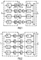
- Fig. 1 eine erste Ausführungsform und
- Fig. 2 eine zweite Ausführungsform der erfindungsgemäßen digitalen Analyse-Synthese-Filterbank
- Fig. 3 die in der ersten Ausführungsform nach Fig. 1 und
- Fig. 4 die in zweiten Ausführungsform nach Fig. 2 auftretenden Teilbandsignale im Frequenzbereich.
- Fig. 1 shows a first embodiment and
- Fig. 2 shows a second embodiment of the digital analysis-synthesis filter bank according to the invention
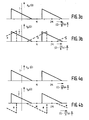
- Fig. 3 in the first embodiment of FIG. 1 and
- 4 shows the subband signals occurring in the second embodiment according to FIG. 2 in the frequency domain.
Die erfindungsgemäße digitale Analyse-Synthese-Filterbank kann in vorteilhafter Weise in den Teilbandcodern eine digitalen Funkübertragungssystems eingesetzt werden.The digital analysis-synthesis filter bank according to the invention can advantageously be used in the subband encoders of a digital radio transmission system.
Die Teilbandcodierung bekannter digitaler Funkübertragungssysteme basiert auf dem Prinzip der in Baumstruktur kaskadierten QMF-Filter (siehe "Multirate Digital Signal Processing" von Ronald E. Crochiere, Prentice-Hall). Der Vorteil dieses Verfahrens liegt -wie bereits ausgeführt-darin, daß die im Coder durch Unterabtastung entstehenden Rückfaltungsverzerrungen bei der Interpolationsfilterung im Decoder kompensiert werden.The subband coding of known digital radio transmission systems is based on the principle of QMF filters cascaded in a tree structure (see "Multirate Digital Signal Processing" by Ronald E. Crochiere, Prentice-Hall). The advantage of this method, as already stated, is that the refolding distortions which arise in the coder due to undersampling are compensated for in the interpolation filtering in the decoder.
Von Nachteil ist, daß -durch die Kaskadierungdie Laufzeit um ca. den Faktor 2 größer wird als aufgrund der Bandbreite erforderlich ist. Demgegenüber lassen sich mit sog. Polyphasen-Netzwerk-Filterbänken (PPN = Poly-Phase-Network), wie diese aus der DE-OS 31 18 473 bekannt sind, die Mindestlaufzeiten realisieren.The disadvantage is that the cascading increases the runtime by approximately a factor of 2 than is required due to the bandwidth. In contrast, so-called poly-phase network filter banks (PPN = poly-phase network), as are known from DE-OS 31 18 473, can achieve the minimum runtimes.
Die für Halbband-Filter bekannte QMF-Methode der Quadratur-Spiegel-Bedingung läßt sich auf die PPN-Filterbank übertragen. Unter Einbeziehung der realiserungsbedingten Verzögerungen besitzt damit die erfindungsgemäße digitale Analyse-Synthese- Filterbank mit M = 8 Kanälen eine Verzögerung von nur 10 ms. Hinzuzurechnen ist die zur Codierung und Decodierung der Teilsbandsignale benötigte Rechenzeit. Bei Verdoppelung der Kanalzahl ist dieser Wert ebenfalls zu verdoppeln. In dieser Hinsicht besitzt der Teilbandcoder mit der erfingungsgemäßen digitalen Ana-Teilbandcoder mit der' erfindungsgemäßen digitalen Analyse-Synthese-Filterbank einen deutlichen Vorteil gegenüber den verschiedenen RELP-Coder-Varianten.The QMF method of the quadrature mirror condition known for half-band filters can be transferred to the PPN filter bank. Including the delays due to the implementation, the digital analysis-synthesis filter bank according to the invention with M = 8 channels has a delay of only 10 ms. The computing time required for coding and decoding the subband signals must be added. If the number of channels is doubled, this value must also be doubled. In this regard, the subband encoder with the digital Ana subband encoder according to the invention with the digital analysis-synthesis filter bank according to the invention has a clear advantage over the various RELP coder variants.
Die adaptive Bitzuordnung auf die einzelnen Bänder erfolgt ähnlich dem aus der DE-OS 31 18 473 bekannten Verfahren. Dabei wird das erste Bit dem Kanal mit maximaler Leistung zugeordnet. Anschließend wird die Leistung dieses Kanals durch 4 dividiert und das nächste Bit wird wieder dem Kanal zugesprochen, der dann die größte Leistung besitzt. Dieses Verfahren wird solange wiederholt, bis alle Bits vergeben sind. Die eigentliche Bitzuordnung muß dem Decoder nicht mitgeteilt werden, da diese aus der übertragenen Nebeninformation bestimmt werden kann. Insgesamt werden für Coder und Decoder zusammen vier Prozessoren - (z.b. integrierter Signalprozessor NEC µ PD 7720) benötigt.The adaptive bit allocation to the individual bands is carried out similarly to the method known from DE-OS 31 18 473. The first bit is assigned to the channel with maximum power. The power of this channel is then divided by 4 and the next bit is assigned to the channel that has the highest power. This process is repeated until all bits have been assigned. The actual bit allocation does not have to be communicated to the decoder, since this can be determined from the secondary information transmitted. A total of four processors are required for encoders and decoders (e.g. integrated signal processor NEC µ PD 7720).
In Anbetracht der akustischen Randbedingungen für die Reduktion von Störungen werden zur Sprachcodierung nur solche Algorithmen eingesetzt, die weitgehend unempfindlich bei akustischen Hintergrundstörungen sind. Dies bedingt eine gewisse Transparenz bezüglich der Störungen, (d.h., daß Hintergrundstörungen mit übertragen werden). Es ist möglich, das gestörte Sprachsignal vor der Codierung durch adaptive Filterung zu verbessern. Ein Verfahren, das sich zur Reduktion bestimmter Störungen eignet ist aus der DE-OS 31 18 473 bekannt. Es basiert auf einer Teilbandzerlegung des gestörten Signals und einer adaptiven Verarbeitung der Teilbandsignale. Mit diesem Verfahren lassen sich insbesondere periodische Störungen wirkungsvoll unterdrücken, während bei rauschartigen Störungen ein reduziertes Restgeräusch verbleibt. In vorteilhafter Weise wird die daraus bekannte digitale Filteranordnung mit einem Teilbandcoder kombiniert. Für beide Funktionen ist dann nur eine gemeinsame Filterbank erforderlich.In view of the acoustic boundary conditions for the reduction of interference, only those algorithms are used for speech coding that are largely insensitive to acoustic background interference. This requires a certain transparency regarding the interference (i.e. that background interference is also transmitted). It is possible to improve the disturbed speech signal before coding by adaptive filtering. A method which is suitable for reducing certain disturbances is known from DE-OS 31 18 473. It is based on a subband breakdown of the disturbed signal and an adaptive processing of the subband signals. With this method, periodic disturbances in particular can be effectively suppressed, while reduced noise remains in the case of noise-like disturbances. The digital filter arrangement known therefrom is advantageously combined with a subband encoder. Only one common filter bank is then required for both functions.
Die Anaylse-Filterbank AF spaltet das zugeführte Eingangssignal x mittels parallel angeordneter, komplexer Bandpässe BP in komplexe Teilbandsignale auf, welche in einer nachfolgenden Einrichtung U unterabgetastet werden. Hierfür wird, wie in Fig. 1 dargestellt, bevorzugt eine Polyphasen-Netzwerk-Filterbank AF (PPN-Filterbank) mit einer Taktreduktion um den Faktor r = M/2 verwendet. Diese erste Stufe der Taktreduktion ist in der DE-OS 31 18 473 ausführlich beschrieben. Die M dabei auftretenden komplexen Teilbandsignale x)J. sind komplexwertig entsprechend der Gleichung
In der zweiten Stufe der Taktreduktion erfolgtmittels der Unterabtaster UA eine weitere Reduktion der Datenrate um den Faktor 2 gemäß der nachfolgenden Gleichung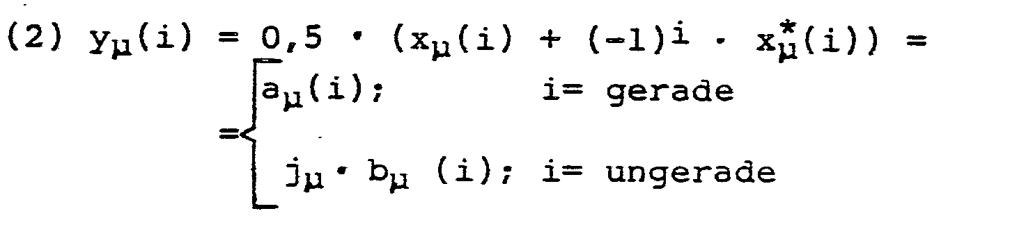
Da altemierend nur der Realteil oder der Imaginärteil benötigt wird, entspricht die Datenrate, für die Übertragung oder Speicherung und/oder Verarbeitung, der Datenrate bei maximaler Taktreduktion um den Faktor r=M.Since alternating only the real part or the imaginary part is required, the data rate for transmission or storage and / or processing corresponds to the data rate with maximum clock reduction by the factor r = M.
Die zweite Stufe der Taktreduktion um den Faktor 2 kann bei der Realisierung der Analyse-Filterbank AF unmittelbar berücksichtigt werden, indem der DFT-Prozessor derartig ausgelegt wird, daß er nur die jeweils benötigten Werte aµ (i) und bµ (i) berechnet.The second stage of the clock reduction by a factor of 2 can be taken into account immediately when implementing the analysis filter bank AF by designing the DFT processor in such a way that it only calculates the respectively required values a μ (i) and b μ (i) .
Wie in Fig. 1 dargestellt, wird am Eingang einer Synthese-Filterbank SF mittels einer Einrichtung I das Vorzeichen jedes zweiten Kanals invertiert, d.h. alle ungeradzahlig indizierten Kanäle. Zur Synthese wird auch eine PPN-Filterbank mit einer Interpolation um den Faktor r=M/2 verwendet. Auch hierbei wird in vorteilhafter Weise davon Gebrauch gemacht, daß zu jedem Zeitpunkt i die Teilbandsignale yµ (i) entweder nur reelle oder nur imaginäre Werte annehmen.As shown in FIG. 1, at the input of a synthesis filter bank SF, the sign of every second channel is inverted by means of a device I, that is to say all the odd-numbered channels. A PPN filter bank with an interpolation by the factor r = M / 2 is also used for the synthesis. Here, too, use is advantageously made that the subband signals y μ (i) assume only real or only imaginary values at any time i.
Aus "A Unified Approach to Digital Polyphase Filter Banks" von Dr. P. Vary and G. Wackersreuther, (Abdruck in AEÜ, Band 37, (1983), Seiten 29 bis 34) sind die Beziehungen zwischen den Frequenzspektren der Eingangs-und Ausgangssignale bekannt. Unter Berücksichtigung der vorgenannten zweistufigen Taktreduktion kann gezeigt werden, daß für das Ausgangssignal X folgende Gleichung gilt:
Bedingung hierfür ist, daß die Sperrgrenze des Prototyp-Tiefpasses der Filterbank, die in der nachfolgenden Gleichung angegebenen Bedingung erfüllt:
Anhand der in Fig. 3 dargestellten Teilbandsignale wird die zweite Stufe der erfindungsgemäßen Taktreduktion näher beschrieben und erläutert. Das in Fig. 3a dargestellte komplexe Teilbandsignal xµ (i) wird bei einer Unterabtastung gemäß der Gleichung (2) in das in Fig. 2b dargestellte Spektrum übergeführt. Dem konjugiert komplexen Zeitsignal x * (i) entspricht das gespiegelte, konjugiert komplexe Freqeunzspektrum, das durch Modulation mit (-1)(siehe Gleichung (2)) spektral um die normierte Frequenz w verschoben wird. Aufgrund der Spiegelung und Verschiebung kann durch alternierende Vorzeichenumkehr bei jedem zweiten Teilbandsignal eine Kompensation der störenden Rückfaltungsanteile bei der SyntheseFilterung vorgenommen werden. Indem durch die Spiegelung eine Wechselwirkung zwischen benachbarten Filtern der Analyse-und Synthese-Filterbank AF und SF entsteht, wird zwischen zwei benachbarten Kanälen ein Kompensationsmechanismus wirksam.The second stage of the clock reduction according to the invention is described and explained in more detail with reference to the subband signals shown in FIG. 3. The complex subband signal x μ (i) shown in FIG. 3a is converted into the spectrum shown in FIG. 2b during an undersampling according to equation (2). The conjugate complex time signal x * (i) corresponds to the mirrored, conjugate complex frequency spectrum, which is shifted spectrally by the normalized frequency w by modulation with (-1) (see equation (2)). Due to the mirroring and shifting, the interfering refolding components during synthesis filtering can be compensated for by alternating sign reversals for every second subband signal. Because the mirroring creates an interaction between adjacent filters of the analysis and synthesis filter banks AF and SF, a compensation mechanism becomes effective between two adjacent channels.
In Fig. 2 ist eine weitere Ausführungsform der erfindungsgemäßen digitalen Analyse-Sythese-Filterbank dargestellt. Für die Analyse-Filterbank AF wird ebenfalls (wie in Fig. 1) die PPN-Filterbank mit einer Taktreduktion um den Faktor r = M/2 verwendet. - Somit wird, wie bei der ersten Ausführungsform, für die erste Stufe der Taktreduktion die aus der DE-OS 31 18 473 bekannte Analyse-Filterbank benutzt. Für die weitere Taktreduktion in der zweiten Stufe werden die Teilbandsignale xµ benachbarter Kanäle komplementär um den Faktor 2 unterabgetastet, entsprechend der nachfolgenden Gleichung:
Um in Fig. 2 die Berechnung der Teilbandsignale yµ (i) gemäß der Gleichung (5a) zu verdeutlichen, ist der Unterabtaster mit einer Buchstaben A bezeichnet (Entsprechend für die Gleichung (5b) mit UB bezeichnet).In order to clarify the calculation of the subband signals y μ (i) according to equation (5a) in FIG. 2, the subsampler is designated with a letter A (correspondingly designated UB for equation (5b)).
Weiterhin wird die zur Unterabtastung gemäß der Gleichung (5a) komplementäre Unterabtastung der Teilbandsignale gemäß der Gleichung:
Im Vergleich zur Ausführungsform gemäß Fig. 1 ist vor der Synthese keine alternierende Vorzeichenumkehr benachbarter Teilbandsignale erforderlich. Unter den vorgenannten Voraussetzungen an den Prototype-Tiefpaß gilt in diesem Fall die Eingangs-Ausgangs-Beziehung der nachfolgenden Gleichung
Die in Gleichung (5b) angegebene Unterabtastung, welche zu den komplexen Teilbandsignalen yµ(i) führt, ist in Fig. 4 dargestellt . Wie ein Vergleich der Fig. 4b mit Fig. 2b zeigt, besitzt die durch die Unterabtastung entstehende gespiegelte Wiederholung des Spektrums ein negatives Vorzeichen (siehe auch Gleichung (5b) und Gleichung - (2)).The subsampling given in equation (5b), which leads to the complex subband signals y μ (i), is shown in FIG. 4. As a comparison of FIG. 4b with FIG. 2b shows, the mirrored repetition of the spectrum resulting from the undersampling has a negative sign (see also equation (5b) and equation - (2)).
Aufgrund dieser Vorzeichenumkehr kann die alternierende Vorzeichenumkehr der Teilbandsignale yµ (i) entfallen, wobei der wirksame Summenfrequenzgang nach Gleichung (6) entsteht.Because of this sign reversal, the alternating sign reversal of the subband signals y μ (i) can be omitted, the effective sum frequency response according to equation (6) being produced.
Claims (3)
Priority Applications (1)
| Application Number | Priority Date | Filing Date | Title |
|---|---|---|---|
| AT86200438T ATE86415T1 (en) | 1985-03-23 | 1986-03-19 | DIGITAL POLYPHASE FILTER BANK WITH MAXIMUM CLOCK REDUCTION. |
Applications Claiming Priority (2)
| Application Number | Priority Date | Filing Date | Title |
|---|---|---|---|
| DE19853510573 DE3510573A1 (en) | 1985-03-23 | 1985-03-23 | DIGITAL ANALYSIS SYNTHESIS FILTER BANK WITH MAXIMUM CYCLE REDUCTION |
| DE3510573 | 1985-03-23 |
Publications (3)
| Publication Number | Publication Date |
|---|---|
| EP0200239A2 true EP0200239A2 (en) | 1986-11-05 |
| EP0200239A3 EP0200239A3 (en) | 1989-01-11 |
| EP0200239B1 EP0200239B1 (en) | 1993-03-03 |
Family
ID=6266119
Family Applications (1)
| Application Number | Title | Priority Date | Filing Date |
|---|---|---|---|
| EP86200438A Expired - Lifetime EP0200239B1 (en) | 1985-03-23 | 1986-03-19 | Digital polyphase filter bank with maximum sampling-rate reduction |
Country Status (7)
| Country | Link |
|---|---|
| US (1) | US4766562A (en) |
| EP (1) | EP0200239B1 (en) |
| JP (1) | JPH0831775B2 (en) |
| AT (1) | ATE86415T1 (en) |
| AU (1) | AU5499286A (en) |
| CA (1) | CA1255361A (en) |
| DE (2) | DE3510573A1 (en) |
Cited By (4)
| Publication number | Priority date | Publication date | Assignee | Title |
|---|---|---|---|---|
| EP0370277A3 (en) * | 1988-11-24 | 1991-09-18 | Siemens Aktiengesellschaft | Sub-band transmission system |
| WO1993008651A1 (en) * | 1991-10-17 | 1993-04-29 | Fraunhofer-Gesellschaft zur Förderung der angewandten Forschung e.V. | Process for reducing frequency interlacing during acoustic or optical signal transmission and/or recording |
| CN102545833A (en) * | 2012-02-13 | 2012-07-04 | 西南民族大学 | Two-channel linear phase wavelet filter bank with two-level polyphase substructure |
| US8756266B2 (en) | 2005-09-16 | 2014-06-17 | Dolby International Ab | Partially complex modulated filter bank |
Families Citing this family (21)
| Publication number | Priority date | Publication date | Assignee | Title |
|---|---|---|---|---|
| FR2577084B1 (en) * | 1985-02-01 | 1987-03-20 | Trt Telecom Radio Electr | BENCH SYSTEM OF SIGNAL ANALYSIS AND SYNTHESIS FILTERS |
| DE3510573A1 (en) | 1985-03-23 | 1986-09-25 | Philips Patentverwaltung | DIGITAL ANALYSIS SYNTHESIS FILTER BANK WITH MAXIMUM CYCLE REDUCTION |
| DE3626862A1 (en) * | 1986-08-08 | 1988-02-11 | Philips Patentverwaltung | MULTI-STAGE TRANSMITTER ANTENNA COUPLING DEVICE |
| US5177700A (en) * | 1987-02-19 | 1993-01-05 | Ant Nachrichtentechnik Gmbh | Non-recursive half-band filter |
| WO1989004847A1 (en) * | 1987-11-20 | 1989-06-01 | Allied-Signal Inc. | Fluorinated copolymer and barrier films |
| FR2627647B1 (en) * | 1988-02-24 | 1995-04-14 | Alcatel Thomson Faisceaux | DIGITAL FILTER WITH INTEGRATED DECIMATION |
| JPH0770964B2 (en) * | 1988-06-10 | 1995-07-31 | 日本電気株式会社 | Chirp filter |
| US5068813A (en) * | 1989-11-07 | 1991-11-26 | Mts Systems Corporation | Phased digital filtering in multichannel environment |
| SE467680B (en) * | 1990-12-19 | 1992-08-24 | Johan Hellgren | DIGITAL FILTER BANK WITH Diminished Power Consumption |
| US5168214A (en) * | 1991-02-19 | 1992-12-01 | General Electric Company | Multi-rate superresolution time series spectrum analyzer |
| US6252909B1 (en) * | 1992-09-21 | 2001-06-26 | Aware, Inc. | Multi-carrier transmission system utilizing channels of different bandwidth |
| US5923273A (en) * | 1996-11-18 | 1999-07-13 | Crystal Semiconductor Corporation | Reduced power FIR filter |
| GB2344036B (en) * | 1998-11-23 | 2004-01-21 | Mitel Corp | Single-sided subband filters |
| US7058584B2 (en) * | 2002-01-28 | 2006-06-06 | Medco Health Solutions, Inc. | Apparatus and method for processing prescription requests using a remotely located prescription processing system |
| JP3735594B2 (en) * | 2002-06-28 | 2006-01-18 | 株式会社東芝 | Optical disk device and standby method of optical disk device |
| KR100723753B1 (en) * | 2002-08-01 | 2007-05-30 | 마츠시타 덴끼 산교 가부시키가이샤 | Audio decoding apparatus and audio decoding method based on spectral band replication |
| EP1543307B1 (en) * | 2002-09-19 | 2006-02-22 | Matsushita Electric Industrial Co., Ltd. | Audio decoding apparatus and method |
| US7917561B2 (en) | 2005-09-16 | 2011-03-29 | Coding Technologies Ab | Partially complex modulated filter bank |
| JP5034228B2 (en) * | 2005-11-30 | 2012-09-26 | 株式会社Jvcケンウッド | Interpolation device, sound reproduction device, interpolation method and interpolation program |
| US8718290B2 (en) | 2010-01-26 | 2014-05-06 | Audience, Inc. | Adaptive noise reduction using level cues |
| US9378754B1 (en) | 2010-04-28 | 2016-06-28 | Knowles Electronics, Llc | Adaptive spatial classifier for multi-microphone systems |
Family Cites Families (7)
| Publication number | Priority date | Publication date | Assignee | Title |
|---|---|---|---|---|
| DE3118473C2 (en) * | 1981-05-09 | 1987-02-05 | Felten & Guilleaume Fernmeldeanlagen GmbH, 8500 Nürnberg | Method for processing electrical signals with a digital filter arrangement |
| EP0070948B1 (en) * | 1981-07-28 | 1985-07-10 | International Business Machines Corporation | Voice coding method and arrangment for carrying out said method |
| DE3267481D1 (en) * | 1982-02-09 | 1986-01-02 | Ibm | Method for multi-speed digital transmission and apparatus for carrying out said method |
| US4691292A (en) * | 1983-04-13 | 1987-09-01 | Rca Corporation | System for digital multiband filtering |
| US4622680A (en) * | 1984-10-17 | 1986-11-11 | General Electric Company | Hybrid subband coder/decoder method and apparatus |
| FR2577084B1 (en) * | 1985-02-01 | 1987-03-20 | Trt Telecom Radio Electr | BENCH SYSTEM OF SIGNAL ANALYSIS AND SYNTHESIS FILTERS |
| DE3510573A1 (en) | 1985-03-23 | 1986-09-25 | Philips Patentverwaltung | DIGITAL ANALYSIS SYNTHESIS FILTER BANK WITH MAXIMUM CYCLE REDUCTION |
-
1985
- 1985-03-23 DE DE19853510573 patent/DE3510573A1/en not_active Withdrawn
-
1986
- 1986-03-19 DE DE8686200438T patent/DE3687852D1/en not_active Expired - Fee Related
- 1986-03-19 AT AT86200438T patent/ATE86415T1/en not_active IP Right Cessation
- 1986-03-19 EP EP86200438A patent/EP0200239B1/en not_active Expired - Lifetime
- 1986-03-20 CA CA000504575A patent/CA1255361A/en not_active Expired
- 1986-03-20 JP JP61061023A patent/JPH0831775B2/en not_active Expired - Lifetime
- 1986-03-21 AU AU54992/86A patent/AU5499286A/en not_active Abandoned
- 1986-03-24 US US06/843,331 patent/US4766562A/en not_active Expired - Fee Related
Cited By (5)
| Publication number | Priority date | Publication date | Assignee | Title |
|---|---|---|---|---|
| EP0370277A3 (en) * | 1988-11-24 | 1991-09-18 | Siemens Aktiengesellschaft | Sub-band transmission system |
| WO1993008651A1 (en) * | 1991-10-17 | 1993-04-29 | Fraunhofer-Gesellschaft zur Förderung der angewandten Forschung e.V. | Process for reducing frequency interlacing during acoustic or optical signal transmission and/or recording |
| AU660052B2 (en) * | 1991-10-17 | 1995-06-08 | Fraunhofer-Gesellschaft Zur Forderung Der Angewandten Forschung E.V. | Process for reducing frequency interlacing during acoustic or optical signal transmission and/or recording |
| US8756266B2 (en) | 2005-09-16 | 2014-06-17 | Dolby International Ab | Partially complex modulated filter bank |
| CN102545833A (en) * | 2012-02-13 | 2012-07-04 | 西南民族大学 | Two-channel linear phase wavelet filter bank with two-level polyphase substructure |
Also Published As
| Publication number | Publication date |
|---|---|
| US4766562A (en) | 1988-08-23 |
| AU5499286A (en) | 1986-09-25 |
| DE3687852D1 (en) | 1993-04-08 |
| JPS61220519A (en) | 1986-09-30 |
| ATE86415T1 (en) | 1993-03-15 |
| DE3510573A1 (en) | 1986-09-25 |
| EP0200239B1 (en) | 1993-03-03 |
| CA1255361A (en) | 1989-06-06 |
| JPH0831775B2 (en) | 1996-03-27 |
| EP0200239A3 (en) | 1989-01-11 |
Similar Documents
| Publication | Publication Date | Title |
|---|---|---|
| EP0200239B1 (en) | Digital polyphase filter bank with maximum sampling-rate reduction | |
| DE69216442T2 (en) | Device and method for processing digital signals | |
| EP0052847B1 (en) | Method and circuit for converting the sampling frequency of a series of samples avoiding conversion into a continuous signal | |
| DE69107841T2 (en) | TRANSFORMATION ENCODER AND DECODER WITH ADAPTIVE BLOCK LENGTH, ADAPTIVE TRANSFORMATION AND ADAPTIVE WINDOW FOR HIGH QUALITY SOUND SIGNALS. | |
| DE69221616T2 (en) | Digital filter bank with low computing complexity | |
| DE69521176T2 (en) | Method for decoding coded speech signals | |
| EP1741039B1 (en) | Information signal processing by carrying out modification in the spectral/modulation spectral region representation | |
| EP0065210A2 (en) | Electrical signal conditioning method with a digital filter device | |
| DE19706516C1 (en) | Encoding method for discrete signals and decoding of encoded discrete signals | |
| DE69817270T2 (en) | Arrangement for the generation of analog signals using analog-digital converters, especially for direct digital synthesis | |
| DE10234130B3 (en) | Device and method for generating a complex spectral representation of a discrete-time signal | |
| EP1016319B1 (en) | Process and device for coding a time-discrete stereo signal | |
| DE60118800T2 (en) | Unit filter bank for audio coding | |
| DE2811576C2 (en) | Transmission arrangement with conversion of discrete signals into a discrete single sideband frequency division multiplex signal and vice versa | |
| DE2707936C3 (en) | Single sideband frequency division multiplex transmission system | |
| EP0494990B1 (en) | Process for transmitting a signal | |
| DE60315960T2 (en) | METHOD AND DEVICE FOR ANALOG / DIGITAL IMPLEMENTATION | |
| EP0608281B1 (en) | Process for reducing frequency crosstalk during acoustic or optical signal transmission and/or recording | |
| DE69719260T2 (en) | Broadband spectral quantizer for speech | |
| EP0340301B1 (en) | Digital adaptive transform coding process | |
| DE3883414T2 (en) | Digital signal processing system with a filter bank. | |
| DE69803457T2 (en) | Audio Encoder | |
| DE3137679A1 (en) | ARRANGEMENT FOR TRANSMITTING LANGUAGE ACCORDING TO THE CHANNEL VOCODER PRINCIPLE | |
| DE69713971T2 (en) | ANALYSIS / SYNTHESIS FILTER SYSTEM WITH EFFICIENCY WITH ODD STACKED SINGLE-SIDED BAND FILTERBANK USING TDAC TECHNOLOGY | |
| EP0155008B1 (en) | Digital filter circuit for dividing signals into subbands |
Legal Events
| Date | Code | Title | Description |
|---|---|---|---|
| PUAI | Public reference made under article 153(3) epc to a published international application that has entered the european phase |
Free format text: ORIGINAL CODE: 0009012 |
|
| AK | Designated contracting states |
Kind code of ref document: A2 Designated state(s): AT BE CH DE FR GB IT LI NL SE |
|
| PUAB | Information related to the publication of an a document modified or deleted |
Free format text: ORIGINAL CODE: 0009199EPPU |
|
| RA1 | Application published (corrected) |
Date of ref document: 19861210 Kind code of ref document: A2 |
|
| RAP1 | Party data changed (applicant data changed or rights of an application transferred) |
Owner name: N.V. PHILIPS' GLOEILAMPENFABRIEKEN Owner name: PHILIPS PATENTVERWALTUNG GMBH |
|
| PUAL | Search report despatched |
Free format text: ORIGINAL CODE: 0009013 |
|
| AK | Designated contracting states |
Kind code of ref document: A3 Designated state(s): AT BE CH DE FR GB IT LI NL SE |
|
| 17P | Request for examination filed |
Effective date: 19890703 |
|
| 17Q | First examination report despatched |
Effective date: 19910731 |
|
| RTI1 | Title (correction) | ||
| GRAA | (expected) grant |
Free format text: ORIGINAL CODE: 0009210 |
|
| AK | Designated contracting states |
Kind code of ref document: B1 Designated state(s): AT BE CH DE FR GB IT LI NL SE |
|
| PG25 | Lapsed in a contracting state [announced via postgrant information from national office to epo] |
Ref country code: NL Effective date: 19930303 Ref country code: BE Effective date: 19930303 |
|
| REF | Corresponds to: |
Ref document number: 86415 Country of ref document: AT Date of ref document: 19930315 Kind code of ref document: T |
|
| PG25 | Lapsed in a contracting state [announced via postgrant information from national office to epo] |
Ref country code: AT Effective date: 19930319 |
|
| PG25 | Lapsed in a contracting state [announced via postgrant information from national office to epo] |
Ref country code: LI Effective date: 19930331 Ref country code: CH Effective date: 19930331 |
|
| REF | Corresponds to: |
Ref document number: 3687852 Country of ref document: DE Date of ref document: 19930408 |
|
| ITF | It: translation for a ep patent filed | ||
| GBT | Gb: translation of ep patent filed (gb section 77(6)(a)/1977) |
Effective date: 19930526 |
|
| ET | Fr: translation filed | ||
| NLV1 | Nl: lapsed or annulled due to failure to fulfill the requirements of art. 29p and 29m of the patents act | ||
| REG | Reference to a national code |
Ref country code: CH Ref legal event code: PL |
|
| PLBE | No opposition filed within time limit |
Free format text: ORIGINAL CODE: 0009261 |
|
| STAA | Information on the status of an ep patent application or granted ep patent |
Free format text: STATUS: NO OPPOSITION FILED WITHIN TIME LIMIT |
|
| 26N | No opposition filed | ||
| ITTA | It: last paid annual fee | ||
| EAL | Se: european patent in force in sweden |
Ref document number: 86200438.9 |
|
| ITPR | It: changes in ownership of a european patent |
Owner name: CAMBIO RAGIONE SOCIALE;PHILIPS ELECTRONICS N.V. |
|
| REG | Reference to a national code |
Ref country code: FR Ref legal event code: CD |
|
| PGFP | Annual fee paid to national office [announced via postgrant information from national office to epo] |
Ref country code: SE Payment date: 19970324 Year of fee payment: 12 |
|
| PG25 | Lapsed in a contracting state [announced via postgrant information from national office to epo] |
Ref country code: SE Free format text: LAPSE BECAUSE OF NON-PAYMENT OF DUE FEES Effective date: 19980320 |
|
| REG | Reference to a national code |
Ref country code: FR Ref legal event code: CD |
|
| EUG | Se: european patent has lapsed |
Ref document number: 86200438.9 |
|
| PGFP | Annual fee paid to national office [announced via postgrant information from national office to epo] |
Ref country code: FR Payment date: 20010326 Year of fee payment: 16 |
|
| PGFP | Annual fee paid to national office [announced via postgrant information from national office to epo] |
Ref country code: GB Payment date: 20010330 Year of fee payment: 16 |
|
| PGFP | Annual fee paid to national office [announced via postgrant information from national office to epo] |
Ref country code: DE Payment date: 20010516 Year of fee payment: 16 |
|
| REG | Reference to a national code |
Ref country code: GB Ref legal event code: IF02 |
|
| PG25 | Lapsed in a contracting state [announced via postgrant information from national office to epo] |
Ref country code: GB Free format text: LAPSE BECAUSE OF NON-PAYMENT OF DUE FEES Effective date: 20020319 |
|
| PG25 | Lapsed in a contracting state [announced via postgrant information from national office to epo] |
Ref country code: DE Free format text: LAPSE BECAUSE OF NON-PAYMENT OF DUE FEES Effective date: 20021001 |
|
| GBPC | Gb: european patent ceased through non-payment of renewal fee |
Effective date: 20020319 |
|
| PG25 | Lapsed in a contracting state [announced via postgrant information from national office to epo] |
Ref country code: FR Free format text: LAPSE BECAUSE OF NON-PAYMENT OF DUE FEES Effective date: 20021129 |
|
| REG | Reference to a national code |
Ref country code: FR Ref legal event code: ST |
|
| PG25 | Lapsed in a contracting state [announced via postgrant information from national office to epo] |
Ref country code: IT Free format text: LAPSE BECAUSE OF NON-PAYMENT OF DUE FEES;WARNING: LAPSES OF ITALIAN PATENTS WITH EFFECTIVE DATE BEFORE 2007 MAY HAVE OCCURRED AT ANY TIME BEFORE 2007. THE CORRECT EFFECTIVE DATE MAY BE DIFFERENT FROM THE ONE RECORDED. Effective date: 20050319 |