EP0200153A2 - Informationsspeichersystem - Google Patents
Informationsspeichersystem Download PDFInfo
- Publication number
- EP0200153A2 EP0200153A2 EP86105635A EP86105635A EP0200153A2 EP 0200153 A2 EP0200153 A2 EP 0200153A2 EP 86105635 A EP86105635 A EP 86105635A EP 86105635 A EP86105635 A EP 86105635A EP 0200153 A2 EP0200153 A2 EP 0200153A2
- Authority
- EP
- European Patent Office
- Prior art keywords
- information storage
- block
- key elements
- read
- key
- Prior art date
- Legal status (The legal status is an assumption and is not a legal conclusion. Google has not performed a legal analysis and makes no representation as to the accuracy of the status listed.)
- Withdrawn
Links
Images
Classifications
-
- G—PHYSICS
- G06—COMPUTING OR CALCULATING; COUNTING
- G06F—ELECTRIC DIGITAL DATA PROCESSING
- G06F16/00—Information retrieval; Database structures therefor; File system structures therefor
- G06F16/90—Details of database functions independent of the retrieved data types
- G06F16/901—Indexing; Data structures therefor; Storage structures
- G06F16/9017—Indexing; Data structures therefor; Storage structures using directory or table look-up
Definitions
- the present invention relates to an information storage method for storing in a memory pieces of information stored in an information storage part provided with identification codes in the opposite direction to that of the arrangement of key elements having the identification codes.
- An information storage system of this type serves to store pieces of name information of persons seating on reserved seats of for example a streetcar and a bus, etc., for each reserved seat number in an information storage part through keyed inputting operation, and read information on the names from the rear side of the reserved seats together with the numbers of the reserved seats, or to store information on proceeds, etc. in an account book at each date with keyed inputting operation, successively read them in the order of the date and store the read information in a memory. Furthermore, the information storage system is employed for stock control wherein pieces of information of articles arranged at prescribed positions are stored with key operation and read with the opposite procedures to storing ones.
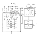
- an information storage part which part includes information storage areas 2, 3, 4, and 5 each having identification numbers 120, 130, 010, and 250 as identification codes K different in the order of arrangement thereof from each other.
- the information storage areas 2, 3, 4, and 5 are adapted to store desired informations A1 to A4 corresponding to the identification codes K.
- the identification numbers described above are selected as reserved seat numbers in a streetcar and a bus, etc., and the various informations A1 to A4 such as names of persons seating thereon corresponding to the reserved seat numbers.
- the identification number may be assumed to be dates, while the informations A1 to A4 to be proceeds corresponding to the dates.
- Such identification codes K and informations A1 to A4 are stored in the information storage part 1 as a memory means with use of a key input means and a display device.
- a data input device for input operation has already been known.
- Designated at 6 is an indexed part as a memory means in which key elements 9 to 12 including identification numbers 010, 120, 130, 250 as the identification codes K are arranged in a prescribed direction (left to right in the figure) after the information A1 to A4 are key-inputted in the information storage part 1. Also in this case, the key input means and the display (not shown) are employed to effect key input operation for the key elements. Thereupon, it is limited in view of read/write capability to subject in succession the key elements 9 to 12 to the key operation laterally. Consequently, the key elements 9 to 12 are divided into blocks 7, 8 for each prescribed number of the key elements and stored.
- Block decision areas are provided in the blocks 7, 8, which areas have rear stage block specifying parts 15, 16 for specifying in which block identification numbers next to last identification numbers 120, 250 of the respective blocks 7, 8 are existent.
- information for specifying the block 8 is stored in the rear stage block specifyng part 15 of the block 7, while information for specifying a rear stage block (not shown) behind the block 8 stored in the later stage block specifying part 16 of the block 8.
- the key elements 9, 10, 11, and 12 described above have length indication parts 19, 20, 21, and 22 for specifying the lengths of the key elements themselves required for finding positions of the next key elements in the blocks 7, 8. For example, retrieving the indication part 19 of the key element 9, the length of the key element 9 is found. Consequently, retrieving the key element 9 by a fraction corresponding to the length of the key element 9, head data of the next key element 10 can be found.
- the key elements 9, 10, 11, and 12 have position indication parts 23, 24, 25, and 26 for indicating at which addresses corresponding informations A1 to A4 are located in the information storage part 1. Prescribed information is entered in these length indication parts and the position indication parts in preparing the key elements 9 to 12. Furthermore, designated at 27 is a memory having a pluraity of information storage areas 28, 29, 30, and 31.
- Designated at 32 is a controller which stores in the memory 27 informations stored in the information storage part 1 in the order of arrangement of the identification numbers 010, 120, 130 and 250 based on instructions from the indexed part 6 described above.
- the controller 32 includes an element read means 32b operated based on an input from a fowardr read setting means 32a such as a switch, etc., for retrieving the blocks 7, 8 in the direction of the arrangement of the key elements, i.e., from the left to the right in the figure and for thereby reading the key elements 9 to 12 and delivering them to the memory 27, and a block indication means 32c for reading the rear stage block specifying parts 15, 16 after the element read means 32b finishes reading the key elements in each block, and for indicating to the element read means 32b which the rear stage block between respective blocks is.
- a fowardr read setting means 32a such as a switch, etc.
- the element reads means 32b after reading the respective key elements 9 to 12, detects, from the position indication parts 23 to 26, at which position in the information storage part 1 an identification number in the read key element is located, and reads the identification numbers, i.e., corresponding identification codes k and the informations A1 to A4 from the information storage part 1 for storing them in the memory. Consequently, once the element read means 32b reads all the key elements 9, 10 of the block 7, for example, the block specifying means 32c reads the information of the rear stage block specifying part 15. Since the block 8 has been specified in the rear stage block specifying part 15, the block specifying means 32c instructs the element read means 32b to retrieve the block 8, and thereby the element read means 32b retrieves the block 8 from the first key element 11. For the forward read setting means 32a, a switch interlocking with a specific key on a key board is available.
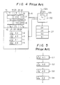
- the indexed part 6 is prepared while structured as shown in Fig. 4, upon preparing an indexed file. Such operation is effected with key operation while permitting an operator to observe a display.
- the key elements 9, 10, 11, and 12 are successively arranged in the increasing order of the identification numbers 010, 120, 130, and 250.
- informations are stored in the increasing order of the identification numbers 010, 120, or 130, 250, i.e., in the arrang- ment order of the key elements based on the indexed file so prepared, the read setting means 32a is therefor turned on.
- the forward read means 32b successively takes out the key elements 9, 10, involved in the front stage block 7 from the head thereof in the block 7, i.e., from the key element 9 toward the rear key element 10 and further takes out the last key element 10 in the block 7. Therefore, the block specifying means 32c decides the rear stage block 8 from the rear stage block specifying part 15 serving to specify the block number of the rear stage block present in the header 17 and instruct the element read means 32b to retrieve the block 8.
- the element read means 32b successibely takes out in repetition the key elements in the block 8 starting from the head in the block 8, i.e., the key 11 toward the rear element 12.
- the element read means 32b furthermore finds positions of corresponding informations A1 to A4, i.e., positions (addresses) in the information storage part 1 from the contents of the position indication parts 23, 24, 25, and 26 each time one of the key elements 9, 10, 11, and 12 is taken, and successively enters the informations A1 to A4 in the memory 27 together with the information codes.
- the informations are entered in the increasing order of the identification numbers 010, 120, 130, and 250.
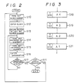
- the informations A1 to A4 can be entered in the order of steps S1, S2, S3, and S4 of Fig. 5.
- prior information storage systems as described above, are adpated to retrieve information in accordance with the order of arrangement of the key elements and to store the information in the increasing order to the identification numbers 010, 120, 130, and 250, but incapable of entering the identification numbers 010, 120, 130, and 250 in the decreasing order thereof.
- an object of the present invention to provide an information storage system capable of storing information in the opposite direction to the arrangement the key elements including the identification codes.
- An information storage system is adapted to read the key elements in the oppsosite direction to the order of arrangement of the identification codes and successively store information corresponding to the identification codes of the key elements in the memory.
- a controller stores informations corrsponding to the identification codes in the memory in the opposite direction to the order of arrangement of the key elements including the identification codes.
- designated at 33, 34 are front stage block specifying parts provided in the block decision areas 17, 18.
- the block specifying parts 33, 34 there set contents indicating in which blocks identification codes just before the identification codes 010 or 130 located at the fronts in the respective blocks 7, 8 are present.
- designated at 35 to 38 are indication parts for specifying the length of a key element needed to know the position of a front key element. Namely, when the element read means 32b retrieves and reads the respective blocks 7, 8 in a direction from the last key elements 10, 12 to the front elements 9, 11, positions of the key elements 9, 11 in front of the key elements 10, 12 can be decided with use of the contents of these indication parts 35 to 38.
- the front stage indication parts 33, 34 serving to specify the front stage block and the indication parts 35 to 38 are prepared upon making the indexed file.
- the controller 39 composed of the prior element read means 32b and the block specifying means 32c furthermore includes an element read means 32b adapted to be operatable based on an input from the backward read setting means 39a such as a switch to retrieve the blocks 7, 8 in the opposite direction to the arrangement of the key elements, i.e., from the right to the left in the figure, detect the identification codes k corresponding to the respective key elements 9 to 12 and the information A1 to A4 from the information storage part 1 for storing them in the memory 27, and a block specifying means 39c adapted to read, after allowing the element read means 39b to finish reading the key elements for each block, the front stage block specifying parts 33, 34 of the blocks 7, 8 and thereby indicating to the element read means 39b which a front stage block between the respective blocks is.
- the backward read setting means 39a such as a switch to retrieve the blocks 7, 8 in the opposite direction to the arrangement of the key elements, i.e., from the right to the left in the figure, detect the identification codes k
- the controller 39 serves to read the identification numbers 010, 120, 130, and 250 in the opposite order to the arrangement of the identification codes, i.e., in the order of the identification numbers 010, 120 or 130, 250, and read informations corresponding to the identification numbers 010, 120, 130, and 250 from the information storage part 1 in accordance with the above read order and store them in the memory 27.
- a step S10 represents processing just after initiating the operation, and also processing when the whole processing is finished based on decision in a Step S11.
- the block specifying means 39c takes out a block 8 having the rear key elements 11, 12 contained threin the block 8 having key elements with the largest identification numbers therein.
- the block 8 taken out in the step S10 is retrieved.
- the block 8 includes a plurality of key elements 11, 12 therein, in which they are arranged from the head to rear key elements in the increasing order of the identidication numbers 130, 250.
- the element read means 39b first takes out the last key element 12 in the block 8, and then takes out in repetition a front key element toward the head element.
- a position of a key element to be finally read out in the block 8 is evaluated. Since the lengths or the key elements 9 to 12 are not constant, a head position of the front key element 11 is evaluated by subtracting lengths of the front key element located just before the head positions of the key element 12 which has already been processed from the head position of the key element 12.
- a step S14 the position evaluated in the step S13 or the head position of the key element 12 already processed is subtracted from a position just before the above head position of the key element 12, i.e., the last position of the front key element 11 by the length of the front key element 11 whereby the head position of the key element 11 to be subsequently processed is evaluated.
- These evaluation is executed by an evaluation means additionally provided in the controller 39.
- a position indication part 37 included in the key element 11 taken out in the above step S14 is taken out in a step S 15, which information is entered into the memory 27 in a step S16.
- the operation is decided to be NO in a step S17 until information about the smallest identification number 130 in the block 8 has completely been entered, and the processing concerned is repeated in the above steps of S14, S15, and S16.
- the retrieving and reading processings are repeated initiating from the key element 12 arranged in the rear in the block 8, i.e., having the largest identification number to the key element arranged further ahead in the block 8, i.e., having a smaller identification number.
- the retrieving and reading operation on the interior of the block 8 is finished based on the decision in the step S17 but those on the whole blocks not finished based on the decision in the step S11, the operation is returned to the processing in the step S10.
- the front stage block indication part 34 located in the block header 18 shows upon the completion of the retrieving and reading operation about the block 8 in which block a key element having a smaller identificaion number next to the identification number 130 located in the block 8 is present.
- the block specifying means 39c takes out the contents of the front stage block specifying part 34 located in the header 18 of the block 8 which has already processed. It is in such a manner repeated in the blocks 7 and 8 to take out the key elements 9 to 12 from the rear in arrangement thereof and take out a block located in the front.
- informations can be entered in the decreasing order of the identification numbers of 010, 120, 130 and 250 after taking out the key element concerned.
- the information concenred can be entered in the order of the steps of S18, S19, S20, and S21 of Fig. 3. Furthermore, as described before, any information can be entered in the order shown in Fig. 5 when the forward/backward read setting means 32a is turned on.
- information in the indexed file can be entered in the opposite direction to the arrangement of the key elements, i.e., in the decreasing order of the identification numbers 010, 120, 130, and 250. Consequently, provided dates are provided as key values, they can advantageously stored successively from a new information on the dates.
- the information stored in the memory 27 is taken out by means of a printer or a display (not shown), and thereby the information can be captured with visual observation for decision.
- the key elements can be read out in the opposite order to the order of arrangement of the key elements including identification codes. And, in corfor- ming with the order of the key elements read out, informations corresponding to the identification codes involved in the key elements can be subsequently stored in the memory.
- the information strorge system according to the present invention can advantageously extend the coverage of applicability thereof.
Landscapes
- Engineering & Computer Science (AREA)
- Databases & Information Systems (AREA)
- Theoretical Computer Science (AREA)
- Software Systems (AREA)
- Data Mining & Analysis (AREA)
- Physics & Mathematics (AREA)
- General Engineering & Computer Science (AREA)
- General Physics & Mathematics (AREA)
- Information Retrieval, Db Structures And Fs Structures Therefor (AREA)
- Memory System (AREA)
Applications Claiming Priority (2)
| Application Number | Priority Date | Filing Date | Title |
|---|---|---|---|
| JP86965/85 | 1985-04-23 | ||
| JP60086965A JPS61245256A (ja) | 1985-04-23 | 1985-04-23 | 情報格納方式 |
Publications (2)
| Publication Number | Publication Date |
|---|---|
| EP0200153A2 true EP0200153A2 (de) | 1986-11-05 |
| EP0200153A3 EP0200153A3 (de) | 1991-07-03 |
Family
ID=13901583
Family Applications (1)
| Application Number | Title | Priority Date | Filing Date |
|---|---|---|---|
| EP19860105635 Withdrawn EP0200153A3 (de) | 1985-04-23 | 1986-04-23 | Informationsspeichersystem |
Country Status (3)
| Country | Link |
|---|---|
| US (1) | US4807122A (de) |
| EP (1) | EP0200153A3 (de) |
| JP (1) | JPS61245256A (de) |
Cited By (1)
| Publication number | Priority date | Publication date | Assignee | Title |
|---|---|---|---|---|
| CN104963562A (zh) * | 2012-08-17 | 2015-10-07 | 东隆五金工业股份有限公司 | 电子锁的传动机构 |
Families Citing this family (7)
| Publication number | Priority date | Publication date | Assignee | Title |
|---|---|---|---|---|
| JP2902402B2 (ja) * | 1987-09-30 | 1999-06-07 | 三菱電機株式会社 | データ処理装置 |
| JPH0766324B2 (ja) * | 1988-03-18 | 1995-07-19 | 三菱電機株式会社 | データ処理装置 |
| US5408655A (en) * | 1989-02-27 | 1995-04-18 | Apple Computer, Inc. | User interface system and method for traversing a database |
| US5339398A (en) * | 1989-07-31 | 1994-08-16 | North American Philips Corporation | Memory architecture and method of data organization optimized for hashing |
| US5604899A (en) * | 1990-05-21 | 1997-02-18 | Financial Systems Technology Pty. Ltd. | Data relationships processor with unlimited expansion capability |
| US5933839A (en) * | 1993-07-23 | 1999-08-03 | Kabushiki Kaisha Toshiba | Distributed file system for renewing data with high integrity |
| FR2716276B1 (fr) * | 1994-02-16 | 1996-05-03 | Sgs Thomson Microelectronics | Circuit de réorganisation de données. |
Family Cites Families (5)
| Publication number | Priority date | Publication date | Assignee | Title |
|---|---|---|---|---|
| US3701977A (en) * | 1969-10-27 | 1972-10-31 | Delaware Sds Inc | General purpose digital computer |
| US3942155A (en) * | 1973-12-03 | 1976-03-02 | International Business Machines Corporation | System for packing page frames with segments |
| JPS6019809B2 (ja) * | 1979-12-26 | 1985-05-18 | 株式会社日立製作所 | デ−タ処理装置 |
| US4611272A (en) * | 1983-02-03 | 1986-09-09 | International Business Machines Corporation | Key-accessed file organization |
| US4507752A (en) * | 1983-02-22 | 1985-03-26 | International Business Machines Corporation | In-place index compression |
-
1985
- 1985-04-23 JP JP60086965A patent/JPS61245256A/ja active Pending
-
1986
- 1986-04-23 EP EP19860105635 patent/EP0200153A3/de not_active Withdrawn
- 1986-04-23 US US06/856,070 patent/US4807122A/en not_active Expired - Fee Related
Cited By (1)
| Publication number | Priority date | Publication date | Assignee | Title |
|---|---|---|---|---|
| CN104963562A (zh) * | 2012-08-17 | 2015-10-07 | 东隆五金工业股份有限公司 | 电子锁的传动机构 |
Also Published As
| Publication number | Publication date |
|---|---|
| EP0200153A3 (de) | 1991-07-03 |
| JPS61245256A (ja) | 1986-10-31 |
| US4807122A (en) | 1989-02-21 |
Similar Documents
| Publication | Publication Date | Title |
|---|---|---|
| EP0200153A2 (de) | Informationsspeichersystem | |
| EP0220325B1 (de) | Herstellungsverfahren für ein programm zur bohrung von löchern | |
| US7322012B2 (en) | Display program, display method and display device | |
| EP0361989A3 (de) | Kartenschranksystem | |
| US5028923A (en) | ISO/EIA code converting method | |
| US6952811B1 (en) | Ladder circuit editing system | |
| EP0741348A2 (de) | Bestellungssteuergerät zum Vermindern der Eingabehandlungen mit einer Eingabeeinheit | |
| JP2002358316A (ja) | 画像処理装置及びその方法、プログラム | |
| JP2001015984A (ja) | 部品管理システム | |
| JP2522593B2 (ja) | 数値制御装置 | |
| JPS6055402B2 (ja) | 物品収納位置検索装置 | |
| JPH0744612A (ja) | 生産情報出力装置 | |
| JPH0122106B2 (de) | ||
| JPS60175151A (ja) | 情報処理装置 | |
| US5978321A (en) | Retrieval method with repeated retrieval of inputted characters and medium storing implementing software | |
| JPH0652559B2 (ja) | 駐車場の管理方法 | |
| JP2555764B2 (ja) | 多品種少量生産システムにおける工作物の加工方法 | |
| EP0351786A2 (de) | Datenverarbeitungsgerät | |
| JPH0317613B2 (de) | ||
| JPH0224789A (ja) | 自動販売機のデータ設定装置 | |
| JP3434866B2 (ja) | 自動製品配列装置 | |
| JP2899763B2 (ja) | 加工治具ファイル作成装置 | |
| JPH0490089A (ja) | カードを使用した管理装置 | |
| US5754880A (en) | Method for component mounting based on numerical control data generating from component information corresponding to supply numbers associated with factory numbers listed in CAD data | |
| JP2684965B2 (ja) | マイクロプログラムのパッチ支援装置 |
Legal Events
| Date | Code | Title | Description |
|---|---|---|---|
| PUAI | Public reference made under article 153(3) epc to a published international application that has entered the european phase |
Free format text: ORIGINAL CODE: 0009012 |
|
| AK | Designated contracting states |
Kind code of ref document: A2 Designated state(s): DE FR GB |
|
| PUAB | Information related to the publication of an a document modified or deleted |
Free format text: ORIGINAL CODE: 0009199EPPU |
|
| RA1 | Application published (corrected) |
Date of ref document: 19861210 Kind code of ref document: A2 |
|
| 17P | Request for examination filed |
Effective date: 19901228 |
|
| PUAL | Search report despatched |
Free format text: ORIGINAL CODE: 0009013 |
|
| AK | Designated contracting states |
Kind code of ref document: A3 Designated state(s): DE FR GB |
|
| 17Q | First examination report despatched |
Effective date: 19911211 |
|
| STAA | Information on the status of an ep patent application or granted ep patent |
Free format text: STATUS: THE APPLICATION IS DEEMED TO BE WITHDRAWN |
|
| 18D | Application deemed to be withdrawn |
Effective date: 19930220 |
|
| RIN1 | Information on inventor provided before grant (corrected) |
Inventor name: KAZUYUKI, BABA |