EP0198449A1 - Verfahren zur Herstellung von Verteilerkappen für Zündstromverteiler - Google Patents
Verfahren zur Herstellung von Verteilerkappen für Zündstromverteiler Download PDFInfo
- Publication number
- EP0198449A1 EP0198449A1 EP86105020A EP86105020A EP0198449A1 EP 0198449 A1 EP0198449 A1 EP 0198449A1 EP 86105020 A EP86105020 A EP 86105020A EP 86105020 A EP86105020 A EP 86105020A EP 0198449 A1 EP0198449 A1 EP 0198449A1
- Authority
- EP
- European Patent Office
- Prior art keywords
- electrodes
- electrode
- section
- widening
- shaped
- Prior art date
- Legal status (The legal status is an assumption and is not a legal conclusion. Google has not performed a legal analysis and makes no representation as to the accuracy of the status listed.)
- Withdrawn
Links
- 238000004519 manufacturing process Methods 0.000 title claims abstract description 12
- 238000000034 method Methods 0.000 claims abstract description 17
- 238000001746 injection moulding Methods 0.000 claims abstract description 9
- 238000001721 transfer moulding Methods 0.000 claims abstract description 8
- 239000007924 injection Substances 0.000 claims abstract description 6
- 239000004033 plastic Substances 0.000 claims description 8
- 230000007704 transition Effects 0.000 claims description 3
- OKTJSMMVPCPJKN-UHFFFAOYSA-N Carbon Chemical compound [C] OKTJSMMVPCPJKN-UHFFFAOYSA-N 0.000 claims description 2
- 229910052799 carbon Inorganic materials 0.000 claims description 2
- 229920001169 thermoplastic Polymers 0.000 claims description 2
- 239000004416 thermosoftening plastic Substances 0.000 claims description 2
- 238000013461 design Methods 0.000 abstract description 2
- 238000005516 engineering process Methods 0.000 abstract 1
- 230000035515 penetration Effects 0.000 abstract 1
- 230000000630 rising effect Effects 0.000 description 2
- 229920001187 thermosetting polymer Polymers 0.000 description 2
- 238000012546 transfer Methods 0.000 description 2
- 230000006978 adaptation Effects 0.000 description 1
- 230000006378 damage Effects 0.000 description 1
- 239000000463 material Substances 0.000 description 1
- 239000002184 metal Substances 0.000 description 1
- 238000012986 modification Methods 0.000 description 1
- 230000004048 modification Effects 0.000 description 1
- 230000000149 penetrating effect Effects 0.000 description 1
- 238000012805 post-processing Methods 0.000 description 1
- 238000012545 processing Methods 0.000 description 1
- 230000002035 prolonged effect Effects 0.000 description 1
- 238000007789 sealing Methods 0.000 description 1
- 229920005992 thermoplastic resin Polymers 0.000 description 1
Images


Classifications
-
- H—ELECTRICITY
- H01—ELECTRIC ELEMENTS
- H01R—ELECTRICALLY-CONDUCTIVE CONNECTIONS; STRUCTURAL ASSOCIATIONS OF A PLURALITY OF MUTUALLY-INSULATED ELECTRICAL CONNECTING ELEMENTS; COUPLING DEVICES; CURRENT COLLECTORS
- H01R39/00—Rotary current collectors, distributors or interrupters
- H01R39/60—Devices for interrupted current collection, e.g. commutating device, distributor, interrupter
-
- F—MECHANICAL ENGINEERING; LIGHTING; HEATING; WEAPONS; BLASTING
- F02—COMBUSTION ENGINES; HOT-GAS OR COMBUSTION-PRODUCT ENGINE PLANTS
- F02P—IGNITION, OTHER THAN COMPRESSION IGNITION, FOR INTERNAL-COMBUSTION ENGINES; TESTING OF IGNITION TIMING IN COMPRESSION-IGNITION ENGINES
- F02P7/00—Arrangements of distributors, circuit-makers or -breakers, e.g. of distributor and circuit-breaker combinations or pick-up devices
- F02P7/02—Arrangements of distributors, circuit-makers or -breakers, e.g. of distributor and circuit-breaker combinations or pick-up devices of distributors
- F02P7/021—Mechanical distributors
- F02P7/022—Details of the distributor rotor or electrode
Definitions
- the invention relates to a method for producing distributor caps for ignition current distributors in Otto engines.
- Such distributor caps have an electrode for transferring the ignition current supplied by the current source - usually by switching on a high-voltage ignition coil - and - depending on the number of spark plugs to be supplied with current - two or more fixed electrodes for taking over the ignition current delivered by the distributor rotor and forwarding it to the spark plugs the motor via power cables connected to the electrodes on the outside of the distributor cap.
- electrodes are used according to the prior art where the protruding inwardly into the distributor caps E lektrodenzapfen in the region of passage through the distributor cap - seen cut-inverted - rectangular or widened at an obtuse angle to a cylindrical cable connector, wherein the power cable is plugged in depending on the manufacturer in the sleeve-shaped cable connection or pin shaped on the Cable connection is pushed on.
- the electrodes they are inserted into the distributor cap in a first step in the manufacture of the distributor cap without first making the contact with the sliding track on the electrode pin during the injection molding or injection molding process, by using the usual thermosetting or thermoplastic resin on the injection molding or transfer molding Surrounding inside and outside of the distributor cap.
- the grinding tracks of the electrodes must be turned out or milled out in a separate subsequent working step on processing machines and at the same time the plastic adhering to the electrode pins must be removed.
- the electrode for the power supply to the distributor must be freed from the plastic surrounding it on the inside in order to enable the spring-loaded carbon pins to be inserted.
- the object of the invention is to further develop the method for producing distributor caps so that they can be produced in one work step with prefabricated electrodes which have the contact surfaces and sliding track contacts.
- the method according to the invention offers the following advantages over the known methods: by using electrodes that have a multi-stage widening at the transition from the electrode pin to the cable connections, be it obtuse-angled, right-angled, convex or concave or in combination of such stages, a perfect seal is achieved reached in the area of the passage of the electrode through the distributor cap jacket and thus prevents leakage currents and / or the entry of moisture.
- the design of the electrodes according to the invention prevents the plastic from rising on the electrode pins during the injection or transfer molding process, as in the conventional production processes. Therefore, the electrodes can be given their final shape, in particular sliding track contacts, before the distributor cap is manufactured. In addition, the electrodes are not surrounded with plastic after the injection or transfer molding process due to the avoided rising of the plastic in the mechanical form, but rather pure metal and thus fully electrically conductive.
- the jacket 2 of the distributor cap 1 is produced in a manner known per se from plastic, in particular from thermoplastic or thermosetting plastic, in the injection or transfer molding process, and the current output electrodes 3, 3 ', 3' are applied during the transfer or transfer molding process. ' such as the electrode 4, 4 'is cast or injected into the jacket 2 for current consumption.
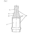
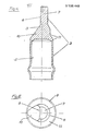
- the electrodes 3, 3 ', 31 and 4, 4' used for this purpose have the sleeve-shaped recesses 5 according to FIGS. 1, 3, 4, 10 and 11 at their outlet from the distributor cap 1 or from their jacket 2 for inserting the connecting cable or the pin-shaped connecting pins 6 for plugging in the connecting cables according to FIGS. 6-8.
- the electrodes 3, 3 'used in the manufacturing method according to the invention furthermore have the electrode pins 7 with the sliding track contacts 8 attached before the manufacturing of the distributor cap 1, against which the distributor rotor passes as it rotates.
- the electrode pin widens in the area of the passage of the electrode through the cap jacket 2 in a first section 9 in the shape of a truncated cone (trapezoidal in longitudinal section). This section merges into a further section 10, which continues the obtuse angle of section 9 of the sliding path contact 8, but otherwise runs parallel to the longitudinal axis of the electrode. From section 10 the electrode widens concave / convex in section 11 to sleeve 5. In sections 10 and -11 the electrode has a round cross section.
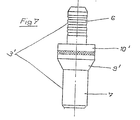
- the electrode peg 7 merges into the section 9', which is designed like the section 9 described, but projects laterally more strongly than in the latter.
- Section 9 'adjoins section 10' which is piston-shaped and the outside of which extends over the entire circumference parallel to the longitudinal axis of the electrode.
- This section 10 ' jumps at the outlet of the electrode 3' from the jacket 2 of the Distributor cap 1 in its entire radius and passes into the connecting pin 6.
- the electrodes used for the described method can also, as shown in FIGS. 10 and 11, in a further modification 3 ′′ have an electrode stud 7 ′ that is rectangular or square in cross section and that merges into a section 9 ′′ that is also rectangular or square in cross section .
- Section 9 ′′ adjoins section 10 ′′, which in turn widens concavely / convexly in section 11 ′′ to sleeve 5, section 11 ′′ and sleeve 5 again having a circular cross section.
- electrodes can also be used in which the step-like widening from the electrode pins 7 is held at different angles, radii or combinations than those shown in FIGS. 1-11.
- the use of electrodes with an initially rectangular and then an obtuse-angled widening or also with only convex / concave widened sections falls under the invention.
Landscapes
- Engineering & Computer Science (AREA)
- Chemical & Material Sciences (AREA)
- Combustion & Propulsion (AREA)
- Mechanical Engineering (AREA)
- General Engineering & Computer Science (AREA)
- Ignition Installations For Internal Combustion Engines (AREA)
Applications Claiming Priority (2)
| Application Number | Priority Date | Filing Date | Title |
|---|---|---|---|
| DE3513283 | 1985-04-13 | ||
| DE19853513283 DE3513283A1 (de) | 1985-04-13 | 1985-04-13 | Verfahren zur herstellung von verteilerkappen fuer zuendstromverteiler |
Publications (1)
| Publication Number | Publication Date |
|---|---|
| EP0198449A1 true EP0198449A1 (de) | 1986-10-22 |
Family
ID=6267932
Family Applications (1)
| Application Number | Title | Priority Date | Filing Date |
|---|---|---|---|
| EP86105020A Withdrawn EP0198449A1 (de) | 1985-04-13 | 1986-04-11 | Verfahren zur Herstellung von Verteilerkappen für Zündstromverteiler |
Country Status (4)
| Country | Link |
|---|---|
| EP (1) | EP0198449A1 (enExample) |
| JP (1) | JPS62502905A (enExample) |
| DE (1) | DE3513283A1 (enExample) |
| WO (1) | WO1986006219A1 (enExample) |
Cited By (1)
| Publication number | Priority date | Publication date | Assignee | Title |
|---|---|---|---|---|
| EP0432741A1 (de) * | 1989-12-14 | 1991-06-19 | DODUCO GMBH + Co Dr. Eugen DÀ¼rrwächter | Zündverteiler für Verbrennungskraftmaschinen |
Citations (8)
| Publication number | Priority date | Publication date | Assignee | Title |
|---|---|---|---|---|
| US1984275A (en) * | 1933-05-18 | 1934-12-11 | Maliory Res Company | Distributor |
| US3001035A (en) * | 1958-10-21 | 1961-09-19 | Anderson W Butts | Distributor cap |
| US3766339A (en) * | 1972-05-08 | 1973-10-16 | E Melidosian | Circuit interruptor for ignition system with improved rotary contact |
| FR2250387A5 (enExample) * | 1973-11-07 | 1975-05-30 | Ducellier & Cie | |
| FR2324136A1 (fr) * | 1975-09-10 | 1977-04-08 | Bosch Gmbh Robert | Organe de jonction pour les dispositifs d'allumage de moteurs a combustion interne |
| GB2047470A (en) * | 1979-04-03 | 1980-11-26 | Mitsubishi Electric Corp | Ventilator of distributor for engine ignition system |
| DE3329647A1 (de) * | 1983-08-17 | 1985-02-28 | Robert Bosch Gmbh, 7000 Stuttgart | Zum abdecken eines zuendverteilers dienende isolierstoffkappe |
| US4544812A (en) * | 1984-09-17 | 1985-10-01 | General Motors Corporation | Ignition distributor cap |
Family Cites Families (2)
| Publication number | Priority date | Publication date | Assignee | Title |
|---|---|---|---|---|
| DE7102894U (de) * | 1971-04-29 | Bremicker E Kg | Zundverteüerkappe fur Brennkraft maschinen | |
| GB1192070A (en) * | 1967-10-17 | 1970-05-20 | Amp Inc | High Voltage Electrical Connector |
-
1985
- 1985-04-13 DE DE19853513283 patent/DE3513283A1/de active Granted
-
1986
- 1986-04-11 JP JP61502215A patent/JPS62502905A/ja active Pending
- 1986-04-11 EP EP86105020A patent/EP0198449A1/de not_active Withdrawn
- 1986-04-11 WO PCT/DE1986/000160 patent/WO1986006219A1/de not_active Ceased
Patent Citations (8)
| Publication number | Priority date | Publication date | Assignee | Title |
|---|---|---|---|---|
| US1984275A (en) * | 1933-05-18 | 1934-12-11 | Maliory Res Company | Distributor |
| US3001035A (en) * | 1958-10-21 | 1961-09-19 | Anderson W Butts | Distributor cap |
| US3766339A (en) * | 1972-05-08 | 1973-10-16 | E Melidosian | Circuit interruptor for ignition system with improved rotary contact |
| FR2250387A5 (enExample) * | 1973-11-07 | 1975-05-30 | Ducellier & Cie | |
| FR2324136A1 (fr) * | 1975-09-10 | 1977-04-08 | Bosch Gmbh Robert | Organe de jonction pour les dispositifs d'allumage de moteurs a combustion interne |
| GB2047470A (en) * | 1979-04-03 | 1980-11-26 | Mitsubishi Electric Corp | Ventilator of distributor for engine ignition system |
| DE3329647A1 (de) * | 1983-08-17 | 1985-02-28 | Robert Bosch Gmbh, 7000 Stuttgart | Zum abdecken eines zuendverteilers dienende isolierstoffkappe |
| US4544812A (en) * | 1984-09-17 | 1985-10-01 | General Motors Corporation | Ignition distributor cap |
Cited By (1)
| Publication number | Priority date | Publication date | Assignee | Title |
|---|---|---|---|---|
| EP0432741A1 (de) * | 1989-12-14 | 1991-06-19 | DODUCO GMBH + Co Dr. Eugen DÀ¼rrwächter | Zündverteiler für Verbrennungskraftmaschinen |
Also Published As
| Publication number | Publication date |
|---|---|
| DE3513283A1 (de) | 1986-10-16 |
| DE3513283C2 (enExample) | 1988-12-08 |
| WO1986006219A1 (fr) | 1986-10-23 |
| JPS62502905A (ja) | 1987-11-19 |
Similar Documents
| Publication | Publication Date | Title |
|---|---|---|
| EP0233319A2 (de) | Koaxialer Winkelstecker | |
| DE69516241T2 (de) | Teil einer Zündung für innere Brennkraftmaschinen und Verfahren zu seiner Herstellung | |
| DE10261434A1 (de) | Isolierter Statorkern mit Befestigungsmerkmalen | |
| EP0513597B1 (de) | Verfahren zur Herstellung einer Steuerleiste | |
| EP2396857A1 (de) | Vorrichtung zur befestigung eines bolzens in einer polklemme | |
| WO2020007555A1 (de) | Steckverbindungselement für ein kraftfahrzeug und verfahren zum herstellen eines solchen steckverbindungselements | |
| DE19526313C2 (de) | Diodenfassung für LED mit Steckverbindung und Vorwiderstand und Verfahren zu deren Herstellung | |
| DE2701291A1 (de) | Verfahren zur herstellung des koerperendes einer elektromagnetischen einspritzduese sowie elektromagnetische einspritzduese | |
| EP0187902A1 (de) | Gehäuse für ein elektrisches Bauteil | |
| EP0198449A1 (de) | Verfahren zur Herstellung von Verteilerkappen für Zündstromverteiler | |
| DE4135679A1 (de) | Stecker fuer elektrische verbindungen | |
| EP0354582A2 (de) | Mehrpolige Steckvorrichtung, insbesondere einer aus einem Gerätestecker und/oder einer Geräte-Steckdose bestehenden mehrpoligen Geräte-Steckvorrichtung für Elektro-Flurförderzeuge, Batterien oder Ladegeräte, sowie Steckverbindersatz daraus, mit Spannungscodierung und zumindest einer weiteren Codierung, insbesondere für Trocken- und/oder Nassbatterien | |
| DE1638203A1 (de) | Stromwender | |
| DE3913026C2 (enExample) | ||
| EP3503307A1 (de) | Elektrisches kupplungsteil und dichtelement | |
| DE10122816B4 (de) | Stecker einer Steckverbindung | |
| WO1986004459A1 (fr) | Commutateur pour machines electriques | |
| DE3510369C2 (enExample) | ||
| DE102004060179B4 (de) | Einspritzventil mit einem verbesserten Anschluss eines Anschlusssteckers | |
| EP0700586B1 (de) | Elektrisches gerät mit vorrichtung zum elektrischen anschluss zweier elektrischer anschlussleiter an das gerät | |
| EP1468858A1 (de) | Tankverschluss | |
| WO2000026550A1 (de) | Lagerschale und kugelgelenk mit einer solchen lagerschale | |
| DE9217862U1 (de) | Kabelendstecker für Koaxialkabel | |
| DE8604142U1 (de) | Koaxialer Winkelstecker | |
| DE2118577A1 (de) | Isolierte elektrische Buchse |
Legal Events
| Date | Code | Title | Description |
|---|---|---|---|
| PUAI | Public reference made under article 153(3) epc to a published international application that has entered the european phase |
Free format text: ORIGINAL CODE: 0009012 |
|
| AK | Designated contracting states |
Kind code of ref document: A1 Designated state(s): FR GB IT |
|
| 17P | Request for examination filed |
Effective date: 19870416 |
|
| 17Q | First examination report despatched |
Effective date: 19880525 |
|
| STAA | Information on the status of an ep patent application or granted ep patent |
Free format text: STATUS: THE APPLICATION IS DEEMED TO BE WITHDRAWN |
|
| 18D | Application deemed to be withdrawn |
Effective date: 19881005 |