EP1468858A1 - Tankverschluss - Google Patents
Tankverschluss Download PDFInfo
- Publication number
- EP1468858A1 EP1468858A1 EP04008551A EP04008551A EP1468858A1 EP 1468858 A1 EP1468858 A1 EP 1468858A1 EP 04008551 A EP04008551 A EP 04008551A EP 04008551 A EP04008551 A EP 04008551A EP 1468858 A1 EP1468858 A1 EP 1468858A1
- Authority
- EP
- European Patent Office
- Prior art keywords
- contact
- tank
- tank cap
- handle part
- cap according
- Prior art date
- Legal status (The legal status is an assumption and is not a legal conclusion. Google has not performed a legal analysis and makes no representation as to the accuracy of the status listed.)
- Withdrawn
Links
Images

Classifications
-
- F—MECHANICAL ENGINEERING; LIGHTING; HEATING; WEAPONS; BLASTING
- F16—ENGINEERING ELEMENTS AND UNITS; GENERAL MEASURES FOR PRODUCING AND MAINTAINING EFFECTIVE FUNCTIONING OF MACHINES OR INSTALLATIONS; THERMAL INSULATION IN GENERAL
- F16L—PIPES; JOINTS OR FITTINGS FOR PIPES; SUPPORTS FOR PIPES, CABLES OR PROTECTIVE TUBING; MEANS FOR THERMAL INSULATION IN GENERAL
- F16L55/00—Devices or appurtenances for use in, or in connection with, pipes or pipe systems
- F16L55/10—Means for stopping flow from or in pipes or hoses
- F16L55/11—Plugs
- F16L55/1108—Plugs fixed by screwing or by means of a screw-threaded ring
-
- B—PERFORMING OPERATIONS; TRANSPORTING
- B60—VEHICLES IN GENERAL
- B60K—ARRANGEMENT OR MOUNTING OF PROPULSION UNITS OR OF TRANSMISSIONS IN VEHICLES; ARRANGEMENT OR MOUNTING OF PLURAL DIVERSE PRIME-MOVERS IN VEHICLES; AUXILIARY DRIVES FOR VEHICLES; INSTRUMENTATION OR DASHBOARDS FOR VEHICLES; ARRANGEMENTS IN CONNECTION WITH COOLING, AIR INTAKE, GAS EXHAUST OR FUEL SUPPLY OF PROPULSION UNITS IN VEHICLES
- B60K15/00—Arrangement in connection with fuel supply of combustion engines or other fuel consuming energy converters, e.g. fuel cells; Mounting or construction of fuel tanks
- B60K15/03—Fuel tanks
- B60K15/04—Tank inlets
- B60K15/0406—Filler caps for fuel tanks
-
- B—PERFORMING OPERATIONS; TRANSPORTING
- B60—VEHICLES IN GENERAL
- B60K—ARRANGEMENT OR MOUNTING OF PROPULSION UNITS OR OF TRANSMISSIONS IN VEHICLES; ARRANGEMENT OR MOUNTING OF PLURAL DIVERSE PRIME-MOVERS IN VEHICLES; AUXILIARY DRIVES FOR VEHICLES; INSTRUMENTATION OR DASHBOARDS FOR VEHICLES; ARRANGEMENTS IN CONNECTION WITH COOLING, AIR INTAKE, GAS EXHAUST OR FUEL SUPPLY OF PROPULSION UNITS IN VEHICLES
- B60K15/00—Arrangement in connection with fuel supply of combustion engines or other fuel consuming energy converters, e.g. fuel cells; Mounting or construction of fuel tanks
- B60K15/03—Fuel tanks
- B60K2015/03328—Arrangements or special measures related to fuel tanks or fuel handling
- B60K2015/03401—Arrangements or special measures related to fuel tanks or fuel handling for preventing electrostatic charges
Definitions
- the invention relates to a tank cap consisting of a tank cap and an electrically conductive tank neck, the fuel cap for handling it Has grip part made of electrically conductive material, electrical contact with at least one resilient Contact protrusion has the screwed on the filler neck to discharge static electricity is applied.
- a fuel cap is not electrically conductive and also has no electrical connection to the tank neck, there is the problem that the fuel cap is electrical can charge when handled by someone which is charged with static electricity, for example due to friction on plastic seats when getting out. This can lead to sparking and thus to a Deflagration of the fuel vapor flowing out of the tank neck when removing the fuel cap.
- the handle part of the tank cap from an electric to produce conductive material, for example made of a plastic mixed with carbon (graphite) like polyamide, and electrical contact between Handle part and filler neck if the Tank cap is screwed onto the nozzle.
- conductive material for example made of a plastic mixed with carbon (graphite) like polyamide
- the invention has for its object a tank cap of the type mentioned in such a way that a as far as possible equipotential bonding between the tank cap and fuel nozzle and thus the risk of Spark formation is reduced to a minimum.
- the contact projection or the contact projections preferably molded on the inside of the handle or is or are cast.
- the molding can be done by casting on, especially injection molding, to the handle part, especially when the contact protrusion and grip part consist of electrically conductive plastic.
- the basic idea of the invention is therefore for the electrical Contact between the handle and the fuel nozzle is not one separate transmission ring with contact protrusions to provide, but the contact projections directly on the To attach the handle part, by molding or pouring, so that an intimate connection between contact protrusion and handle part while avoiding a contact resistance is produced. It has been shown that this a much better and faster equipotential bonding achieved between the grip part and the tank neck and so that the security against sparking is increased. Moreover is the manufacture of the tank cap according to the invention much easier and less material, so that the manufacturing costs are significantly reduced.
- the Contact projection or the contact projections like leaf springs is or are formed and radially obliquely inwards protrudes or protrudes.
- the shape of the tank neck can be achieved be that the respective contact lead under sufficient Bias is applied to the tank neck and accordingly the contact resistance is low.
- the contact projection or the Contact protrusions starting in a circumferential direction radially obliquely on the inside of the handle part protrude inside like a ramp. In this way high investment forces can be realized without thereby screwing or unscrewing the tank cap is essential is difficult.
- the inside of the handle part in the area of the contact projection or the contact projections such recesses has that the respective contact projection when moving fits radially outwards into the recess.
- Contact protrusions have a large spring travel available for what their adaptability to the shape of the tank neck favored.
- the contact protrusion or the contact protrusions should be on one edge of the recess be molded on.
- the present invention is not limited to what the Number of contact protrusions. Has been useful there are two contact projections, that are diametrically opposed. This does not exclude from that only a contact projection is provided or but also more than two.
- the tank cap 1 shown in Figure 1 consists of the upper end of a tank neck 2 made of metal and one screwed-in fuel cap 3.
- the fuel cap has an engagement part 4, which has a thread 5 on the outside, that into a corresponding thread 6 on the inside of the filler neck 2.
- the engagement part 4 surrounded by a sealing ring 9 on the end of the tank neck 2 rests sealingly.
- the parts contained in the engagement part 4, such as over and over Vacuum valve etc. are not explicitly shown, since they are not the subject of the present invention belong.
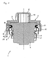
- FIGS 2 and 3 only show the handle part 7 of the Fuel cap 3, one in the middle up to the handle bar 8 reaching clutch cylinder 10 is available for a rotationally fixed connection between the grip part 7 and the engagement part 4 cares.
- the handle part 7 consists of a electrically conductive plastic, for example with Graphite particle offset polyamide.
- On the inside of the lower cylinder section 11 of the handle part 7 contact projections 12, 13 cast on diametrically opposite, which also consists of an electrically conductive Plastic.
- the contact protrusions 12, 13 are designed like a flag or leaf spring and on vertical Edges 14 with the cylinder section 11 by sprue connected. They are radial from these edges 14 facing inwards, being counter-clockwise from above seen - form ramps.
- the contact protrusions 12, 13 are so flexible that they dodge radially outwards can. They can pivot into recesses 15, 16.
- the recesses 15, 16 are designed that they completely receive the contact projections 12, 13 can.
- the undersides 17, 18 are towards the free end edges 19 bent up to form a curve 20. simultaneously are the undersides 17, 18 also in the direction of the Inside of the contact projections 12, 13 rounded.
- This Formation of the undersides 17, 18 of the contact projections 12, 13 serves that the contact projections 12, 13 at Screw the tank cap 3 onto the Slide the filler neck 2 and the stress in vertical direction is kept low and that a elongated line contact between contact protrusion 12, 13 and the tank neck 2 is obtained. This minimizes the electrical contact resistance there.
- the contact projections 12, 13 are bent radially outwards, so that in the end position of the tank cap 3 under Apply pre-tension to the tank neck 2.
Abstract
Description
- Figur 1
- einen Vertikalschnitt durch den erfindungsgemäßen Tankverschluß;
- Figur 2
- eine Seitenansicht schräg von unten des Griffteils des Tankverschlusses gemäß Figur 1 und
- Figur 3
- einen Vertikalschnitt durch das Griffteil gemäß Figur 2.
Claims (10)
- Tankverschluß (1) bestehend aus einem Tankdeckel (3) und einem elektrisch leitfähigen Tankstutzen (2), wobei der Tankdeckel (3) zu dessen Handhabung ein Griffteil (7) aus elektrisch leitfähigen Material aufweist, das elektrischen Kontakt mit wenigstens einem federnden, ebenfalls elektrisch leitfähigem Kontaktvorsprung (12, 13) hat, der im aufgeschraubten Zustand des Tankdeckels (3) an dem Tankstutzen (2) anliegt, dadurch gekennzeichnet, daß der Kontaktvorsprung bzw. die Kontaktvorsprünge (12, 13) an dem Griffteil (7) angeformt oder eingegossen ist bzw. sind.
- Tankverschluß nach Anspruch 1, dadurch gekennzeichnet, daß der Kontaktvorsprung bzw. die Kontaktvorsprünge (12, 13) aus elektrisch leitfähigem Kunststoff besteht bzw. bestehen.
- Tankverschluß nach Anspruch 1 oder 2, dadurch gekennzeichnet, daß das Griffteil (7) aus elektrisch leitfähigem Kunststoff besteht.
- Tankverschluß nach Anspruch 2 und 3, dadurch gekennzeichnet, daß der Kontaktvorsprung bzw. die Kontaktvorsprünge (12, 13) an das Griffteil (7) angegossen sind.
- Tankverschluß nach einem der Ansprüche 1 bis 4, dadurch gekennzeichnet, daß der Kontaktvorsprung bzw. die Kontaktvorsprünge (12, 13) blattfederartig ausgebildet ist bzw. sind und radial schräg nach innen vorstehen.
- Tankverschluß nach Anspruch 5, dadurch gekennzeichnet, daß der Kontaktvorsprung bzw. die Kontaktvorsprünge (12, 13) in einer Umfangsrichtung gesehen beginnend an der Innenseite des Griffteils (7) radial schräg nach innen vorstehen.
- Tankverschluß nach Anspruch 6, dadurch gekennzeichnet, daß die Unterseite (17, 18) des Kontaktvorsprungs bzw. der Kontaktvorsprünge (12, 13) zum freien Ende (19) hin hochgezogen und angeschrägt ist.
- Tankverschluß nach einem der Ansprüche 5 bis 7, dadurch gekennzeichnet, daß die Innenseite des Griffteils (7) im Bereich des Kontaktvorsprungs bzw. der Kontaktvorsprünge (12, 13) solche Ausnehmungen (15, 16) aufweist, daß der jeweilige Kontaktvorsprung (12, 13) bei Bewegung radial nach außen in die Ausnehmung (15, 16) paßt.
- Tankverschluß nach Anspruch 8, dadurch gekennzeichnet, daß der Kontaktvorsprung bzw. die Kontaktvorsprünge (12, 13) jeweils an einem Rand der Ausnehmung (15, 16) angeformt ist bzw. sind.
- Tankverschluß nach einem der Ansprüche 1 bis 9, dadurch gekennzeichnet, daß zwei Kontaktvorsprünge (12, 13) vorgesehen sind, die sich diametral gegenüberstehen.
Applications Claiming Priority (2)
| Application Number | Priority Date | Filing Date | Title |
|---|---|---|---|
| DE10317851 | 2003-04-16 | ||
| DE10317851A DE10317851A1 (de) | 2003-04-16 | 2003-04-16 | Tankverschluß |
Publications (1)
| Publication Number | Publication Date |
|---|---|
| EP1468858A1 true EP1468858A1 (de) | 2004-10-20 |
Family
ID=32892416
Family Applications (1)
| Application Number | Title | Priority Date | Filing Date |
|---|---|---|---|
| EP04008551A Withdrawn EP1468858A1 (de) | 2003-04-16 | 2004-04-08 | Tankverschluss |
Country Status (4)
| Country | Link |
|---|---|
| US (1) | US20050017009A1 (de) |
| EP (1) | EP1468858A1 (de) |
| JP (1) | JP2004315091A (de) |
| DE (1) | DE10317851A1 (de) |
Families Citing this family (4)
| Publication number | Priority date | Publication date | Assignee | Title |
|---|---|---|---|---|
| JP4490763B2 (ja) * | 2004-08-23 | 2010-06-30 | 本田技研工業株式会社 | 車両用燃料キャップ |
| US8086154B2 (en) * | 2008-10-23 | 2011-12-27 | Xerox Corporation | Nanomaterial heating element for fusing applications |
| NZ589025A (en) * | 2010-11-05 | 2011-09-30 | Stephen George Crowley | A fuel cap cover which connect via a cord a motor vehicle so it cannot be lost or misplaced |
| DE102013227125B4 (de) * | 2013-12-23 | 2016-04-07 | Senslab-Gesellschaft Zur Entwicklung Und Herstellung Bioelektrochemischer Sensoren Mbh | Verfahren zur Bestimmung eines hämatokritabhängigen Messsignals bei der Bestimmung eines Analyten aus Vollblut unter Verwendung von enzymatisch-voltammetrischen Einmalgebrauchs-Sensoren |
Citations (2)
| Publication number | Priority date | Publication date | Assignee | Title |
|---|---|---|---|---|
| WO1999005026A2 (en) * | 1997-07-23 | 1999-02-04 | Stant Manufacturing Inc. | Fuel cap |
| US6508374B1 (en) * | 1999-11-04 | 2003-01-21 | Stant Manufacturing Inc. | Filler neck closure with static charge dissipater |
Family Cites Families (5)
| Publication number | Priority date | Publication date | Assignee | Title |
|---|---|---|---|---|
| JP3200732B2 (ja) * | 1996-09-09 | 2001-08-20 | 豊田合成株式会社 | フューエルキャップ |
| JP3389850B2 (ja) * | 1997-03-31 | 2003-03-24 | 豊田合成株式会社 | 燃料キャップ |
| JPH11301290A (ja) * | 1998-04-17 | 1999-11-02 | Calsonic Corp | 燃料タンク用キャップ |
| US6325233B1 (en) * | 1998-10-06 | 2001-12-04 | Stant Manufacturing Inc. | Quick-on torque-override filler neck cap |
| JP3760841B2 (ja) * | 2001-11-12 | 2006-03-29 | 日産自動車株式会社 | フィラーキャップ構造 |
-
2003
- 2003-04-16 DE DE10317851A patent/DE10317851A1/de not_active Withdrawn
-
2004
- 2004-04-08 EP EP04008551A patent/EP1468858A1/de not_active Withdrawn
- 2004-04-15 US US10/824,640 patent/US20050017009A1/en not_active Abandoned
- 2004-04-16 JP JP2004120952A patent/JP2004315091A/ja active Pending
Patent Citations (2)
| Publication number | Priority date | Publication date | Assignee | Title |
|---|---|---|---|---|
| WO1999005026A2 (en) * | 1997-07-23 | 1999-02-04 | Stant Manufacturing Inc. | Fuel cap |
| US6508374B1 (en) * | 1999-11-04 | 2003-01-21 | Stant Manufacturing Inc. | Filler neck closure with static charge dissipater |
Also Published As
| Publication number | Publication date |
|---|---|
| US20050017009A1 (en) | 2005-01-27 |
| DE10317851A1 (de) | 2004-11-18 |
| JP2004315091A (ja) | 2004-11-11 |
Similar Documents
| Publication | Publication Date | Title |
|---|---|---|
| DE19714511B4 (de) | Anschlußstruktur für eine Speicherbatterie | |
| DE4446299C2 (de) | Elektrischer Batterieladesteckverbinder | |
| DE10012387C2 (de) | Anordnung zum Verbinden eines Kabels mit einem Kraftfahrzeugbatteriepol | |
| DE2549356C3 (de) | Zwischenfassung für das koaxiale Einlegen einer untermaßigen Batterie | |
| DE69833282T2 (de) | Kraftstofftankdeckel und Verfahren zu seiner Herstellung | |
| DE2632175A1 (de) | Einteilige kunststoffverschlusskappe | |
| DE102017128173A1 (de) | Stromabnehmer und Schleifleitungssystem | |
| DE69822240T2 (de) | Kraftstofftankdeckel | |
| DE3032718A1 (de) | Anschlussklemme fuer einen batteriepol | |
| DE10321492A1 (de) | Verbinder mit hervorragender Luftdichtigkeit und AGR-Sensor mit einem solchen Verbinder | |
| EP0240604A1 (de) | Isolierkanne mit einer elastischen Dichtung | |
| DE2409249B2 (de) | Deckel fuer feuerzeuge und damit ausgeruestetes feuerzeug | |
| DE1937989A1 (de) | Trimmpotentiometer fuer elektronische Schaltungen | |
| EP1837957A2 (de) | Bajonettverschluss mit Selbstkontaktierung | |
| EP1468858A1 (de) | Tankverschluss | |
| DE2919178A1 (de) | Polklemme | |
| DE19601740C2 (de) | Abgedichtete elektrische Steckverbindung | |
| DE2201347A1 (de) | Batterieverbinder | |
| EP1620926A1 (de) | Kontaktierungsanordnung | |
| DE202011000738U1 (de) | Verriegelungseinrichtung | |
| DD283878A5 (de) | Elektrische anschlussklemme mit gebremster schraube | |
| EP1319608B1 (de) | Behälter, insbesondere Paletteninnenbehälter | |
| DE2124115C3 (de) | Werkzeug zum Anbringen einer Verbinderhalfte am Außenleiter eines Koaxialkabels | |
| DE4343203C1 (de) | Mittelspannungs- oder Hochspannungsarmatur | |
| DE1465642A1 (de) | Elektrische Steckvorrichtung |
Legal Events
| Date | Code | Title | Description |
|---|---|---|---|
| PUAI | Public reference made under article 153(3) epc to a published international application that has entered the european phase |
Free format text: ORIGINAL CODE: 0009012 |
|
| AK | Designated contracting states |
Kind code of ref document: A1 Designated state(s): AT BE BG CH CY CZ DE DK EE ES FI FR GB GR HU IE IT LI LU MC NL PL PT RO SE SI SK TR |
|
| AX | Request for extension of the european patent |
Extension state: AL HR LT LV MK |
|
| 17P | Request for examination filed |
Effective date: 20040918 |
|
| 17Q | First examination report despatched |
Effective date: 20050222 |
|
| AKX | Designation fees paid |
Designated state(s): AT BE BG CH CY CZ DE DK EE ES FI FR GB GR HU IE IT LI LU MC NL PL PT RO SE SI SK TR |
|
| 17Q | First examination report despatched |
Effective date: 20050222 |
|
| GRAP | Despatch of communication of intention to grant a patent |
Free format text: ORIGINAL CODE: EPIDOSNIGR1 |
|
| STAA | Information on the status of an ep patent application or granted ep patent |
Free format text: STATUS: THE APPLICATION IS DEEMED TO BE WITHDRAWN |
|
| 18D | Application deemed to be withdrawn |
Effective date: 20110113 |