EP0197372A2 - Dispositif pour réguler le niveau d'un liquide, spécialement la hauteur d'eau - Google Patents
Dispositif pour réguler le niveau d'un liquide, spécialement la hauteur d'eau Download PDFInfo
- Publication number
- EP0197372A2 EP0197372A2 EP86103615A EP86103615A EP0197372A2 EP 0197372 A2 EP0197372 A2 EP 0197372A2 EP 86103615 A EP86103615 A EP 86103615A EP 86103615 A EP86103615 A EP 86103615A EP 0197372 A2 EP0197372 A2 EP 0197372A2
- Authority
- EP
- European Patent Office
- Prior art keywords
- partition
- trough
- pivot axis
- water
- spring
- Prior art date
- Legal status (The legal status is an assumption and is not a legal conclusion. Google has not performed a legal analysis and makes no representation as to the accuracy of the status listed.)
- Withdrawn
Links
- XLYOFNOQVPJJNP-UHFFFAOYSA-N water Substances O XLYOFNOQVPJJNP-UHFFFAOYSA-N 0.000 title claims abstract description 27
- 230000001105 regulatory effect Effects 0.000 title claims abstract description 8
- 239000007788 liquid Substances 0.000 title claims abstract description 6
- 238000005192 partition Methods 0.000 claims abstract description 37
- 230000006835 compression Effects 0.000 claims description 7
- 238000007906 compression Methods 0.000 claims description 7
- 238000007789 sealing Methods 0.000 claims description 5
- 230000004888 barrier function Effects 0.000 claims 1
- 238000010276 construction Methods 0.000 description 3
- 239000004033 plastic Substances 0.000 description 2
- 229920001875 Ebonite Polymers 0.000 description 1
- 239000011324 bead Substances 0.000 description 1
- 230000010354 integration Effects 0.000 description 1
- 238000003973 irrigation Methods 0.000 description 1
- 230000002262 irrigation Effects 0.000 description 1
Images

Classifications
-
- E—FIXED CONSTRUCTIONS
- E02—HYDRAULIC ENGINEERING; FOUNDATIONS; SOIL SHIFTING
- E02B—HYDRAULIC ENGINEERING
- E02B7/00—Barrages or weirs; Layout, construction, methods of, or devices for, making same
- E02B7/20—Movable barrages; Lock or dry-dock gates
- E02B7/205—Barrages controlled by the variations of the water level; automatically functioning barrages
Definitions
- the invention relates to a device for regulating a liquid, in particular water level, with a dividing wall which can be raised and lowered in a drain opening or gutter, the upper edge of which serves as an overflow.
- Such devices are generally known and are referred to as liquid or water weirs.
- the partition wall is raised or lowered depending on a water level measuring device, for example a pressure measuring device. This controls you with the partition or storage wall effectively connected drive for appropriate raising or lowering of the same, so that excess water can flow off over the upper edge of the partition or baffle.
- the present invention has for its object to provide a device of the type mentioned, which is characterized by minimal design effort with full functionality and low susceptibility to failure.
- the level control device according to claims 1 to 8 has proven to be a particularly simple yet effective construction.
- the simplest and most space-saving embodiment is a level control device with a coil spring arrangement. This can also be adjusted relatively well and precisely with regard to the spring strength.
- the device according to the invention is suitable both for integration in dams and for smaller irrigation systems or even laboratory facilities, that is to say wherever a certain liquid or water level should be maintained, and automatically regulating.
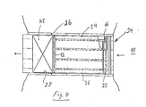
- the water weir shown schematically in Figures 1 to 4 is designed as a device for regulating the water level "h" of a reservoir or the like and comprises a partition 10 pivotally arranged in a trough 24, the upper edge of which serves as an overflow.
- the partition 10 is articulated on the bottom or bottom of the trough 24 with its lower or bottom edge 14 arranged opposite the upper overflow rim 12 to form a pivot axis 16 extending parallel thereto, and proceeding from this pivot axis 16 obliquely upwards from the water side 18 extending through a Level control device 20 held.
- the lower pivot axis 16 is covered in a fluid-tight manner by means of a flexible cover strip 22, for example made of plastic or rubber, so that no water can escape to the outside through the articulation or pivot axis region.
- a flexible cover strip 22 for example made of plastic or rubber.
- the partition wall 10 is sealed off from the upright side walls 26, 28 of the trough 24 by means of sealing strips 34, 36 arranged on the side edges 30, 32 of the same.
- sealing strips 34, 36 are arranged and designed such that they form a sealing bead protruding slightly beyond the side edge 30 or 32.
- the sealing strips are preferably made of plastic or rubber, in particular wear-resistant hard rubber.
- the level control device comprises a helical compression spring 38, which is traversed by a tension rod, one end of which is attached to the overflow edge 12 of the partition wall 10 and the other end of which is connected to the upper end of the compression spring 38, as shown in detail II in FIG. 1 recognizable.
- the compression spring 38 is arranged inside a cover sleeve 42 above the trough 24 in the region of the upper overflow rim 12 in a weather-protected manner.
- the tension rod passing through the helical compression spring 38 is identified in the detailed illustration II by the reference number 44.
- the tilting of the partition 10 and thus the opening of the trough 24 according to FIG. 2 can be adjusted after reaching a predetermined water level "h + h o ".
- the helical compression spring 38 is supported within the sleeve or the spring housing 42 on a lower end ring 46, which is likewise penetrated by the pull rod 44.
- a drain plate 48 is also articulated in order to avoid a waterfall-like overflow over the edge 12.
- the drainage plate 48 lies loosely on the edge of the drainage channel 24 with its edge facing away from the overflow edge 12, that is to say is supported on this back and forth. The drain plate 48 can thus easily follow the pivoting movements of the partition 10.
- a walking and / or driving bridge 50 is also guided over the trough 24. From this, the level control device 20 is easily accessible; this can be serviced by the bridge 50.
- the partition 10 When maintaining the device described, the partition 10 is preferably kept free of water.
- the trough 24 is blocked by an upright bulkhead 40. In this respect, it is a weir construction known per se (see FIG. 3).
Applications Claiming Priority (2)
| Application Number | Priority Date | Filing Date | Title |
|---|---|---|---|
| DE3512849 | 1985-04-10 | ||
| DE3512849 | 1985-04-10 |
Publications (2)
| Publication Number | Publication Date |
|---|---|
| EP0197372A2 true EP0197372A2 (fr) | 1986-10-15 |
| EP0197372A3 EP0197372A3 (fr) | 1987-04-29 |
Family
ID=6267634
Family Applications (1)
| Application Number | Title | Priority Date | Filing Date |
|---|---|---|---|
| EP86103615A Withdrawn EP0197372A3 (fr) | 1985-04-10 | 1986-03-18 | Dispositif pour réguler le niveau d'un liquide, spécialement la hauteur d'eau |
Country Status (3)
| Country | Link |
|---|---|
| US (1) | US4753550A (fr) |
| EP (1) | EP0197372A3 (fr) |
| FI (1) | FI861477A (fr) |
Cited By (1)
| Publication number | Priority date | Publication date | Assignee | Title |
|---|---|---|---|---|
| GB2451843A (en) * | 2007-08-14 | 2009-02-18 | Meiklewall Scotland Ltd | A barrier with a pivotably mounted cantilever member |
Families Citing this family (4)
| Publication number | Priority date | Publication date | Assignee | Title |
|---|---|---|---|---|
| US5208644A (en) * | 1990-05-18 | 1993-05-04 | Xinix, Inc. | Interference removal |
| US5156489A (en) * | 1991-10-03 | 1992-10-20 | The United States Of America As Represented By The Secretary Of Agriculture | Adjustable flume |
| JP5166311B2 (ja) * | 2009-02-04 | 2013-03-21 | 日本工営株式会社 | 開閉装置 |
| JP5166309B2 (ja) * | 2009-02-04 | 2013-03-21 | 日本工営株式会社 | 開閉装置 |
Citations (4)
| Publication number | Priority date | Publication date | Assignee | Title |
|---|---|---|---|---|
| CH195258A (fr) * | 1937-05-18 | 1938-01-31 | Eugene Frote | Barrage automatique. |
| US2118404A (en) * | 1937-01-28 | 1938-05-24 | Jermar Frantisek | Hydrostatic weir shutter |
| FR1217143A (fr) * | 1958-12-01 | 1960-05-02 | Entpr D Equipements Mecaniques | Vanne-clapet pour barrage hydraulique |
| US4455106A (en) * | 1981-10-23 | 1984-06-19 | Johnson William M | Flash gate board |
Family Cites Families (4)
| Publication number | Priority date | Publication date | Assignee | Title |
|---|---|---|---|---|
| US1443072A (en) * | 1921-04-11 | 1923-01-23 | Frye Harley Edgar | Movable dam |
| US2026656A (en) * | 1933-08-30 | 1936-01-07 | Krupp Ag Grusonwerk | Sluice weir |
| US2051359A (en) * | 1934-10-03 | 1936-08-18 | Jr James L Adams | Safety guard gate |
| GB1506079A (en) * | 1975-09-18 | 1978-04-05 | Nomura T | Water gate control system |
-
1986
- 1986-03-18 EP EP86103615A patent/EP0197372A3/fr not_active Withdrawn
- 1986-04-07 FI FI861477A patent/FI861477A/fi not_active IP Right Cessation
- 1986-10-14 US US06/918,558 patent/US4753550A/en not_active Expired - Fee Related
Patent Citations (4)
| Publication number | Priority date | Publication date | Assignee | Title |
|---|---|---|---|---|
| US2118404A (en) * | 1937-01-28 | 1938-05-24 | Jermar Frantisek | Hydrostatic weir shutter |
| CH195258A (fr) * | 1937-05-18 | 1938-01-31 | Eugene Frote | Barrage automatique. |
| FR1217143A (fr) * | 1958-12-01 | 1960-05-02 | Entpr D Equipements Mecaniques | Vanne-clapet pour barrage hydraulique |
| US4455106A (en) * | 1981-10-23 | 1984-06-19 | Johnson William M | Flash gate board |
Cited By (1)
| Publication number | Priority date | Publication date | Assignee | Title |
|---|---|---|---|---|
| GB2451843A (en) * | 2007-08-14 | 2009-02-18 | Meiklewall Scotland Ltd | A barrier with a pivotably mounted cantilever member |
Also Published As
| Publication number | Publication date |
|---|---|
| EP0197372A3 (fr) | 1987-04-29 |
| US4753550A (en) | 1988-06-28 |
| FI861477A0 (fi) | 1986-04-07 |
| FI861477A (fi) | 1986-10-11 |
Similar Documents
| Publication | Publication Date | Title |
|---|---|---|
| DE1559840A1 (de) | Rollenlager fuer Schiebefenster | |
| DE3338092C2 (fr) | ||
| DE2645288B2 (de) | Fahrzeugdach mit schwenkbarem Deckel | |
| DE3328294C2 (de) | Klappverdeck für Fahrzeuge, insbesondere Kraftfahrzeuge | |
| EP0197372A2 (fr) | Dispositif pour réguler le niveau d'un liquide, spécialement la hauteur d'eau | |
| DE1149627B (de) | Ausschwenkbar gelagerter Windabweiser an Kraftfahrzeugen mit Schiebedach | |
| DE3148849C2 (fr) | ||
| DE3842744A1 (de) | Schwimmergesteuerte regelvorrichtung | |
| DE8406312U1 (de) | Fenster oder tuer mit einer entwaesserungsvorrichtung fuer den fluegel- oder blendrahmen | |
| DE3044451C2 (de) | Fenstereinheit | |
| DE925929C (de) | Klappfenster fuer Fahrzeuge, insbesondere Oberlichtfenster fuer Kraftomnibusse | |
| DE3338793C2 (fr) | ||
| DE3022998C2 (de) | Regenüberlauf-Bauwerk für eine Mischkanalisation | |
| DE602004013432T2 (de) | Standregelung für flüssigkeitsdurchlauf | |
| EP0029468B2 (fr) | Dispositif de filtration à nettoyage par contre-courant | |
| EP0193620B1 (fr) | Dispositif pour collecter ou enlever de l'huile | |
| DE2751471C2 (de) | Vorrichtung zum selbsttätigen Ableiten der Flüssigkeit aus einem Regenfallrohr o.dgl. in einen Sammelbehälter | |
| DE462332C (de) | Wasserschnecke fuer die Foerderung des Wassers auf verschiedene Oberwasserstaende | |
| DE102005002986A1 (de) | Abdeckung für einen Hohlkörper | |
| DE215681C (fr) | ||
| DE1655725A1 (de) | Zu oeffnendes Fahrzeugdach mit Windabweiser | |
| DE489351C (de) | Walzenwehr mit Aufsatzklappe | |
| DE3234706A1 (de) | Vorrichtung zur beseitigung von verunreinigungen auf der oberflaeche von fluessigkeiten | |
| DE1287520B (de) | Stauklappe fuer ueberstroemte Wehre mit mindestens einem einstellbaren Strahlaufreisser | |
| DE1515341C (de) | Scharniergelenk für Abdeckplatten von Schleifleitungkanälen |
Legal Events
| Date | Code | Title | Description |
|---|---|---|---|
| PUAI | Public reference made under article 153(3) epc to a published international application that has entered the european phase |
Free format text: ORIGINAL CODE: 0009012 |
|
| AK | Designated contracting states |
Kind code of ref document: A2 Designated state(s): AT BE CH DE FR GB IT LI NL SE |
|
| PUAL | Search report despatched |
Free format text: ORIGINAL CODE: 0009013 |
|
| AK | Designated contracting states |
Kind code of ref document: A3 Designated state(s): AT BE CH DE FR GB IT LI NL SE |
|
| 17P | Request for examination filed |
Effective date: 19871020 |
|
| 17Q | First examination report despatched |
Effective date: 19890314 |
|
| STAA | Information on the status of an ep patent application or granted ep patent |
Free format text: STATUS: THE APPLICATION IS DEEMED TO BE WITHDRAWN |
|
| 18D | Application deemed to be withdrawn |
Effective date: 19890725 |