EP0197372A2 - Device for regulating a liquid level, especially a water level - Google Patents
Device for regulating a liquid level, especially a water level Download PDFInfo
- Publication number
- EP0197372A2 EP0197372A2 EP86103615A EP86103615A EP0197372A2 EP 0197372 A2 EP0197372 A2 EP 0197372A2 EP 86103615 A EP86103615 A EP 86103615A EP 86103615 A EP86103615 A EP 86103615A EP 0197372 A2 EP0197372 A2 EP 0197372A2
- Authority
- EP
- European Patent Office
- Prior art keywords
- partition
- trough
- pivot axis
- water
- spring
- Prior art date
- Legal status (The legal status is an assumption and is not a legal conclusion. Google has not performed a legal analysis and makes no representation as to the accuracy of the status listed.)
- Withdrawn
Links
- XLYOFNOQVPJJNP-UHFFFAOYSA-N water Substances O XLYOFNOQVPJJNP-UHFFFAOYSA-N 0.000 title claims abstract description 27
- 230000001105 regulatory effect Effects 0.000 title claims abstract description 8
- 239000007788 liquid Substances 0.000 title claims abstract description 6
- 238000005192 partition Methods 0.000 claims abstract description 37
- 230000006835 compression Effects 0.000 claims description 7
- 238000007906 compression Methods 0.000 claims description 7
- 238000007789 sealing Methods 0.000 claims description 5
- 230000004888 barrier function Effects 0.000 claims 1
- 238000010276 construction Methods 0.000 description 3
- 239000004033 plastic Substances 0.000 description 2
- 229920001875 Ebonite Polymers 0.000 description 1
- 239000011324 bead Substances 0.000 description 1
- 230000010354 integration Effects 0.000 description 1
- 238000003973 irrigation Methods 0.000 description 1
- 230000002262 irrigation Effects 0.000 description 1
Images

Classifications
-
- E—FIXED CONSTRUCTIONS
- E02—HYDRAULIC ENGINEERING; FOUNDATIONS; SOIL SHIFTING
- E02B—HYDRAULIC ENGINEERING
- E02B7/00—Barrages or weirs; Layout, construction, methods of, or devices for, making same
- E02B7/20—Movable barrages; Lock or dry-dock gates
- E02B7/205—Barrages controlled by the variations of the water level; automatically functioning barrages
Definitions
- the invention relates to a device for regulating a liquid, in particular water level, with a dividing wall which can be raised and lowered in a drain opening or gutter, the upper edge of which serves as an overflow.
- Such devices are generally known and are referred to as liquid or water weirs.
- the partition wall is raised or lowered depending on a water level measuring device, for example a pressure measuring device. This controls you with the partition or storage wall effectively connected drive for appropriate raising or lowering of the same, so that excess water can flow off over the upper edge of the partition or baffle.
- the present invention has for its object to provide a device of the type mentioned, which is characterized by minimal design effort with full functionality and low susceptibility to failure.
- the level control device according to claims 1 to 8 has proven to be a particularly simple yet effective construction.
- the simplest and most space-saving embodiment is a level control device with a coil spring arrangement. This can also be adjusted relatively well and precisely with regard to the spring strength.
- the device according to the invention is suitable both for integration in dams and for smaller irrigation systems or even laboratory facilities, that is to say wherever a certain liquid or water level should be maintained, and automatically regulating.
- the water weir shown schematically in Figures 1 to 4 is designed as a device for regulating the water level "h" of a reservoir or the like and comprises a partition 10 pivotally arranged in a trough 24, the upper edge of which serves as an overflow.
- the partition 10 is articulated on the bottom or bottom of the trough 24 with its lower or bottom edge 14 arranged opposite the upper overflow rim 12 to form a pivot axis 16 extending parallel thereto, and proceeding from this pivot axis 16 obliquely upwards from the water side 18 extending through a Level control device 20 held.
- the lower pivot axis 16 is covered in a fluid-tight manner by means of a flexible cover strip 22, for example made of plastic or rubber, so that no water can escape to the outside through the articulation or pivot axis region.
- a flexible cover strip 22 for example made of plastic or rubber.
- the partition wall 10 is sealed off from the upright side walls 26, 28 of the trough 24 by means of sealing strips 34, 36 arranged on the side edges 30, 32 of the same.
- sealing strips 34, 36 are arranged and designed such that they form a sealing bead protruding slightly beyond the side edge 30 or 32.
- the sealing strips are preferably made of plastic or rubber, in particular wear-resistant hard rubber.
- the level control device comprises a helical compression spring 38, which is traversed by a tension rod, one end of which is attached to the overflow edge 12 of the partition wall 10 and the other end of which is connected to the upper end of the compression spring 38, as shown in detail II in FIG. 1 recognizable.
- the compression spring 38 is arranged inside a cover sleeve 42 above the trough 24 in the region of the upper overflow rim 12 in a weather-protected manner.
- the tension rod passing through the helical compression spring 38 is identified in the detailed illustration II by the reference number 44.
- the tilting of the partition 10 and thus the opening of the trough 24 according to FIG. 2 can be adjusted after reaching a predetermined water level "h + h o ".
- the helical compression spring 38 is supported within the sleeve or the spring housing 42 on a lower end ring 46, which is likewise penetrated by the pull rod 44.
- a drain plate 48 is also articulated in order to avoid a waterfall-like overflow over the edge 12.
- the drainage plate 48 lies loosely on the edge of the drainage channel 24 with its edge facing away from the overflow edge 12, that is to say is supported on this back and forth. The drain plate 48 can thus easily follow the pivoting movements of the partition 10.
- a walking and / or driving bridge 50 is also guided over the trough 24. From this, the level control device 20 is easily accessible; this can be serviced by the bridge 50.
- the partition 10 When maintaining the device described, the partition 10 is preferably kept free of water.
- the trough 24 is blocked by an upright bulkhead 40. In this respect, it is a weir construction known per se (see FIG. 3).
Abstract
Vorrichtung zur Regelung einer Flüssigkeit- insbesondere Wasserstandshöhe, mit einer in einer Abflußrinne (24) angeordneten Trennwand (10), deren oberer Rand (12) als Überlauf dient. Die Trennwand (10) ist an ihrem dem oberen Überlaufrand (12) gegenüberliegend angeordneten unteren bzw. bodenseitigen Rand (14) am Boden der Abflußrinne (24) schwenkbar gelagert (Schwenkachse 16) sowie ausgehend vom Boden der Abflußrinne (24) sich schräg nach oben von der Wasserseite (18) weg erstreckend durch eine Niveaureguliereinrichtung (20) gehalten.Device for regulating a liquid, in particular water level, with a partition (10) arranged in a trough (24), the upper edge (12) of which serves as an overflow. The partition (10) is pivotally mounted on its bottom or bottom edge (14) opposite the upper overflow edge (12) on the bottom of the trough (24) (pivot axis 16) and starting from the bottom of the trough (24) is inclined upwards held by a level control device (20) extending from the water side (18).
Description
Die Erfindung betrifft eine Vorrichtung zur Regelung einer Flüssigkeit-,insbesondere Wasserstandshöhe, mit einer in einer Abflußöffnung oder -rinne heb- und senkbar angeordneten Trennwand, deren oberer Rand als Überlauf dient.The invention relates to a device for regulating a liquid, in particular water level, with a dividing wall which can be raised and lowered in a drain opening or gutter, the upper edge of which serves as an overflow.
Derartige Vorrichtungen sind allgemein bekannt und werden als Flüssigkeits- bzw. Wasserwehr bezeichnet. Das Anheben oder Absenken der Trenn- bzw. Stauwand erfolgt in Abhängigkeit eines Wasserstands-Meßgerätes, zum Beispiel Druckmeßgerätes. Dieses steuert einen mit der Trenn- bzw. Stauwand wirksam verbundenen Antrieb zum entsprechenden Anheben oder Absenken derselben, so daß überschüssiges Wasser über die obere Kante der Trenn- bzw. Stauwand abfließen kann.Such devices are generally known and are referred to as liquid or water weirs. The partition wall is raised or lowered depending on a water level measuring device, for example a pressure measuring device. This controls you with the partition or storage wall effectively connected drive for appropriate raising or lowering of the same, so that excess water can flow off over the upper edge of the partition or baffle.
Diese Regelung der Wasserstandshöhe ist relativ konstruktions- sowie steuerungsaufwendig und dementsprechend störanfällig.This regulation of the water level is relatively complex in terms of construction and control, and accordingly prone to failure.
Ausgehend von diesem Stand der Technik liegt der vorliegenden Erfindung die Aufgabe zugrunde, eine Vorrichtung der eingangs genannten Art zu schaffen, die sich durch minimalen Konstruktionsaufwand bei voller Funktionsfähigkeit und geringer Störanfälligkeit auszeichnet.Starting from this prior art, the present invention has for its object to provide a device of the type mentioned, which is characterized by minimal design effort with full functionality and low susceptibility to failure.
Diese Aufgabe wird in überraschend einfacher Weise durch die kennzeichnenden Maßnahmen nach Patentanspruch 1 gelöst.This object is achieved in a surprisingly simple manner by the characterizing measures according to claim 1.
Durch die sich schräg nach oben und von* der Wasserseite weg erstreckende Anordnung der Trennwand wird eine direkte Wasserstandsregelung erhalten im Gegensatz zu der indirekten Regelung nach dem Stand der Technik. Die auf der Trennwand "stehende Wassersäule" wirkt unmittelbar auf die der Trennwand zugeordnete Niveaureguliereinrichtung. Aus diesem Grunde sind der Konstruktionsaufwand und die Störanfälligkeit minimal bei voller Funktionsfähigkeit.Due to the arrangement of the partition wall that extends obliquely upwards and away from the water side, a direct water level control is obtained in contrast to the indirect control according to the prior art. The "standing water column" on the partition acts directly on the level control device assigned to the partition. For this reason, the design effort and the susceptibility to failure are minimal with full functionality.
Konstruktive Details der Erfindung sind in den Unteransprüchen beschrieben..Als eine besonders einfache und dennoch wirkungsvolle Konstruktion hat sich die Niveaureguliereinrichtung nach den Ansprüchen 1 bis 8 erwiesen. Die einfachste und platzsparendste Ausführungsform ist eine Niveaureguliereinrichtung mit einer Schraubenfederanordnung. Diese ist auch hinsichtlich der Federstärke relativ gut und genau einstellbar.Structural details of the invention are described in the subclaims. The level control device according to claims 1 to 8 has proven to be a particularly simple yet effective construction. The simplest and most space-saving embodiment is a level control device with a coil spring arrangement. This can also be adjusted relatively well and precisely with regard to the spring strength.
Die erfindungsgemäße Vorrichtung eigent sich sowohl für die Integration in Staudämmen als auch für kleinere Bewässerungsanlagen oder gar Laboreinrichtungen, also überall dort, wo eine bestimmte Flüssigkeits- bzw. Wasserstandshöhe eingehalten werden soll, und zwar selbsttätig regulierend.The device according to the invention is suitable both for integration in dams and for smaller irrigation systems or even laboratory facilities, that is to say wherever a certain liquid or water level should be maintained, and automatically regulating.
Nachstehend wird eine bevorzugte Ausführungsform der erfindungsgemäßen Vorrichtung anhand der beigefügten Zeichnung näher beschrieben.A preferred embodiment of the device according to the invention is described below with reference to the accompanying drawing.
Es zeigen:
- Fig. 1 eine Vorrichtung gemäß Erfindung in schematischer Seitenansicht, wobei bei Betrachtung der Fig. 1 vordere Seitenwand der Abflußrinne, in der die erfindungsgemäße Vorrichtung angeordnet ist, weg- gelassen ist;
- Fig. 2 die Vorrichtung nach Fig. 1 in entsprechender Darstellung mit geöffneter Trennwand;
- Fig. 3 die Vorrichtung nach Fig. 1 in entsprechender Darstellung, wobei die.Abflußrinne durch eine aufrechte Schottwand abgesperrt ist;
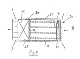
- Fig. 4 die Vorrichtung nach Fig. 1 in Draufsicht, und
- Fig. 5 ein Detail der Trennwand nach Fig. 1 im Schnitt sowie vergrößertem Maßstab.
- Fig. 1 shows a device invention in a schematic side view, with clear upon consideration of FIG 1 front side wall of the trough, in which the inventive device is arranged according to - is allowed;.
- Fig. 2 shows the device of Figure 1 in a corresponding representation with the partition open;
- Fig. 3 shows the device of Figure 1 in a corresponding representation, the drain trough is blocked by an upright bulkhead.
- F ig. 4 shows the device according to FIG. 1 in plan view, and
- Fig. 5 shows a detail of the partition of Fig. 1 in section and on an enlarged scale.
Das in den Figuren 1 bis 4 schematisch dargestellte Wasserwehr ist als Vorrichtung zur Regelung der Wasserstandshöhe "h" eines Stausees oder dergleichen ausgebildet und umfaßt eine in einer Abflußrinne 24 schwenkbar angeordnete Trennwand 10, deren oberer Rand als Überlauf dient. Die Trennwand 10 ist am Boden bzw. Grund der Abflußrinne 24 mit ihrem dem oberen Uberlaufrand 12 gegenüberliegend angeordneten unteren bzw. bodenseitigen Rand 14 unter Ausbildung einer sich parallel dazu erstreckenden Schwenkachse 16 angelenkt und ausgehend von dieser Schwenkachse 16 sich schräg nach oben von der Wasserseite 18 weg erstreckend durch eine Niveaureguliereinrichtung 20 gehalten. Die untere Schwenkachse 16 ist fluiddicht mittels eines flexiblen Deckstreifens 22, zum Beispiel aus Kunststoff oder Gummi, abgedeckt, so daß durch den Anlenkungs- bzw. Schwenkachsenbereich kein Wasser nach außen dringen kann. Die Abdeckung des Schwenkachsenbereiches ist in Fig. 1 als Detaildarstellung I in vergrößertem Maßstab dargestellt.The water weir shown schematically in Figures 1 to 4 is designed as a device for regulating the water level "h" of a reservoir or the like and comprises a
Gegenüber den aufrechten Seitenwänden 26, 28 der Abflußrinne 24 ist die Trennwand 10 mittels an den Seitenrändern 30, 32 derselben angeordneten Dichtleisten 34, 36 abgedichtet. Es wird dazu auf die Darstellung in Fig. 5 verwiesen. Die Dichtleisten 34, 36 sind so angeordnet und ausgebildet, daß sie einen über den Seitenrand 30 bzw. 32 geringfügig vorstehenden Dichtwulst bilden. Die Dichtleisten bestehen vorzugsweise aus Kunststoff oder Gummi, insbesondere ver- schleißfestem Hartgummi.The
Der obere Überlaufrand 12 der Trennwand 10 ist an der bereits erwähnten Niveaureguliereinrichtung 20 angeschlossen. Dadurch wird der öffnungswiderstand der Trennwand 10 bestimmt. Bei dem dargestellten Ausführungsbeispiel umfaßt die Niveaureguliereinrichtung eine Schraubendruckfeder 38, die von einem Zugstab durchsetzt ist, dessen eines Ende am Überlaufrand 12 der Trennwand 10 befestigt und dessen andere Ende mit dem oberen Ende der Druckfeder 38 verbunden ist, wie in der Detaildarstellung II in Fig. 1 erkennbar. Die Druckfeder 38 ist innerhalb einer Abdeckhülse 42 oberhalb der Abflußrinne 24 im Bereich des oberen Uberlaufrandes 12 witterungsgeschützt angeordnet. Der die Schraubendruckfeder 38 durchsetzende Zugstab ist in der Detaildarstellung II mit der Bezugsziffer 44 gekennzeichnet.The
Durch entsprechende Einstellung der Federhärte bzw. Wahl der Druckfeder 38 ist das Abkippen der Trennwand 10 und damit das öffnen der Abflußrinne 24 entsprechend Fig. 2 nach Erreichen einer vorgegebenen Wasserstandshöhe "h + ho" einstellbar.By appropriate adjustment of the spring hardness or choice of the
Die Abstützung der Schraubendruckfeder 38 innerhalb der Hülse bzw. des Federgehäuses 42 erfolgt an einem unteren Abschlußring 46, der ebenfalls von der Zugstange 44 durchsetzt ist.The
Am oberen überlaufrand 12 der Trennwand 10 ist noch eine Abflußplatte 48 angelenkt, um einen wasserfallartigen Uberlauf über die Kante 12 zu vermeiden. Die Abflußplatte 48 liegt dabei mit ihrem der überlaufkante 12 abgewandten Rand auf dem Boden der Abflußrinne 24 lose auf, das heißt, ist auf diesem hin- und hergleitend abgestützt. Die Abflußplatte 48 kann damit den Schwenkbewegungen der Trennwand 10 mühelos folgen.At the
über die Abflußrinne 24 ist bei dem dargestellten Ausführungsbeispiel noch eine Geh- und/oder Fahrbrücke 50 geführt. Von dieser ist die Niveaureguliereinrichtung 20 gut zugänglich; diese kann von der Brücke 50 gewartet werden.In the illustrated embodiment, a walking and / or
Bei der Wartung der beschriebenen Vorrichtung wird die Trennwand 10 vorzugsweise von Wasser freigehalten. Zu diesem Zweck wird die Abflußrinne 24 durch eine aufrechte Schottwand 40 abgesperrt. Insofern handelt es sich um eine an sich bekannte Wehrkonstruktion (siehe Fig. 3).When maintaining the device described, the
Sämtliche in den Unterlagen offenbarten Merkmale werden als erfindungswesentlich beansprucht, so weit sie einzeln oder in Kombination gegenüber dem Stand der Technik neu sind.All features disclosed in the documents are claimed as essential to the invention, insofar as they are new compared to the prior art, individually or in combination.
Claims (12)
Applications Claiming Priority (2)
| Application Number | Priority Date | Filing Date | Title |
|---|---|---|---|
| DE3512849 | 1985-04-10 | ||
| DE3512849 | 1985-04-10 |
Publications (2)
| Publication Number | Publication Date |
|---|---|
| EP0197372A2 true EP0197372A2 (en) | 1986-10-15 |
| EP0197372A3 EP0197372A3 (en) | 1987-04-29 |
Family
ID=6267634
Family Applications (1)
| Application Number | Title | Priority Date | Filing Date |
|---|---|---|---|
| EP86103615A Withdrawn EP0197372A3 (en) | 1985-04-10 | 1986-03-18 | Device for regulating a liquid level, especially a water level |
Country Status (3)
| Country | Link |
|---|---|
| US (1) | US4753550A (en) |
| EP (1) | EP0197372A3 (en) |
| FI (1) | FI861477A (en) |
Cited By (1)
| Publication number | Priority date | Publication date | Assignee | Title |
|---|---|---|---|---|
| GB2451843A (en) * | 2007-08-14 | 2009-02-18 | Meiklewall Scotland Ltd | A barrier with a pivotably mounted cantilever member |
Families Citing this family (4)
| Publication number | Priority date | Publication date | Assignee | Title |
|---|---|---|---|---|
| US5208644A (en) * | 1990-05-18 | 1993-05-04 | Xinix, Inc. | Interference removal |
| US5156489A (en) * | 1991-10-03 | 1992-10-20 | The United States Of America As Represented By The Secretary Of Agriculture | Adjustable flume |
| JP5166309B2 (en) * | 2009-02-04 | 2013-03-21 | 日本工営株式会社 | Switchgear |
| JP5166311B2 (en) * | 2009-02-04 | 2013-03-21 | 日本工営株式会社 | Switchgear |
Citations (4)
| Publication number | Priority date | Publication date | Assignee | Title |
|---|---|---|---|---|
| CH195258A (en) * | 1937-05-18 | 1938-01-31 | Eugene Frote | Automatic barrage. |
| US2118404A (en) * | 1937-01-28 | 1938-05-24 | Jermar Frantisek | Hydrostatic weir shutter |
| FR1217143A (en) * | 1958-12-01 | 1960-05-02 | Entpr D Equipements Mecaniques | Hydraulic shut-off valve |
| US4455106A (en) * | 1981-10-23 | 1984-06-19 | Johnson William M | Flash gate board |
Family Cites Families (4)
| Publication number | Priority date | Publication date | Assignee | Title |
|---|---|---|---|---|
| US1443072A (en) * | 1921-04-11 | 1923-01-23 | Frye Harley Edgar | Movable dam |
| US2026656A (en) * | 1933-08-30 | 1936-01-07 | Krupp Ag Grusonwerk | Sluice weir |
| US2051359A (en) * | 1934-10-03 | 1936-08-18 | Jr James L Adams | Safety guard gate |
| GB1506079A (en) * | 1975-09-18 | 1978-04-05 | Nomura T | Water gate control system |
-
1986
- 1986-03-18 EP EP86103615A patent/EP0197372A3/en not_active Withdrawn
- 1986-04-07 FI FI861477A patent/FI861477A/en not_active IP Right Cessation
- 1986-10-14 US US06/918,558 patent/US4753550A/en not_active Expired - Fee Related
Patent Citations (4)
| Publication number | Priority date | Publication date | Assignee | Title |
|---|---|---|---|---|
| US2118404A (en) * | 1937-01-28 | 1938-05-24 | Jermar Frantisek | Hydrostatic weir shutter |
| CH195258A (en) * | 1937-05-18 | 1938-01-31 | Eugene Frote | Automatic barrage. |
| FR1217143A (en) * | 1958-12-01 | 1960-05-02 | Entpr D Equipements Mecaniques | Hydraulic shut-off valve |
| US4455106A (en) * | 1981-10-23 | 1984-06-19 | Johnson William M | Flash gate board |
Cited By (1)
| Publication number | Priority date | Publication date | Assignee | Title |
|---|---|---|---|---|
| GB2451843A (en) * | 2007-08-14 | 2009-02-18 | Meiklewall Scotland Ltd | A barrier with a pivotably mounted cantilever member |
Also Published As
| Publication number | Publication date |
|---|---|
| FI861477A (en) | 1986-10-11 |
| FI861477A0 (en) | 1986-04-07 |
| EP0197372A3 (en) | 1987-04-29 |
| US4753550A (en) | 1988-06-28 |
Similar Documents
| Publication | Publication Date | Title |
|---|---|---|
| DE1559840A1 (en) | Roller bearings for sliding windows | |
| DE3338092C2 (en) | ||
| DE2645288B2 (en) | Vehicle roof with swiveling cover | |
| DE3328294C2 (en) | Folding roofs for vehicles, in particular motor vehicles | |
| EP0197372A2 (en) | Device for regulating a liquid level, especially a water level | |
| DE1149627B (en) | Swivel-mounted wind deflector on motor vehicles with a sliding roof | |
| DE3148849C2 (en) | ||
| DE3842744A1 (en) | FLOAT CONTROLLED CONTROL DEVICE | |
| DE8406312U1 (en) | WINDOW OR DOOR WITH A DRAINAGE DEVICE FOR THE LEAF OR FRAME FRAME | |
| DE3044451C2 (en) | Window unit | |
| DE925929C (en) | Top-hung windows for vehicles, especially skylight windows for buses | |
| DE3338793C2 (en) | ||
| DE3022998C2 (en) | Rain overflow structure for a mixed sewer system | |
| DE602004013432T2 (en) | LIQUID FLOW CONTROL | |
| EP0029468B2 (en) | Back-wash filter assembly | |
| EP0193620B1 (en) | Device for collecting or picking up oil | |
| DE2751471C2 (en) | Device for the automatic drainage of the liquid from a downpipe or the like. into a collecting container | |
| DE462332C (en) | Water screw for the pumping of the water to various headwater levels | |
| DE102005002986A1 (en) | Cover for a hollow body | |
| DE1655725A1 (en) | Vehicle roof that can be opened with wind deflector | |
| DE489351C (en) | Roller weir with attachment flap | |
| DE3234706A1 (en) | Apparatus for removal of impurities on the surface of liquids | |
| DE1287520B (en) | Damming flap for overflowing weirs with at least one adjustable jet ripper | |
| DE1515341C (en) | Hinge joint for cover plates of conductor rail ducts | |
| DE1480559C (en) | Device for raising and lowering the sliding cover of rigid vehicle sunroofs |
Legal Events
| Date | Code | Title | Description |
|---|---|---|---|
| PUAI | Public reference made under article 153(3) epc to a published international application that has entered the european phase |
Free format text: ORIGINAL CODE: 0009012 |
|
| AK | Designated contracting states |
Kind code of ref document: A2 Designated state(s): AT BE CH DE FR GB IT LI NL SE |
|
| PUAL | Search report despatched |
Free format text: ORIGINAL CODE: 0009013 |
|
| AK | Designated contracting states |
Kind code of ref document: A3 Designated state(s): AT BE CH DE FR GB IT LI NL SE |
|
| 17P | Request for examination filed |
Effective date: 19871020 |
|
| 17Q | First examination report despatched |
Effective date: 19890314 |
|
| STAA | Information on the status of an ep patent application or granted ep patent |
Free format text: STATUS: THE APPLICATION IS DEEMED TO BE WITHDRAWN |
|
| 18D | Application deemed to be withdrawn |
Effective date: 19890725 |