EP0196691A1 - Dispositif électro-optique - Google Patents
Dispositif électro-optique Download PDFInfo
- Publication number
- EP0196691A1 EP0196691A1 EP86200309A EP86200309A EP0196691A1 EP 0196691 A1 EP0196691 A1 EP 0196691A1 EP 86200309 A EP86200309 A EP 86200309A EP 86200309 A EP86200309 A EP 86200309A EP 0196691 A1 EP0196691 A1 EP 0196691A1
- Authority
- EP
- European Patent Office
- Prior art keywords
- objective
- axis
- turntable
- tilting
- disk
- Prior art date
- Legal status (The legal status is an assumption and is not a legal conclusion. Google has not performed a legal analysis and makes no representation as to the accuracy of the status listed.)
- Granted
Links
Images


Classifications
-
- G—PHYSICS
- G11—INFORMATION STORAGE
- G11B—INFORMATION STORAGE BASED ON RELATIVE MOVEMENT BETWEEN RECORD CARRIER AND TRANSDUCER
- G11B7/00—Recording or reproducing by optical means, e.g. recording using a thermal beam of optical radiation by modifying optical properties or the physical structure, reproducing using an optical beam at lower power by sensing optical properties; Record carriers therefor
- G11B7/08—Disposition or mounting of heads or light sources relatively to record carriers
-
- G—PHYSICS
- G11—INFORMATION STORAGE
- G11B—INFORMATION STORAGE BASED ON RELATIVE MOVEMENT BETWEEN RECORD CARRIER AND TRANSDUCER
- G11B17/00—Guiding record carriers not specifically of filamentary or web form, or of supports therefor
- G11B17/32—Maintaining desired spacing between record carrier and head, e.g. by fluid-dynamic spacing
-
- G—PHYSICS
- G11—INFORMATION STORAGE
- G11B—INFORMATION STORAGE BASED ON RELATIVE MOVEMENT BETWEEN RECORD CARRIER AND TRANSDUCER
- G11B19/00—Driving, starting, stopping record carriers not specifically of filamentary or web form, or of supports therefor; Control thereof; Control of operating function ; Driving both disc and head
- G11B19/20—Driving; Starting; Stopping; Control thereof
- G11B19/2009—Turntables, hubs and motors for disk drives; Mounting of motors in the drive
-
- G—PHYSICS
- G11—INFORMATION STORAGE
- G11B—INFORMATION STORAGE BASED ON RELATIVE MOVEMENT BETWEEN RECORD CARRIER AND TRANSDUCER
- G11B7/00—Recording or reproducing by optical means, e.g. recording using a thermal beam of optical radiation by modifying optical properties or the physical structure, reproducing using an optical beam at lower power by sensing optical properties; Record carriers therefor
- G11B7/002—Recording, reproducing or erasing systems characterised by the shape or form of the carrier
- G11B7/0037—Recording, reproducing or erasing systems characterised by the shape or form of the carrier with discs
-
- G—PHYSICS
- G11—INFORMATION STORAGE
- G11B—INFORMATION STORAGE BASED ON RELATIVE MOVEMENT BETWEEN RECORD CARRIER AND TRANSDUCER
- G11B7/00—Recording or reproducing by optical means, e.g. recording using a thermal beam of optical radiation by modifying optical properties or the physical structure, reproducing using an optical beam at lower power by sensing optical properties; Record carriers therefor
- G11B7/08—Disposition or mounting of heads or light sources relatively to record carriers
- G11B7/085—Disposition or mounting of heads or light sources relatively to record carriers with provision for moving the light beam into, or out of, its operative position or across tracks, otherwise than during the transducing operation, e.g. for adjustment or preliminary positioning or track change or selection
- G11B7/0857—Arrangements for mechanically moving the whole head
- G11B7/08582—Sled-type positioners
-
- G—PHYSICS
- G11—INFORMATION STORAGE
- G11B—INFORMATION STORAGE BASED ON RELATIVE MOVEMENT BETWEEN RECORD CARRIER AND TRANSDUCER
- G11B7/00—Recording or reproducing by optical means, e.g. recording using a thermal beam of optical radiation by modifying optical properties or the physical structure, reproducing using an optical beam at lower power by sensing optical properties; Record carriers therefor
- G11B7/08—Disposition or mounting of heads or light sources relatively to record carriers
- G11B7/09—Disposition or mounting of heads or light sources relatively to record carriers with provision for moving the light beam or focus plane for the purpose of maintaining alignment of the light beam relative to the record carrier during transducing operation, e.g. to compensate for surface irregularities of the latter or for track following
- G11B7/095—Disposition or mounting of heads or light sources relatively to record carriers with provision for moving the light beam or focus plane for the purpose of maintaining alignment of the light beam relative to the record carrier during transducing operation, e.g. to compensate for surface irregularities of the latter or for track following specially adapted for discs, e.g. for compensation of eccentricity or wobble
- G11B7/0956—Disposition or mounting of heads or light sources relatively to record carriers with provision for moving the light beam or focus plane for the purpose of maintaining alignment of the light beam relative to the record carrier during transducing operation, e.g. to compensate for surface irregularities of the latter or for track following specially adapted for discs, e.g. for compensation of eccentricity or wobble to compensate for tilt, skew, warp or inclination of the disc, i.e. maintain the optical axis at right angles to the disc
Definitions
- the invention relates to an electro-optical device for recording and/or reading recording tracks in a recording surface of an optically readable disk by means of a radiation beam, the recording surface of the disk being provided with a transparent coating having a plane surface
- electro-optical device comprises a frame, a turntable supporting means for a turntable which is rotatable about an axis of rotation, an objective supporting means for an objective having an optical axis, which objective comprises a lens system for concentrating the radiation beam to form a radiation spot, a focussing actuator for moving the objective along the optical axis, mechanical guide means for at least one of the supporting means, for moving the objective and the turntable relative to each other in a radial direction between a first position, in which they are situated nearer each other, and a second position, in which they are situated more remote from each other, and correction means for reducing the angle between the optical axis of the objective and the normal to the disk surface at the location of the intersection of the optical axis and the disk surface in the case of an
- Such an electro-optical device is described in Netherlands Patent Application 8105072 (PHN.10.183), herewith incorporated by reference, and may be employed, for example, in optical video-disk players, optical audio-disk players and optical storage-disk apparatus.
- the radiation beam is produced by a laser and is concentrated by means of the objective to form a light spot of very small dimensions.
- the minimum size of the light spot is dictated by the wavelength of the light source and the numerical aperture of the lens system of the objective.
- the light in the light spot comprises a brighter central portion surrounded by concentric rings of substantially lower intensity. When the centre of the light spot is situated on a recording track some of the light is also incident on the adjacent tracks.
- the reflected light not only contains the information from the desired recording track but also information from adjacent recording tracks.
- the reflected light is received and detected by light-sensitive electronic means of the disk-record player for deriving an electric signal corresponding to the information in the reflected light.
- the resulting crosstalk between adjacent recording tracks depends largely on the light distribution in the light spot on the recording surface.
- the light distribution in the light spot is influenced by not only the optical quality of the optical system by means of which the light spot is formed and the quality of the light source itself but also by any oblique orientation of the disk surface. This obliquity mainly gives rise to coma and an increased intensity at one side of the central portion, namely in the direction in which the disk surface is oriented obliquely.
- the surface of the disk is oriented obliquely in a radial direction this results in increased crosstalk between the recording track scanned by the light spot and an adjacent recording track.
- Tests have shown that if an HeNe laser is employed in an optical video recorder intended for normal home-entertainment use the obliquity of the disk should not exceed 1°. However, if an AlGaAs laser is employed, which is substantially smaller and cheaper, the obliquity should be less than 0.5°.
- the reduction in permissible obliquity of the disk in the case of an AlGaAs laser is closely related to the fact that for the same optical bandwidth the numerical aperture of the objective is larger than in the case of an HeNe laser.
- the obliquity of an optically readable disk depends on several factors, such as tolerances in the manufacture of the disk player and the disk.
- the obliquity of the disk in a radial direction has a substantial influence on the crosstalk between the recording tracks and this obliquity is caused mainly by deviations in flatness of the surface of the disk as a result of its own weight.
- material stresses in the optically readable multi-layer disk may give rise to a paraboloid-like shape, which also leads to a radial obliquity.
- the known electro-optical device comprises automatic correction means for continually and automatically correcting the neutral position of the optical axis during recording and/or reading of the recording tracks by tilting the objective about a pivotal axis perpendicular to the optical axis through a correction angle which is related to the direction of the normal to the surface of the optical disk at the location of the intersection of the surface of the optical disk with the optical axis of the objective, in order to minimize the angle between the optical axis and said normal in the case of obliquity of the surface.
- the obliquity of the optical disk is not changed, but its effect on the crosstalk between adjacent recording tracks is reduced by correcting the position of the objective relative to the surface of the optical disk.
- the objective supporting means comprises a stationary supporting member which is secured to the frame and a second supporting member on which the objective is mounted and which is movable relative to the first supporting member.
- This electro-optical device further comprises an electrical focussing actuator for moving the objective along the optical axis from a neutral position of the objective relative to the stationary supporting member, in order to focus the radiation spot onto the recording surface.
- the use of a focussing actuator is customary in optical disk-record players in view of the very small depth of focus of the objectives used.
- the depth of focus is of the order of a few micrometres, so that the inevitable small variations in the position of the recording surface can be followed by means of an automatic focussing system.
- the focussing actuator moves the objective to and fro along its optical axis, whilst the objective supporting means of the known electro-optical device ensures that during the focussing movements of the objective the objective is tilted depending on its position.
- the objective should be capable of performing a large displacement along its optical axis from a neutral position relative to the stationary supporting member, in order to permit the radially inclined surface of the disk to be followed.
- the objective should be capable of performing small displacements rapidly and frequently along its optical axis to enable local irregularities in the position of the recording surface to be followed. Constructing an actuator which is capable of providing both said large displacement and said small displacements of the objective in an adequate manner is a difficult technical problem.
- the invention aims at providing an electro-optical device of the type specified in the opening paragraph, in which for the correction of the obliquity of the optically readable disk during recording and/or reading of the recording tracks it is, in principle, not necessary to use the focussing actuator for adapting the position of the objective to the said obliquity.
- the correction means comprise a tilting device for tilting, during the recording and/or reading of the recording tracks, at least one of the two supporting means relative to a neutral position about a pivotal axis, which pivotal.axis extends at least substantially transversely of a plane which is defined by the optical axis and the axis of rotation and which pivotal axis, at least in the second position of the objective and the turntable, is situated between the axis of rotation and the optical axis, through a tilting angle which is related to the direction of said normal to said surface of the optical disk.
- the electro-optical device therefore enables crosstalk between adjacent recording tracks to be reduced either by correcting the position of the objective supporting means together with the objective relative to the surface of the optical disk or by changing the obliquity of the optical disk itself by changing the position of the turntable supporting means together with the turntable, whilst it is also possible to utilize a combination of these two possibilities.
- the tilting device may be driven, for example, by an electrical drive unit, which is electrically.coupled to an angular-position detector for detecting the obliquity of the disk, so that there is a direct relationship between the angles through which the objective supporting means and/or the turntable supporting means have to be tilted and the angle between said normal to the disk surface and the optical axis.
- the deviations may be classified in two categories, of which a first category concerns the direction of the normal to said surface at the location of the recording tracks. These deviations are also referred to as angular deviations. The second category of deviations concerns the level at which the recording tracks are situated. These deviations are also referred to as height deviations. Both categories may occur at high frequencies and at low frequencies.
- the focussing actuator can be smaller than is possible with the known device.
- a smaller dimension is possible at least in the axial direction because the focussing actuator need only be capable of moving the objective along the optical axis over a limited travel.
- a shorter and flatter focussing actuator has the direct advantage of lower mass and, consequently, a higher efficiency.
- An optical disk-record player employing an electro-optical device in accordance with the invention can have a smaller height than a similar known disk-record player.
- the structure in the disk-record player comprising the electro-optical device in accordance with the invention can be dimensioned in such a way that when the customary operating distance between the objective and the disk surface is maintained it is possible to guarantee that the objective will not touch the disk in the event of a disturbance of the electronic control system of the disk-record player.
- a suitable embodiment of the invention in which the objective supporting means is arranged on an objective frame, is characterized in that the objective frame is pivotable relative to the frame of the device and forms part of said tilting device.
- the combination comprising the objective frame with the objective, the objective supporting means and the focussing actuator can have a comparatively small mass, because other optical components, such as the laser, the detector, the grating, the diverting element, etc. need not be accommodated in the pivotable objective frame, so that only a limited power is required for tilting said combination.
- Another suitable embodiment of the invention is characterized in that at least one of the two supporting means is arranged on a tilting element, said mechanical guide means comprise a guide which extends in a radial direction relative to the axis of rotation of the turntable, for radially moving the tilting element, which tilting element is pivotable relative to said guide means, forms part of said tilting device, and cooperates with an actuating device for tilting the tilting element.
- the pivotal axis is situated at a fixed distance from the supporting means arranged on the tilting element.
- the tilting element By moving the tilting element, for example by arranging the tilting element on a carriage, it is ensured that, during the recording and/or reading of those recording tracks which are situated near the periphery of the optically readable disk, the pivotal axis is situated between the axis of rotation and the optical axis.
- This enables at least a correction of the obliquity of the disk to be carried out when the objective is situated opposite that part of the disk where the obliquity of the surface is comparatively large.
- Said part is annular, is situated adjacent the outer circumference of the disk and roughly has a width which is substantially equal to one third of the radius of the disk.
- the dimensions of the tilting element can be small relative to those of the frame, so that not much power is needed both for the radial displacement and for the pivotal movement of the tilting element.
- an optical disk-record player which comprises an electro-optical device with a tilting element for the objective.
- An essential difference between this known device and the device in accordance with the invention is the location of the pivotal axis of the tilting element.
- the pivotal axis of the tilting element and the optical axis of the objective are situated in the same plane.
- this known device also has the disadvantage that the actuator needs to be capable of moving the objective over a substantial distance along its optical axis in order to maintain the operating distance between the objective and said surface constant. Therefore, the object of the present invention cannot be achieved by means of this known electro-optical device.
- a very advantageous embodiment of the invention is characterized in that at least one of the two supporting means is arranged on a slide, said mechanical guide means comprising a parallel guide which extends in a radial direction relative to the axis of rotation of the turntable for radially moving the slide, which guide is mounted on a subframe which is pivotable relative to the frame of the device about a fixed pivotal axis and which forms part of the tilting device.
- the pivotal axis occupies a fixed position relative to the frame. This facilitates correction for the obliquity of the disk. In principle, optimum correction can now be obtained over the entire surface area of the disk, enabling a very short focussing actuator to be used.
- the subframe comprises two radially opposite end portions, the pivotal axis is situated near one of the end portions, and near the other end portion the tilting element cooperates with an actuating device for tilting the guide.
- Another embodiment is characterized in that the distance from the pivotal axis to said surface of the optical disk is small relative to the distance between the axis of rotation and the optical axis, measured in the second position of the objective and the turntable.
- the effect of the pivotal movement of a supporting means increases as the perpendicular distance between the pivotal axis and the disk decreases, because the radial displacement of the supporting means as a result of the pivotal movement then becomes smaller.
- the most favourable situation is obtained when the pivotal axis is situated at said disk surface.
- the tilting device comprises a subframe, a hinge construction arranged between the frame and the subframe, and a lever element which is pivotally supported in the frame and the tilting device and the frame together constitute a system resembling a four-bar linkage, the subframe and the frame constituting opposite sides of the linkage and the hinge construction and the lever element making an acute angle with each other.
- An embodiment which is particularly suitable for use in an optical disk-record player of the type having a disk-loading aperture in the front wall and comprising a loading mechanism for automatically transferring the disk to the turntable, is characterized in that the tilting device pivots at least one of the two supporting means through an additional angle when the disk is transferred to or removed from the turntable by means of the loading mechanism.
- the tilting system which is present anyway, may therefore be employed in an advantageous manner for transferring the disk to or removing the disk from the turntable.
- This enables, for example, the loading mechanism to be simplified, because, in contradistinction to what is customary the loading mechanism need no longer move the disk in a vertical direction when the disk is transferred to and removed from the turntable.
- a small overall height of a disk-record player employing this embodiment is possible.
- the electro-optical device in accordance with the embodiment shown in Fig. 1 is capable of scanning recording tracks in a reflecting recording surface 3 of a video disk 5 by means of a radiation beam 1 (see also Fig. 2), which issues from a laser, for example a HeNe-laser or an AlGaAs-laser.
- a radiation beam 1 (see also Fig. 2), which issues from a laser, for example a HeNe-laser or an AlGaAs-laser.
- the recording surface 3 is provided with a reflecting layer 7.
- On the underside the recording surface 3 is covered with a transparent coating 9 having a plane surface 11.
- the radiation beam 1 traverses the transparent coating 9 to form a light spot 13.
- an objective system 15 comprising a lens system, which comprises inter alia the lenses 17A and 17B.
- the objective 15 concentrates the radiation beam 1 to a beam which is incident on the surface 11 of the disk, which subsequently passes through the transparent layer 9, is reflected by the recording surface
- the objective is accommodated in a mounting sleeve 19 which in turn is mounted in a sliding bush '21.
- the mounting sleeve 19 and the sliding bush 21 together constitute the lens mount of the objective 15.
- An objective supporting means for the objective 15 comprises a cylindrical bearing bush 23 and the said sliding bush 21, which is an accurate axial sliding fit in the bearing bush 23.
- the bearing bush 23 forms part of a focussing actuator 24, which for driving the objective further comprises magnetic means and a cylindrical coil 25.
- the magnetic means comprise an axially polarized cylindrical permanent magnet 29, a cylindrical soft-iron magnet core 31, arranged in the centre of the magnet 29 and comprising a flange 31A, and a flux-guiding plate 33.
- an annular air gap 35 is formed for the coil 25, which is secured to a flange 21A of the sliding bush 21.
- the sliding bush 21 itself is connected to a resilient element 37 via the flange 21A, which element 37 is secured to a base plate 27 of the, actuator 24, so that upon energization of the coil 25 the sliding bush 21 is axially movable along the optical axis 39 of the objective 15 over a limited distance.
- a plastics ring 41 is mounted in the base plate 27 to damp the movement of the sliding bush 21.
- the electro-optical device in accordance with the invention comprises a frame 43, which carries an electric motor 45 having a motor shaft 47.
- the electric motor 45 is provided with a flange 49, which is urged against the frame by a U-shaped spring 51, which is hooked behind projections 53 on the frame.
- the motor shaft 47 carries a turntable 55 for the disk 5.
- the electric motor 45 serves for rotating the turntable 55 about an axis of rotation 57 and also functions as a turntable supporting means for the turntable 55.
- the electro-optical device further comprises a subframe 63 and a slide 65 which can be translated relative to the subframe 63 and which carries the focussing actuator 24 with the objective 15.
- the slide 65 serves for translating the objective 15 along a radial path relative to the disk 5, which rotates about the axis of rotation 57.
- a parallel guide for the slide 65 which comprises a rod 71, which is secured to the subframe 63 by means of members 67 and bolts 69, and a flat guideway 73 on a side wall of the subframe 63.
- the slide 65 is provided with a sleeve bearing 75 for cooperation with the rod 71 and some guide wheels, not shown, for cooperation with the guideway 73.
- Such a parallel guide means is known per se from European Patent Specification 0045537 (PEN.9807), herewith incorporated by reference.
- the slide 65 is driven by an electric motor 77, which is coupled to a drive wheel 81 via a gear transmission 79, which drive wheel is journalled in the subframe 63 and cooperates with an endless toothed belt 83.
- the belt 83 extends parallel to the rod 71 and runs over a pulley 85 which is journalled in a holder 87, which is secured to the subframe 63 so as to be movable parallel to the rod 71, in such a way that the belt 83 is tensioned under the influence of a tension spring 89 arranged between the holder 87 and the subframe 63.
- the slide 65 For attaching the belt 83 to the slide 65 the slide 65 comprises two belt guides 91A and 91B and a toothed projection 92 situated between these guides.
- the belt 83 which is retained in the space between the belt guides 91A and 91B and the projection 92 is thus attached to the slide 65 in such a way that it cannot be shifted.
- the electric motor 77 which is preferably a stepping motor, can move the slide very accurately between a first position, in which the slide 65 is situated near a first end portion 63A of the subframe 63 near the turntable 55, and a second position, in which the slide 65 is situated near a second end portion 63B of the subframe 63, which is more remote from the turntable 55.
- the first position and the second position of the slide 65 can be adjusted accurately.
- the optical axis 39 of the objective 15 intersects the leading recording track of the disk 5.
- the second position of the slide 65 corresponds to the trailing recording track of the disk 5.
- the subframe 63 is pivotably mounted on the frame 43.
- spindles 93 are arranged on opposite sides of the subframe 63 and are supported in sleeved bearings 95 of the subframe 63 over a part of their lengths and in sleeved bearings 97 of the frame 43 over another part of their lengths.
- the two spindles 93 are situated in line with each other and allow the subframe 63 to be tilted about a pivotal axis 99 relative to the frame 43.
- the pivotal axis 99 extends transversely of the plane defined by the optical axis 39 and the axis of rotation 57, the normal distance between the pivotal axis 99 and the axis of rotation 57 substantially corresponding to one third of the maximum distance between the axis of rotation 57 and the optical axis 39. Moreover, the distance from the pivotal axis 99 to the optical disk 5 has been minimised.
- the subframe 63 is tilted about said pivotal axis 99 by means of a drive unit 101.
- the drive unit 101 is secured to the frame 43 via a holder 103 and comprises an electric motor 105 with a pulley 107, and a gear wheel 109 which meshes with a worm 111, which is coupled to a pulley 113, a U-belt 115 being tensioned between the pulley 107 and the pulley 113.
- a member 117 is eccentrically and pivotally secured to the gearwheel 109 and has an opening in which a projection 119 on the subframe 63 engages.
- An angular-position detector 121 on the slide 65 which detector can supply an error signal which depends on the angle between the optical axis 39 of the objective 15 and the normal to the surface 11 of the optical disk 5 at the location where it is intersected by the optical axis, and control means to which the angular-position signal is applied can be used for controlling the electric motor 105.
- control means to which the angular-position signal is applied can be used for controlling the electric motor 105.
- FIG. 3 shows an electro-optical device in accordance with a second embodiment of the invention, by means of which obliquity of the optical disk can be corrected by tilting the objective supporting means in the manner proposed by the present invention.
- This embodiment comprises a frame 243 having a turntable supporting means for a turntable 255 which is rotatable about an axis of rotation 257.
- the turntable 255 can be driven by means of an electric motor.
- the electro-optical device For recording and/or reading the optical disk the electro-optical device comprises an objective 215 with an optical axis 239, which objective is supported in and can be driven by a focussing actuator 224.
- This may be of a type as shown in Fig. 2.
- the focussing actuator 224 is secured to a tilting element 264 having a pivotal axis 299.
- the tilting element 264 is secured to a carriage 266, which is movable over the frame 243 in a radial direction relative to the axis of rotation 257 of the turntable 255.
- the frame 243 is provided with a guide rod 272 and a guideway 274, for the rectilinear guidance of the carriage 266.
- the guide rod 272 is supported in sleeved bearings of the carriage 266 and is secured to the frame 243 by means of brackets 268 and bolts 270.
- an electric motor 278 which is mounted on the frame 243 and which is coupled to a gear wheel 282 via a gear transmission 280, which gear wheel cooperates with a gear rack 284 adjacent the carriage 266.
- the tilting element 264 comprises two limbs 286, which each have a laterally projecting trunnion 294.
- the trunnions 294 are both situated on said pivotal axis 299 and are mounted in sleeve bearings 298, which are secured to the carriage 266 by means of bolts 296.
- This construction enables the tilting element 264 with the focussing actuator 224 and, consequently, the objective supporting means and the objective 215, to be tilted relative to the carriage 266 and the frame 243 carrying the carriage 266 about the pivotal axis 299, which does not intersect the optical axis 239.
- the tilting element 264 can be tilted by means of a drive unit 301 mounted on the carriage 266.
- the drive unit comprises an electric motor 306, a worm 311 which is coupled to said motor via a gear transmission 315, and a gear wheel 309, which meshes with said worm.
- the gear wheel 309 is mounted on a partly threaded spindle 310, which is journalled in a bottom portion of the carriage 266 and which cooperates with an internally threaded nut 312 of the tilting element 264. It is to be noted that an angular-position detector 221 may be arranged on the tilting element 264.
- Fig. 4 shows an electro-optical device in accordance with a third embodiment of the invention.
- This device comprises a turntable 455, which is non-rotatably mounted on a motor shaft 447 of an electric motor 445.
- the motor shaft 447 is rotatable about the axis of rotation 457 and may be journalled in the motor 445 in the customary manner, for example by means of sleeved bearings and a thrust bearing, the bearing arrangement for the motor shaft 447 also supporting the turntable.
- the device further comprises a frame 443 with mechanical guide means for radially translating relative to the turntable 455 an objective frame 414 with an objective supporting means for an objective 415 having an optical axis 439.
- the mechanical guide means comprise a guide rod 472 secured to the frame 443 and a guideway 474 on a sidewall of the frame 443.
- One side of the objective frame 414 carries a guide wheel 476 for cooperation with the guideway 474 and on the opposite side it carries a bearing 476 for the guide rod 472.
- the frame 443 carries a tilting device for tilting the turntable supporting means with the turntable 455, which tilting device comprises a pivotable turntable frame 463, to which the electric motor 445 with the turntable 455 mounted on the motor shaft 447 is secured by means of plates 451 and bolts 453.
- the turntable frame 463 is secured to two side plates 443A and 443B of the frame 443.
- the turntable frame 463 is driven by a drive unit 501, which comprises an electric motor 505 secured to a mounting plate 4430 of the frame 443, and a worm 511 which is coupled to this motor by means of a belt 515.
- the work 511 cooperates with a gear wheel 509, which is mounted on a lead screw 510 which extends through a projecting portion 512 of the pivotable turntable frame 463 and meshes with an internal screwthread in the projecting portion.
- the present embodiment may comprise an angular-position detector 421 for generating an angular-error signal, and control means to which the error signal may be applied to control the electric motor 505, so as to correct for the measured obliquity by tilting the turntable 455.
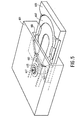
- the electro-optical device in accordance with the invention is very suitable for use in an optical disk-record player of the type as shown in Fig. 5.
- a player comprises a housing 601 with a front opening 603, through which a drawer 605 of a loading mechanism, for example as described in Netherlands Patent Application 8302129 (PHN.10.702) (herewith incorporated by reference), can be translated inwards and outwards, for transferring an optical disk to and removing it from the turntable of the electro-optical device in the housing 601.
- the drawing 605 comprises a transfer means 607 for supporting the disk.
- the transfer means 607 is vertically movable to enable the disk to be placed on or removed from the turntable when the drawer is in the fully retracted position.
- the vertical displacement of the transfer means 607 in the inward position of the drawer can be reduced substantially. It is even possible to mount the transfer means 607 immovably on the drawer 607.
- the tilting device 463 (see also Fig. 4) enables the turntable 455 to be moved so far downwards by means of the drive unit 501 that when the drawer 605 is slid in or slid out, the disk on the drawer 605 can be moved over the turntable 455 without touching it.
- the turntable 455 can simply be brought in the correct position by tilting it in an upward direction, so that the disk is automatically lifted off the transfer means 607 and positioned on the turntable 455.
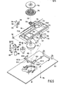
- Fig. 6 shows an electro-optical device constituting a fourth embodiment of the invention.
- This device comprises a frame 743 in which an electric motor 745 having a motor shaft 747 is secured.
- the motor shaft 747 carries a turntable 755 for an optical audio disc.
- the turntable 755 may be provided with an adapter 756 to render the turntable 755 suitable for supporting an optical video disc.
- a disc-pressure means 758 serves for axially clamping an audio or video disc onto the turntable.
- the electric motor 745 serves both for rotating and for supporting the turntable 755.
- the device comprises a subframe 753 and a slide 765 which can be translated relative to the subframe and which carries a focussing actuator 734 with an objective 715.
- the slide 765 By means of the slide 765 the objective 715 can be translated radially relative to the turntable 755 which is rotatable about an axis of rotation 757.
- the slide 765 is movable over a parallel guide means which comprises at least one flat guideway 773 on the subframe 763 and a lead screw 764 which is rotatably supported on the subframe 763 by suitable means.
- the slide 765 is in a slightly tilted position relative to the subframe 763 and the slide is also pressed against a guideway 773A, which extends parallel to the guideway 773, under the influence of gravity.
- the lead screw 764 is mechanically coupled to an electric motor 777 via a gear wheel 781 and a worm 783, which electric motor is secured to the subframe 763.
- the present construction enables the slide 765, which is mechanically coupled to the lead screw 764 by means not shown, to be moved exactly between a first position and a second position, the slide being situated nearer the turntable in the first position and being situated nearer an end portion 763A of the subframe 763 in the second position.
- the subframe 763 is pivotally mounted on the frame 743.
- a hinge construction 793 is provided on opposite sides of the subframe 763 and is secured to the subframe 763 and to the frame 743 by means of bolts 794 and 795 respectively.
- the hinge construction 793 comprises two plates 796 and 787 between which a double hinge 798 with two pivots is arranged.
- a lever element 802 is arranged between the frame 743 and the subframe 763, which element is pivotally supported in the frame and comprises two parallel lever arms 802A which engage in openings 804 in the subframe 763.
- the lever element 802 is pivotally connected to the subframe 763 via spindles, not shown, which extend through openings 806 in the lever arms and openings 807 in the subframe.
- the free ends of the lever arms 802A and the edge portions bounding the openings 804 may be given such shapes that by co-operation of said free ends with said edge portions the lever element 802 is pivotally connected to the subframe 763.
- a drive unit 801 which is secured to the frame 743 by means of a holder 803.
- the drive unit 801 comprises an electric motor 805 with a worm 807 which co-operates with a worm wheel 809 which is mounted for rotation in the holder 803 and to which a second worm 810 is secured.
- the worm 810 co-operates with a worm wheel 811 mounted on a lead screw 812.
- an element 813 which co-operates with the lever element 802 is movable in a vertical direction.
- the motor 805 When the motor 805 is energized the lever element 802 performs a rotary movement about its spindle ends 802B, causing the subframe to be tilted.
- the subframe 763, the pivotable lever element 802 and the hinge construction 793 constitute a special tilting device for tilting the objective supporting means during recording and/or reading of the tracks of an optical disc through a tilting angle which is related to the direction of the normal to the recording plane of the optical disc at the location of the intersection of the optical axis with the relevant plane.
- the tilting device together with the frame 743 constitutes a system resembling a four-bar linkage.
- the frame 743 and the subframe 763 form opposite sides of these linkages and the lever element 802, in particular the lever arms 802A, and the hinge constructions, in particular the double hinges 798, form the other two sides of the relevant linkages.
- the lever arms 802A and the double hinges 798 are arranged in pairs on opposite sides of the slide 765 in such a position relative to each other that their prolongations intersect and make an acute angle with each other.
- An advantage of this construction is that when the subframe 763 is tilted this subframe is also translated towards or away from the turntable 755. This enables the radial displacement of the objective 715 caused by the tilting movement of the subframe 763 to be automatically compensated for by mechanical means, thereby ensuring an even better correlation between the position of the objective and the tracks of the optical disc to be recorded or read. This readily results in a gain of time in locating specific positions on the disc, yielding very short access times.
- Embodiments other than those shown in the drawing are also possible.
- the turntable supporting means are movable about a fixed axis, as shown in Fig. 4.
- Tilting devices in which the pivotal axis is not stationary relative to the frame are also possible.
- a construction resembling a four-bar linkage may be very suitable for this purpose.
- the embodiments of the invention need not necessarily only be used in video-disk players.
- the electro-optical device in accordance with the invention is also suitable for use in audio-disk players and floppy-disk players.
Landscapes
- Optical Recording Or Reproduction (AREA)
- Moving Of The Head For Recording And Reproducing By Optical Means (AREA)
- Mechanical Optical Scanning Systems (AREA)
Applications Claiming Priority (2)
| Application Number | Priority Date | Filing Date | Title |
|---|---|---|---|
| NL8500592 | 1985-03-04 | ||
| NL8500592A NL8500592A (nl) | 1985-03-04 | 1985-03-04 | Electro-optische inrichting. |
Publications (2)
| Publication Number | Publication Date |
|---|---|
| EP0196691A1 true EP0196691A1 (fr) | 1986-10-08 |
| EP0196691B1 EP0196691B1 (fr) | 1990-07-11 |
Family
ID=19845611
Family Applications (1)
| Application Number | Title | Priority Date | Filing Date |
|---|---|---|---|
| EP86200309A Expired - Lifetime EP0196691B1 (fr) | 1985-03-04 | 1986-02-28 | Dispositif électro-optique |
Country Status (9)
| Country | Link |
|---|---|
| US (1) | US4694442A (fr) |
| EP (1) | EP0196691B1 (fr) |
| JP (2) | JPH0668846B2 (fr) |
| KR (1) | KR940001448B1 (fr) |
| CN (1) | CN1006100B (fr) |
| CA (1) | CA1253963A (fr) |
| DE (1) | DE3672512D1 (fr) |
| NL (1) | NL8500592A (fr) |
| SU (1) | SU1565356A3 (fr) |
Cited By (7)
| Publication number | Priority date | Publication date | Assignee | Title |
|---|---|---|---|---|
| EP0309854A2 (fr) * | 1987-09-30 | 1989-04-05 | Mannesmann Kienzle GmbH (HR B1220) | Enregistreur avec un boîtier plat |
| EP0329234A1 (fr) * | 1988-02-16 | 1989-08-23 | Koninklijke Philips Electronics N.V. | Dispositif électro-optique |
| EP0509531A2 (fr) * | 1991-04-19 | 1992-10-21 | Sony Corporation | Appareil d'enregistrement et/ou de reproduction de disques |
| EP0717400A1 (fr) * | 1994-12-15 | 1996-06-19 | Sony Corporation | Appareil de lecture de disque |
| EP0855709A1 (fr) * | 1997-01-23 | 1998-07-29 | Alps Electric Co., Ltd. | Appareil à disque |
| WO2000022616A1 (fr) * | 1998-10-09 | 2000-04-20 | Sony Corporation | Appareil d'enregistrement et/ou de reproduction |
| GB2356968B (en) * | 1999-09-29 | 2004-04-07 | Matsushita Electric Ind Co Ltd | Optical disk apparatus and method of installing its spindle motor |
Families Citing this family (14)
| Publication number | Priority date | Publication date | Assignee | Title |
|---|---|---|---|---|
| NL8602564A (nl) * | 1986-10-13 | 1988-05-02 | Philips Nv | Electro-optische aftastinrichting. |
| US5124973A (en) * | 1988-02-04 | 1992-06-23 | Pioneer Electronic Corporation | Tilt control mechanism |
| JPH0648568Y2 (ja) * | 1989-03-09 | 1994-12-12 | パイオニア株式会社 | 光ピックアップ装置のチルト機構 |
| US5150343A (en) * | 1989-07-19 | 1992-09-22 | Matsushita Electric Industrial Co., Ltd. | Miniaturized low-power-consumption optical head provided with a state transformation mechanism |
| US4980880A (en) * | 1989-11-06 | 1990-12-25 | Laser Magnetic Storage International Company | Method and apparatus for simultaneously reading both sides of an optical storage disk |
| US5218585A (en) * | 1990-10-01 | 1993-06-08 | International Business Machines Corporation | Phase shifting feedback control in an optical disk drive |
| US5815344A (en) * | 1992-02-17 | 1998-09-29 | Sony Corporation | Disc cartridge loading apparatus |
| JP2856008B2 (ja) * | 1992-10-30 | 1999-02-10 | 日本ビクター株式会社 | 光学式ディスク・プレーヤのチルトサーボ装置 |
| JPH06349218A (ja) * | 1993-04-12 | 1994-12-22 | Sony Corp | 光磁気ディスク装置 |
| JPH0855449A (ja) * | 1994-08-11 | 1996-02-27 | Sony Corp | ディスクドライブ装置 |
| EP0709834B1 (fr) * | 1994-10-31 | 2000-05-24 | Matsushita Electric Industrial Co., Ltd. | Capteur d'inclinaison, disque optique, et procédé de compensation d'inclinaison pour réaliser un contrôle de compensation d'inclinaison stable, et appareil les mettant en oeuvre |
| KR100195104B1 (ko) * | 1996-06-17 | 1999-06-15 | 윤종용 | 위상차 및 틸트 조정이 가능한 디스크플레이어 |
| KR100391043B1 (ko) * | 2001-01-15 | 2003-07-12 | 주식회사 Dm테크놀로지 | 디스크 플레이어의 틸트조정장치 |
| KR20070087629A (ko) * | 2004-11-30 | 2007-08-28 | 코닌클리케 필립스 일렉트로닉스 엔.브이. | 자동 디스크 기울기 교정 방법 및 장치 |
Citations (6)
| Publication number | Priority date | Publication date | Assignee | Title |
|---|---|---|---|---|
| FR2370340A1 (fr) * | 1976-11-04 | 1978-06-02 | Arvin Ind Inc | Mecanisme de commande du deplacement d'un transducteur d'enregistreur a disque, et cet enregistreur |
| EP0033047A1 (fr) * | 1980-01-24 | 1981-08-05 | Thomson-Csf | Equipage mobile d'un lecteur enregistreur de vidéodisque, et lecteur enregistreur de vidéodisque comprenant un tel équipage |
| GB2092812A (en) * | 1981-02-02 | 1982-08-18 | Dolby Ray Milton | Disc Reproducing System for Compensating Mechanical Imperfections |
| EP0074131A1 (fr) * | 1981-08-26 | 1983-03-16 | Koninklijke Philips Electronics N.V. | Dispositif à bras pivotant pour une unité de balayage optique |
| GB2143344A (en) * | 1983-04-27 | 1985-02-06 | Pioneer Electronic Corp | Optical information reading apparatus |
| GB2156069A (en) * | 1984-02-03 | 1985-10-02 | Pioneer Electronic Corp | Apparatus for reproducing recorded information |
Family Cites Families (8)
| Publication number | Priority date | Publication date | Assignee | Title |
|---|---|---|---|---|
| NL7703232A (nl) * | 1977-03-25 | 1978-09-27 | Philips Nv | Optische aftastinrichting. |
| JPS57199904A (en) * | 1981-06-03 | 1982-12-08 | Matsushita Electric Ind Co Ltd | Inclination controller |
| JPS5814332A (ja) * | 1981-07-16 | 1983-01-27 | Mitsubishi Electric Corp | 光学式情報再生装置 |
| JPS58170002U (ja) * | 1982-05-08 | 1983-11-12 | パイオニアビデオ株式会社 | デイスクプレ−ヤにおけるデイスク駆動部の調整機構 |
| JPS59146448A (ja) * | 1983-02-10 | 1984-08-22 | Sony Corp | 光学式デイスク・プレ−ヤ |
| JPS609018U (ja) * | 1983-06-24 | 1985-01-22 | パイオニア株式会社 | 光学式記録情報読取装置 |
| JPS60143447A (ja) * | 1983-12-30 | 1985-07-29 | Sony Corp | 光学式デイスク・プレ−ヤ |
| JPH0656667B2 (ja) * | 1985-01-09 | 1994-07-27 | 株式会社日立製作所 | 光学式記録再生装置 |
-
1985
- 1985-03-04 NL NL8500592A patent/NL8500592A/nl not_active Application Discontinuation
- 1985-06-26 US US06/749,149 patent/US4694442A/en not_active Expired - Lifetime
-
1986
- 1986-02-27 CA CA000502896A patent/CA1253963A/fr not_active Expired
- 1986-02-28 DE DE8686200309T patent/DE3672512D1/de not_active Expired - Lifetime
- 1986-02-28 EP EP86200309A patent/EP0196691B1/fr not_active Expired - Lifetime
- 1986-03-01 CN CN86102216A patent/CN1006100B/zh not_active Expired
- 1986-03-03 KR KR1019860001461A patent/KR940001448B1/ko not_active IP Right Cessation
- 1986-03-03 SU SU864027069A patent/SU1565356A3/ru active
- 1986-03-04 JP JP61045475A patent/JPH0668846B2/ja not_active Expired - Fee Related
-
1998
- 1998-06-17 JP JP10188176A patent/JP3059417B2/ja not_active Expired - Fee Related
Patent Citations (6)
| Publication number | Priority date | Publication date | Assignee | Title |
|---|---|---|---|---|
| FR2370340A1 (fr) * | 1976-11-04 | 1978-06-02 | Arvin Ind Inc | Mecanisme de commande du deplacement d'un transducteur d'enregistreur a disque, et cet enregistreur |
| EP0033047A1 (fr) * | 1980-01-24 | 1981-08-05 | Thomson-Csf | Equipage mobile d'un lecteur enregistreur de vidéodisque, et lecteur enregistreur de vidéodisque comprenant un tel équipage |
| GB2092812A (en) * | 1981-02-02 | 1982-08-18 | Dolby Ray Milton | Disc Reproducing System for Compensating Mechanical Imperfections |
| EP0074131A1 (fr) * | 1981-08-26 | 1983-03-16 | Koninklijke Philips Electronics N.V. | Dispositif à bras pivotant pour une unité de balayage optique |
| GB2143344A (en) * | 1983-04-27 | 1985-02-06 | Pioneer Electronic Corp | Optical information reading apparatus |
| GB2156069A (en) * | 1984-02-03 | 1985-10-02 | Pioneer Electronic Corp | Apparatus for reproducing recorded information |
Non-Patent Citations (4)
| Title |
|---|
| PATENTS ABSTRACTS OF JAPAN, vol. 7, no. 234 (P-230) [1379], 19th October 1983, page 3 P 230; & JP - A - 58 121 136 (FUOSUTAA DENKI K.K.) 19-07-1983 * |
| PATENTS ABSTRACTS OF JAPAN, vol. 7, no. 51 (P-179) [1196], 26th February 1983; & JP - A - 57 199 904 (MATSUSHITA DENKI SANGYO K.K.) 08-12-1982 * |
| PATENTS ABSTRACTS OF JAPAN, vol. 8, no. 141 (P-283) [1578], 30th June 1984, page 96 P 283; & JP - A - 59 40 327 (SONY K.K.) 06-03-1984 * |
| PATENTS ABSTRACTS OF JAPAN, vol. 9, no. 2 (P-325) [1725], 8th January 1985, page 101 P 325; & JP - A - 59 152 530 (SONY K.K.) 31-08-1984 * |
Cited By (12)
| Publication number | Priority date | Publication date | Assignee | Title |
|---|---|---|---|---|
| EP0309854A2 (fr) * | 1987-09-30 | 1989-04-05 | Mannesmann Kienzle GmbH (HR B1220) | Enregistreur avec un boîtier plat |
| EP0309854A3 (en) * | 1987-09-30 | 1989-05-10 | Mannesmann Kienzle Gmbh | Recorder with a flat housing |
| EP0329234A1 (fr) * | 1988-02-16 | 1989-08-23 | Koninklijke Philips Electronics N.V. | Dispositif électro-optique |
| EP0509531A2 (fr) * | 1991-04-19 | 1992-10-21 | Sony Corporation | Appareil d'enregistrement et/ou de reproduction de disques |
| EP0509531A3 (fr) * | 1991-04-19 | 1995-03-01 | Sony Corp | |
| US5416762A (en) * | 1991-04-19 | 1995-05-16 | Sony Corporation | Improved disc cartridge and recording and/or reproducing apparatus having means for positioning a turntable and disc cartridge support structure and means for reducing vibrations |
| EP0717400A1 (fr) * | 1994-12-15 | 1996-06-19 | Sony Corporation | Appareil de lecture de disque |
| EP0855709A1 (fr) * | 1997-01-23 | 1998-07-29 | Alps Electric Co., Ltd. | Appareil à disque |
| WO2000022616A1 (fr) * | 1998-10-09 | 2000-04-20 | Sony Corporation | Appareil d'enregistrement et/ou de reproduction |
| US6426925B1 (en) | 1998-10-09 | 2002-07-30 | Sony Corporation | Recording and/or reproducing apparatus with tilt adjustment mechanism |
| GB2356968B (en) * | 1999-09-29 | 2004-04-07 | Matsushita Electric Ind Co Ltd | Optical disk apparatus and method of installing its spindle motor |
| US6792614B1 (en) | 1999-09-29 | 2004-09-14 | Matsushita Electric Industrial Co., Ltd. | Optical disk apparatus and method of installing its spindle motor |
Also Published As
| Publication number | Publication date |
|---|---|
| JPH0668846B2 (ja) | 1994-08-31 |
| JPS61210531A (ja) | 1986-09-18 |
| CN1006100B (zh) | 1989-12-13 |
| DE3672512D1 (de) | 1990-08-16 |
| KR860007641A (ko) | 1986-10-15 |
| SU1565356A3 (ru) | 1990-05-15 |
| CN86102216A (zh) | 1986-09-03 |
| JP3059417B2 (ja) | 2000-07-04 |
| US4694442A (en) | 1987-09-15 |
| EP0196691B1 (fr) | 1990-07-11 |
| NL8500592A (nl) | 1986-10-01 |
| CA1253963A (fr) | 1989-05-09 |
| KR940001448B1 (ko) | 1994-02-23 |
| JPH1173665A (ja) | 1999-03-16 |
Similar Documents
| Publication | Publication Date | Title |
|---|---|---|
| EP0196691B1 (fr) | Dispositif électro-optique | |
| KR890000199B1 (ko) | 전자 광학장치 | |
| JPH0130229B2 (fr) | ||
| US5761182A (en) | Optical recording and reproducing apparatus | |
| EP0310156B1 (fr) | Lecteur de disques optiques | |
| US20020181386A1 (en) | Disk reproducing device | |
| EP0124353B1 (fr) | Tourne-disque optique | |
| US5025433A (en) | Electro-optical device | |
| US5263013A (en) | Apparatus for recording/reproducing of a double-sided optic disk | |
| KR100297773B1 (ko) | 대물렌즈 경사조정장치 | |
| EP1016082B1 (fr) | Appareil de reproduction de disque | |
| JPS6142741A (ja) | 光学デイスク装置の位置決め機構 | |
| JPS60160034A (ja) | 光学式デイスク・プレ−ヤ | |
| KR0176593B1 (ko) | 광 기록 재생 장치 | |
| JPS6122448A (ja) | 光学ヘツド位置決め機構 | |
| JPH0766554B2 (ja) | 記録情報読取装置 | |
| JPS6349864Y2 (fr) | ||
| KR0184746B1 (ko) | 광 픽업 구동장치 | |
| KR100200827B1 (ko) | 광 디스크의 정보 기록 장치 및 방법 | |
| JPH04222930A (ja) | 円盤状記録媒体の記録再生装置 | |
| KR0116636Y1 (ko) | 광픽업 구조체 | |
| JPH087309A (ja) | 対物レンズ駆動装置 | |
| JPH03142723A (ja) | チルトサーボ機構 | |
| JPH038123A (ja) | ピックアップ位置調整装置 | |
| JPH0684179A (ja) | 光記録再生装置 |
Legal Events
| Date | Code | Title | Description |
|---|---|---|---|
| PUAI | Public reference made under article 153(3) epc to a published international application that has entered the european phase |
Free format text: ORIGINAL CODE: 0009012 |
|
| AK | Designated contracting states |
Kind code of ref document: A1 Designated state(s): DE FR GB NL |
|
| 17P | Request for examination filed |
Effective date: 19870401 |
|
| 17Q | First examination report despatched |
Effective date: 19890406 |
|
| GRAA | (expected) grant |
Free format text: ORIGINAL CODE: 0009210 |
|
| AK | Designated contracting states |
Kind code of ref document: B1 Designated state(s): DE FR GB NL |
|
| PG25 | Lapsed in a contracting state [announced via postgrant information from national office to epo] |
Ref country code: NL Effective date: 19900711 |
|
| REF | Corresponds to: |
Ref document number: 3672512 Country of ref document: DE Date of ref document: 19900816 |
|
| ET | Fr: translation filed | ||
| NLV1 | Nl: lapsed or annulled due to failure to fulfill the requirements of art. 29p and 29m of the patents act | ||
| PLBE | No opposition filed within time limit |
Free format text: ORIGINAL CODE: 0009261 |
|
| STAA | Information on the status of an ep patent application or granted ep patent |
Free format text: STATUS: NO OPPOSITION FILED WITHIN TIME LIMIT |
|
| 26N | No opposition filed | ||
| REG | Reference to a national code |
Ref country code: FR Ref legal event code: CD |
|
| REG | Reference to a national code |
Ref country code: FR Ref legal event code: CD |
|
| REG | Reference to a national code |
Ref country code: GB Ref legal event code: IF02 |
|
| PGFP | Annual fee paid to national office [announced via postgrant information from national office to epo] |
Ref country code: FR Payment date: 20040226 Year of fee payment: 19 |
|
| PGFP | Annual fee paid to national office [announced via postgrant information from national office to epo] |
Ref country code: GB Payment date: 20040227 Year of fee payment: 19 |
|
| PGFP | Annual fee paid to national office [announced via postgrant information from national office to epo] |
Ref country code: DE Payment date: 20040415 Year of fee payment: 19 |
|
| PG25 | Lapsed in a contracting state [announced via postgrant information from national office to epo] |
Ref country code: GB Free format text: LAPSE BECAUSE OF NON-PAYMENT OF DUE FEES Effective date: 20050228 |
|
| PG25 | Lapsed in a contracting state [announced via postgrant information from national office to epo] |
Ref country code: DE Free format text: LAPSE BECAUSE OF NON-PAYMENT OF DUE FEES Effective date: 20050901 |
|
| GBPC | Gb: european patent ceased through non-payment of renewal fee |
Effective date: 20050228 |
|
| PG25 | Lapsed in a contracting state [announced via postgrant information from national office to epo] |
Ref country code: FR Free format text: LAPSE BECAUSE OF NON-PAYMENT OF DUE FEES Effective date: 20051031 |
|
| REG | Reference to a national code |
Ref country code: FR Ref legal event code: ST Effective date: 20051031 |