EP0195973B1 - Dispositif à chaînes centrifugées pour véhicules automobiles - Google Patents
Dispositif à chaînes centrifugées pour véhicules automobiles Download PDFInfo
- Publication number
- EP0195973B1 EP0195973B1 EP86103090A EP86103090A EP0195973B1 EP 0195973 B1 EP0195973 B1 EP 0195973B1 EP 86103090 A EP86103090 A EP 86103090A EP 86103090 A EP86103090 A EP 86103090A EP 0195973 B1 EP0195973 B1 EP 0195973B1
- Authority
- EP
- European Patent Office
- Prior art keywords
- unit
- flinger
- swivel
- wheel
- arm
- Prior art date
- Legal status (The legal status is an assumption and is not a legal conclusion. Google has not performed a legal analysis and makes no representation as to the accuracy of the status listed.)
- Expired - Lifetime
Links
- 239000002184 metal Substances 0.000 claims description 27
- 102000004315 Forkhead Transcription Factors Human genes 0.000 claims description 7
- 108090000852 Forkhead Transcription Factors Proteins 0.000 claims description 7
- 210000003746 feather Anatomy 0.000 claims description 6
- 239000013013 elastic material Substances 0.000 claims description 2
- 230000001747 exhibiting effect Effects 0.000 claims 3
- 239000000470 constituent Substances 0.000 claims 1
- 230000000284 resting effect Effects 0.000 claims 1
- 238000009434 installation Methods 0.000 description 8
- 239000000969 carrier Substances 0.000 description 5
- 238000011161 development Methods 0.000 description 4
- 230000018109 developmental process Effects 0.000 description 4
- 125000006850 spacer group Chemical group 0.000 description 4
- 238000005452 bending Methods 0.000 description 3
- 230000000694 effects Effects 0.000 description 3
- 210000003128 head Anatomy 0.000 description 3
- 238000004519 manufacturing process Methods 0.000 description 3
- 241000047428 Halter Species 0.000 description 2
- 230000003111 delayed effect Effects 0.000 description 2
- 238000013461 design Methods 0.000 description 2
- 238000012986 modification Methods 0.000 description 2
- 230000004048 modification Effects 0.000 description 2
- 238000003860 storage Methods 0.000 description 2
- 239000000725 suspension Substances 0.000 description 2
- 238000003466 welding Methods 0.000 description 2
- 229920001875 Ebonite Polymers 0.000 description 1
- 238000004026 adhesive bonding Methods 0.000 description 1
- 230000032683 aging Effects 0.000 description 1
- 238000005266 casting Methods 0.000 description 1
- 230000008021 deposition Effects 0.000 description 1
- 238000011835 investigation Methods 0.000 description 1
- 230000001788 irregular Effects 0.000 description 1
- 230000000149 penetrating effect Effects 0.000 description 1
- 239000002984 plastic foam Substances 0.000 description 1
- 238000009420 retrofitting Methods 0.000 description 1
- 239000007787 solid Substances 0.000 description 1
- 239000003381 stabilizer Substances 0.000 description 1
- 230000035882 stress Effects 0.000 description 1
- 230000001629 suppression Effects 0.000 description 1
- 238000012360 testing method Methods 0.000 description 1
Images


Classifications
-
- B—PERFORMING OPERATIONS; TRANSPORTING
- B60—VEHICLES IN GENERAL
- B60B—VEHICLE WHEELS; CASTORS; AXLES FOR WHEELS OR CASTORS; INCREASING WHEEL ADHESION
- B60B39/00—Increasing wheel adhesion
- B60B39/003—Vehicle mounted non-skid chains actuated by centrifugal force
-
- Y—GENERAL TAGGING OF NEW TECHNOLOGICAL DEVELOPMENTS; GENERAL TAGGING OF CROSS-SECTIONAL TECHNOLOGIES SPANNING OVER SEVERAL SECTIONS OF THE IPC; TECHNICAL SUBJECTS COVERED BY FORMER USPC CROSS-REFERENCE ART COLLECTIONS [XRACs] AND DIGESTS
- Y10—TECHNICAL SUBJECTS COVERED BY FORMER USPC
- Y10T—TECHNICAL SUBJECTS COVERED BY FORMER US CLASSIFICATION
- Y10T152/00—Resilient tires and wheels
- Y10T152/10—Tires, resilient
- Y10T152/10279—Cushion
Definitions
- the invention relates to a sling chain unit for motor vehicles, which has a holder which is fastened on one side to the motor vehicle by means of two brackets which can be mounted at a distance from the vehicle, and an anti-skid device carried by the latter with a centrifugal wheel which carries a number of chain strands, is rotatably arranged on a swivel arm of the holder and by means of a Swivel drive can be pivoted from a rest position into an operating position in which the centrifugal wheel lies against the inside wall of the vehicle wheel to be taken along by a vehicle wheel under pre-tension.
- Slingshot chain units have been described many times in the prior art. They form a winter driving protection that is essentially used in commercial vehicles, which can be switched on by the driver if necessary and which significantly improves the traction between the drive wheels and the road.
- US-A 2 543 876 discloses a sling chain unit with the features mentioned in the introduction and a rotary piston drive for the swivel arm. This known device is held with a fixed bracket that engages the spring clips and directly on the vehicle axle.
- a switchable winter driving protection according to the addressed prior art or also according to modifications that do not work with sling chains is particularly useful for commercial vehicles, because their area of activity regularly extends over snowy and snow-free areas in winter and the operation with conventional snow chains requires a very frequent assembly and disassembly, which the Transport times extended.
- brackets connecting the centrifugal wheel to the vehicle not only have to be designed differently from manufacturer to manufacturer, but in most cases also from vehicle type to vehicle type of each manufacturer, and in each individual case still have two mirror images Variants for mounting on the right and left side of the vehicle are required.
- This almost inexhaustible variety of types initially results in considerable development costs, manufacturing costs and storage costs. To make matters worse, there are many assembly instructions to be observed and that the workshops available for retrofitting cannot gain enough experience due to the variety of types, so that the installation of the winter driving protection is unnecessarily expensive.
- Slingshot chain units of the type mentioned also only work properly under the various conditions that occur when the slingshot wheel occupies a precisely defined position on the vehicle wheel in its operating position. Deviations from the target position due to external circumstances, e.g. after changing the tire type, wear-causing fluttering phenomena of the centrifugal wheel lead to irregular throwing of the chains into the gap between the vehicle wheel and the road surface and, in the worst case, permanent deposition of the centrifugal wheel by bending the holder of the centrifugal chain unit.
- the object of the invention is also to provide a sling chain unit which makes fine adjustment and readjustment of the centrifugal wheel effortlessly possible during or after the installation of the sling chain unit.
- the invention is also based on the object to significantly reduce the tendency of the centrifugal wheel to flutter.
- the center of the plane of rotation of the centrifugal wheel preferably lies at a distance below the center of an adjustable ball joint, which according to the invention is arranged between the swivel arm and the centrifugal wheel.
- the ball joint has a split metal bushing and a ball element arranged in its shell-shaped inner bore, which has a bore passing through its center for receiving a bolt, which in turn carries the centrifugal wheel and that the split bushing in a Diameter-variable bore is attached to or in the swivel arm and that the bolt has a collar that abuts the ball element.
- the centrifugal wheel is movably mounted on the swivel arm against the tension of a spring element
- the spring element can connect the swivel arm to a lever
- the centrifugal wheel can be rotatably mounted at the free end of this lever and the free end of the lever itself from which the centrifugal wheel driving vehicle wheel are located beyond the swivel arm in its operating position.
- centrifugal wheel can be fastened to the lever in an adjustable manner with respect to the predefined pivot plane, and a ball joint, which can be locked by means of a clamping device, can be provided at the free end of the lever / housing for the movable arrangement of the centrifugal wheel with respect to the predefined plane.
- the tolerance range is expanded, within which the centrifugal wheel resiliently trailing according to the invention prevents fluttering. This widening of the tolerance range is particularly helpful in cases where, for example, the tire type of the respective vehicle is changed.
- the anti-skid device for a vehicle wheel 10 shown in particular in FIGS. 2 and 3, has, in a known manner, a number of chain strands 20 which are attached at one end to a centrifugal wheel 22.
- the chain strands protrude from the centrifugal force approximately radially and distributed on a conical jacket from the centrifugal wheel. Due to the arrangement and orientation of the centrifugal wheel with respect to the vehicle wheel 10 and the surface of the road 11, the chain strands are successively thrown into the gap 16 located in the direction of travel between the rotating vehicle wheel 10 and the road 11 and overrun by the vehicle wheel.
- the rotation of the centrifugal wheel 22 is produced in a known manner in that the centrifugal wheel is pressed against the vehicle interior side of the tire of the vehicle wheel 10 and is set in rotation by the tire as a result of this frictional engagement as long as the vehicle wheel 10 rotates itself.
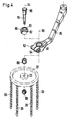
- the centrifugal wheel 22 is fastened to the free end 25 of a swivel arm 26 by means of a rotary bearing 23 indicated in FIG. 1 about an axis of rotation 24.
- the swivel arm 26 is in turn pivotally mounted on a support element 30 about a swivel axis 27, which in turn is connected to the vehicle in a manner to be described.
- the pivotable mounting of the centrifugal wheel 22 on the one hand enables easy generation of the pretension between the centrifugal wheel 22 and the vehicle wheel 10 and serves primarily to move the centrifugal wheel from the operating position shown in FIGS. 2 and 3 into a z. 1 of DE-OS 31 00 975 removable rest position, in which the chain strands hang freely from the centrifugal wheel 22 down, can no longer touch the road 11 and in which the centrifugal wheel 22 out of contact with the Vehicle wheel 10 stands.
- a pneumatic cylinder 28 with a piston rod 29 is provided as the pivot drive for the pivot arm 26.
- the pneumatic cylinder 28 is fastened to the support element 30 by means of screws (not shown) and by means of bores 31 (FIG. 1).
- the piston rod 29, the relative position and orientation of which can be seen in particular in FIG. 2, has at its free end a ball joint 32 which serves to connect the piston rod 29 to the swivel arm 26 at a point between the axes 24 and 27.
- Fig. 2 shows the extended position of the piston rod 29, which corresponds to the operating position of the swivel arm 26 or the centrifugal wheel 22.
- the centrifugal wheel 22 moves to the right away from the vehicle wheel 10 when viewing FIG. 3. 2 and 3, the inclination of the pivot axis 27 causes the centrifugal wheel 22 to move upwards at the same time.
- a multi-element holder 40 is used to fasten the anti-skid device described so far to the vehicle. It ensures that the centrifugal wheel 22 is always correctly aligned with the vehicle wheel 10 in its operating position, regardless of the loading condition of the vehicle. This results in a requirement that the holder 40 should be connected to the unsprung mass of the vehicle, for example, according to FIGS. 2 and 3, on a holding plate 33 for the spring of the vehicle, not shown, or on one with the axle 12 of the vehicle wheel 10 connected holder for a stabilizer or the like. Or independently of this directly on the axle 12.
- an installation situation is specified in which the holding plate 33 for the vehicle spring (not shown) is fixedly connected in a conventional manner to the axle 12 of the vehicle wheel 10 by means of bolts 34.
- a total of four bolts 34 are provided, two of which are vertically aligned in the forward direction of travel (arrow 14) and the other two bolts 34 are behind the axis 12.
- the holder 40 On the axis side, the holder 40 has two identical carriers 42. Each carrier 42 is provided with a first bore 44, which serves to receive one bolt 34 each, and whose central axis 45 thus lies in the longitudinal axis of the respective bolt 34.
- Fig. 2 shows that the two bolts 34 used to fix the carrier 42 are longer than the other two bolts 34 and that 42 spacers 46 can be provided below the holding plate 33 for the vertical alignment of the carrier.
- each carrier 42 Spaced from the bore 44, each carrier 42 has a holder 43 in the form of an eye, a bushing or the like with a second bore 48 running transversely to the first bore 44, the axis 50 of which in the exemplary embodiment runs perpendicular to the central axis 45. 1 and 2, the carriers 42 are fastened in such a way that their bores 48 are aligned.
- the two second bores 48 of the carrier 42 are penetrated by a support bolt 60, which is cylindrical in the exemplary embodiment and which is firmly connected to the two carriers 42 when the holder 40 is assembled.
- This connection can be made in any known manner, for example by welding, pinning or gluing.
- a clamp attachment is provided.
- the bore 48 of each carrier 42 is part of a slotted eye at the free end of the carrier 42, which can be clamped by means of a clamping bolt 52 and a nut 54 for the non-positive fixing of the supporting bolt 60.
- Equally equivalent to the embodiment of the holder 40 described so far would be a one-piece support provided with two bores 44, on which the support bolt 60 would be can be fixed that it is exposed between its ends and / or at least one of its ends for the connection of a further element (z. B. 62) of the holder 40.
- the following description shows that the universality of a holder with two separate carriers 42 is greater and therefore should be preferred to a one-piece carrier if it were equipped with elongated holes instead of cylindrical bores 44.
- the support pin 60 of the holder 40 serves to hold a thru axle 62 which has a pivot bearing 64 at one end.
- this swivel bearing consists of a clamping eye attached to one end of the plug-in axis 62, through which the supporting bolt 60 can be pushed and which can be tightened by means of a clamping bolt 52 and a nut (not shown).
- a clamping bolt 52 and a nut not shown.
- Fig. 1 clearly shows that the central axis 63 of the plug axis 62 extends perpendicular to the axis 50 of the support pin 60 and bores 48. Furthermore, it can be seen that the plug-in axis 62 can be connected to the support bolt 60 at different points between the two supports 42 or outside of these supports. This results in a first degree of freedom for the assembly of the anti-skid device. The second degree of freedom results from the pivotability of the plug-in axle 62 relative to the support bolt 60 before its mutual locking / clamping.
- the support element 30 already mentioned above has a fork 36 at one end for the pivotable mounting of the pivot arm 26 about the axis 27, as shown in particular in FIG. 1. Between this fork and the plate-shaped other end of the support element 30, which is provided with the bores 31, there is an eye 38 for receiving the or a plug-in axis (z. B. 62).
- the axis 39 of the eye 38 runs parallel to the pivot axis 27, and the plane receiving the two axes 27, 39 in the exemplary embodiment runs perpendicular to the main plane of the support element 30, in which the end of the support element having the bores 31 lies.
- the support element 30 can be fastened directly (not shown) or indirectly (exemplary embodiment) to the thru axle 62.
- the outer diameters of support bolts 60, thru axle 62 and any further thru axles 66 in the exemplary embodiment are identical to one another, and these parts of the holder are preferably designed as tubes. Accordingly, the receptacles (sockets, eyes, etc.) for these parts are provided with the same inner diameters, which are adapted to the mentioned outer diameter.
- a cross connector 70 is provided for connecting a further plug-in axis 66 to the plug-in axis 62, which cross connector can be pivoted and axially displaced on the plug-in axis.
- the cross connector 70 essentially consists of two eyes 72, 74 fastened to one another with inner diameters corresponding to the outer diameter of the thru axles. These two eyes 72, 74 and the other eyes mentioned so far have the shape of sufficiently thick-walled bushes in the exemplary embodiment.
- the axes of the eyes 72, 74 run at a distance from one another and on the one hand in the direction of the central axis 63 of the plug-in axis 62 and on the other hand in the direction of the axis 39 of the eye 38 of the support element 30.
- the connection of the eyes 38 and 74 serves the further purpose Thru axle 66.
- the support element 30 can be attached at any distance from the eye 74 of the cross connector 70 and in any angular position with respect to the axis 39 on the further plug-in axis 66, whereby two additional degrees of freedom, that is a total of six degrees of freedom for the assembly of the anti-skid device in the case of the exemplary embodiment. Finally, since the support element 30 can be fastened not only in the position shown, but also with its surface visible in FIG. 1 facing downward on the plug-in axle 66, the support element 30 can be in an almost unlimited number of spatial positions in the area between the axis 12, the road 11 and the vehicle wheel 10 are arranged. This will achieve the desired success, i.e. H. So the usability of identical holder elements on opposite sides of the vehicle is reached.
- the swivel arm 26 which is also an element of the holder, is formed symmetrically on both sides of the plane receiving the axes 24 and 27, as is the case in the exemplary embodiment. then the swivel arm can be used unchanged on both sides of the vehicle.
- a modified embodiment of the arrangement of the supporting bolt 60 on the vehicle is not shown.
- This modification consists in that the axis 50 passing through the two brackets 43 is inclined to that straight line which is perpendicular to at least one of the further axes 45 and connects these two axes 45.
- This modified arrangement z. B. in that the two carriers 42 are of different lengths, so that the clear distance between the center of the bore 48 and the center of the associated bore 44th of a carrier 42 is greater than the corresponding distance of the second carrier.
- a ball joint is used to fasten the centrifugal wheel 22 to the swivel arm 26: It consists of a split metal bushing 80 which is inserted into a bore 81 at the free end of the swivel arm 26 and there by means of a clamping bolt 52 and a nut 54 can be clamped, since the free end of the swivel arm 26 is slotted from its end face into the region of the bore 81.
- the socket 80 has a shell-shaped or spherical inner surface in which a spherical element 82 rests.
- the ball element 82 has a through bore 83 penetrating its center. If the ball joint consisting of bushing 80 and ball element 82 is inserted into the bore 81 of the swivel arm 26, a bolt 84 provided with a collar 85 is inserted through the bore 83 of the ball element 82 from the top of the swivel arm 26. A spacer bush 86 and then the centrifugal wheel 22 with its rotary bearing 23 are then pushed onto the bolt from below. Finally, the bolt 84, the ball joint, the spacer bush 86 and the centrifugal wheel 22 are firmly clamped together by means of a nut 88 screwed onto the bolt 84. The pivot bearing 23 ensures that the centrifugal wheel 22 can rotate freely.
- the axis of rotation 24 of the centrifugal wheel 22 then receives its desired spatial position, which usually does not coincide with the axis 90 of the bore 81 in the swivel arm 26. Finally, the nut 54 is tightened on the clamping bolt 52, thereby fixing the set position of the axis of rotation 24. An adjustment of the position of the axis of rotation 24 is possible at any time after loosening the clamping bolt 52.
- the ball joint 80, 82 does not necessarily have to be mounted in the bore 81 of the swivel arm 26, but that the ball joint can also be provided on or in an extension of the swivel arm, which in turn is movable and / or opposite the swivel arm is adjustable.
- the receptacle for the ball joint 80, 82 is not simply a bore of the swivel arm 26; rather, two parallel openings 81 and 89 connected by a slot 87 are provided in this. In the area of the slot 87, a clamping bolt 52 extends through the opposite sections of the swivel arm 26 which are separate from the slot 87.
- the entire area of the swivel arm 26 receiving the ball joint 80, 82 is provided with a continuous wall, which facilitates a distortion-free casting of the swivel arm 26.
- the centrifugal wheel 22 is fastened to the free end 25 of the swivel arm 26 with the intermediary of a centrifugal wheel carrier 100.
- This in turn is mounted on the support element 30 so as to be rotatable about the pivot axis 27, and can be pivoted from the operating position of the centrifugal wheel into the rest position in the manner already described.
- the centrifugal wheel carrier 100 has a housing 110 which is penetrated by two parallel bores 112, 114.
- a rubber-metal bushing 116 is pressed into the bore 112. It is non-rotatable with respect to the housing 110 under all usual operating situations.
- the rubber-metal bushing 116 has an axially continuous groove 118 for a feather key 120 in an axial bore 117.
- a continuation of the groove 118 is provided in the form of a groove 122 in a bore 124 in the free end 25 of the swivel arm 26.
- a collar bolt 126 is used to fasten the housing 110 to the swivel arm 26. It also has a groove 128 for the feather key 120 and is seen in the exemplary embodiment in the manner shown in FIG. 7 from bottom to top through the central bore of a disk 130 through which Axial bore 117 of the rubber-metal bush 116 and the bore 124 of the swivel arm 26 passed through.
- a stop nut 132 is used to tighten the collar bolt 126 and thus to mount the housing 110 on the swivel arm 26.
- the key 120 inserted into the collar bolt before it is inserted ensures that the inside of the rubber-metal bushing 116 cannot move relative to the collar bolt 126 and the swivel arm 26.
- the axial rubber projections which may form when the rubber-metal bushing 116 is pressed into the housing 110 are formed on the two axial ends of the bore 112 to increase the press-in force by means of the disk 130 and by means of the lower surface of the swivel arm 26 Let it push back inside the rubber-metal bush 116.
- the housing 110 fastened to the swivel arm 26 in the manner described can now be pivoted elastically or resiliently about the axis 113 of the bore 112 due to the action of the rubber within the rubber-metal bush 116.
- the same mobility can be achieved in an equivalent manner in that the spring element 116 is either pressed with its outer bush into the correspondingly enlarged bore 124 of the swivel arm or is fastened in another way to the free end 25 and that the bore 112 of the housing 110 to the dimension of Collar bolt 126 is reduced and provided with a groove to be aligned with groove 118.
- the centrifugal wheel 22 with the pivot bearing 23, which is only indicated, can be fastened to the housing 110 by means of a bolt which penetrates the bore 114 and which also penetrates the pivot bearing 23.
- the attachment already described above with reference to FIG. 4 is preferred, which makes it possible here to incline the rotational plane of the centrifugal wheel 22 relative to the pivot plane of the housing 114 about the axis 113.
- the split bushing 80 is inserted into the bore 114 of the housing 110.
- it has a bowl-shaped, continuous inner bore for receiving the axially pierced ball element 82.
- the bolt 84 provided with a collar passes through the axial bore of the ball element 82, the spacer bush 86 provided below the housing 110 and the pivot bearing 23 of the centrifugal wheel 22 and is fixed by means of the nut 88.
- the housing 110 is continuously slotted in the area of its bore 114 from the outside to the bore. Furthermore, a clamping bolt 52. And a nut 54 screwed onto its end are provided.
- the clamping bolt passes through an additional bore in the housing 110 in the area of the slot mentioned, so that the split bushing 80 can be fixed within the bore 114 by means of the clamping bolt 52 and the nut 54.
- the bolt 84 can be tilted to a certain extent together with the ball element 82 before the clamping bolt 52 is tightened, so that the longitudinal axis of the bolt 84 is not necessarily parallel to the axis 113.
- the cup-shaped inner bore of the split bushing 80 and the outer surface of the ball element 82 are rough. so that a secure positioning of the bolt 84 within the housing 110 is ensured even when impacted.
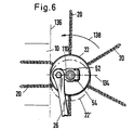
- the connecting line 134 of the center points of the bores 112, 114 of the housing 110 is in the operating position of the swivel arm 26, as shown in FIG. 6, approximately perpendicular to the projection line 136 of the inner surface of the vehicle wheel 10.
- the plane of rotation of the centrifugal wheel 22 is parallel below in its basic position the pivoting plane of the centrifugal wheel carrier 100.
- the axis of the bolt 84 runs parallel to the axis 113 of the bore 112.
- the bore 112 of the housing 110 and thus also the free end 25 of the pivot arm 26 are located in the area between the inner surface (projection line 136) of the vehicle wheel 10 and the bore 114 of the housing 110. In other words, the housing 110 projects away from the vehicle wheel 10 as seen from the swivel arm 26.
- the arrow 138 in FIG. 6 indicates the direction of rotation of the centrifugal wheel 22 when the vehicle is moving forward.
- the dash-dotted circular line 22 'in Fig. 6 shows. that the centrifugal wheel dodges to the rear. when the chain strands 20 are released from the vehicle wheel 10 with a delay.
- the swivel arm 26 is pressed against the vehicle wheel 10 with an additional force component due to the selected arrangement with such a delayed release.
- the centrifugal wheel 22 returns to the zero position which is shown in FIG. 6 by a solid circular line.
- centrifugal wheel carrier 100 is aligned with the swivel arm 26 and the two above-mentioned grooves 122, 128 are aligned with one another in such a way that the connecting line 134 is cut by a vertical line starting from the center line of the axis 12.
- the free end 25 of the swivel arm 26 is fork-shaped.
- the end of the housing 110 which receives the rubber-metal bush 116 then lies in the intermediate space between the two fork elements. It is understood that in this case the bore 124 penetrates both elements of the fork and that the groove 122 also passes through both elements.
- Fiq. 8 instead of a rubber-metal bushing, a different type of suspension system is provided for mounting the centrifugal wheel 22 on the swivel arm 26.
- the swivel arm head of the swivel arm 26 is designed as a fork head 91 in such a way that the two fork arms 104 lie vertically one above the other.
- Each fork arm 104 has a vertical bore 92; the through holes 92 are aligned.
- Two webs 105 protruding from the rear wall 106 between the fork arms 104 on a vertical side of the fork head in each case enclose the part 108 of the fitting 96 lying against the rear wall 106 and thus prevent the fitting 96 from being pushed out of the area between the fork arms 104 .
- the fitting 96 used does not extend completely between the fork arms 104 into the area of the through bores 92 thereof. In this area there remains a space which accommodates one Compensation lever 97 is used.
- the leveling lever 97 is shaped so that it can be inserted between the fork arms 104 in a substantially suitable manner.
- the compensating lever 97 has a bore 98 which, when inserted between the fork arms 104, is aligned with the through holes 92. In this position, the compensating lever 97 is pivotably mounted on the fork arms 104 by means of a short shaft 94 which penetrates the through holes 92 and the bore 98.
- the shaft 94 is guided in two bushes 93, each received in a through-bore 92, the collars of which each abut the associated inner surface of a fork arm 104.
- a horizontal bore 101 extends through the compensating lever 97 and thereby intersects the bore 98. In the installed state of the compensating lever 97, it is aligned with a corresponding bore 95 of the shaft 94. A notch pin 99 is received in the bores 101 and 95 and connects the compensating lever 97 to the shaft 94 to rotate together.
- the compensating lever 97 On its side facing the fitting 96 in the installed state, the compensating lever 97 carries two corner projections 102 which engage in a form-fitting manner in corner grooves 103 of the fitting 96.
- the compensating lever also carries, on an extension projecting laterally in the installed state between the fork arms 104, a clamping sleeve 107, which forms an opening 81 of the type already described for clamping a ball joint 80, 82.
- the compensating lever 97 carries, by means of the clamping sleeve 107, the centrifugal wheel 22 which is fastened to the ball joint 80, 82 in the manner described earlier.
- the compensating lever 97 pivots with respect to the fork head 91, deforming the shaped part 96.
- the elasticity of the shaped piece 96 resiliently absorbs the deflection and subsequently resets the compensating lever 97.
- the engagement of the corner projections 102 with the corner grooves 103 and the seat of the fitting 96 between the webs 105 prevent the fitting 96 from being pushed out between the fork arms 104.
- This resilient mounting of the compensation lever 97 holds the centrifugal wheel 22 elastically against the vehicle tire and brings about effective flutter suppression even over long periods of time.
- the symmetrical mounting of the compensating lever 97 on the shaped piece 96 has the effect that a deflection in each of the two pivoting directions is equally resiliently intercepted.
- the symmetry of the components allows assembly on both sides of the vehicle.
Landscapes
- Engineering & Computer Science (AREA)
- Mechanical Engineering (AREA)
- Vehicle Body Suspensions (AREA)
Claims (47)
Priority Applications (1)
| Application Number | Priority Date | Filing Date | Title |
|---|---|---|---|
| AT86103090T ATE49538T1 (de) | 1985-03-14 | 1986-03-07 | Schleuderkettenaggregat fuer kraftfahrzeuge. |
Applications Claiming Priority (6)
| Application Number | Priority Date | Filing Date | Title |
|---|---|---|---|
| DE3509062 | 1985-03-14 | ||
| DE3509063 | 1985-03-14 | ||
| DE19853509061 DE3509061A1 (de) | 1985-03-14 | 1985-03-14 | Halter fuer eine gleitschutzvorrichtung eines fahrzeugrades |
| DE3509061 | 1985-03-14 | ||
| DE19853509062 DE3509062A1 (de) | 1985-03-14 | 1985-03-14 | Schleuderkettenaggregat fuer kraftfahrzeuge |
| DE19853509063 DE3509063A1 (de) | 1985-03-14 | 1985-03-14 | Vorrichtung zum positionieren des schleuderrades eines schleuderkettenaggregates fuer kraftfahrzeuge |
Publications (2)
| Publication Number | Publication Date |
|---|---|
| EP0195973A1 EP0195973A1 (fr) | 1986-10-01 |
| EP0195973B1 true EP0195973B1 (fr) | 1990-01-17 |
Family
ID=27192889
Family Applications (1)
| Application Number | Title | Priority Date | Filing Date |
|---|---|---|---|
| EP86103090A Expired - Lifetime EP0195973B1 (fr) | 1985-03-14 | 1986-03-07 | Dispositif à chaînes centrifugées pour véhicules automobiles |
Country Status (4)
| Country | Link |
|---|---|
| US (1) | US4745993A (fr) |
| EP (1) | EP0195973B1 (fr) |
| CA (1) | CA1272110A (fr) |
| DE (1) | DE3668284D1 (fr) |
Families Citing this family (12)
| Publication number | Priority date | Publication date | Assignee | Title |
|---|---|---|---|---|
| EP0278899A1 (fr) * | 1987-01-21 | 1988-08-17 | Beka St-Aubin SA | Dispositif de fixation d'un dispositif de chaîne à neige auxiliaire pour véhicule routier |
| EP0334810B1 (fr) * | 1988-03-25 | 1993-04-21 | Beka St-Aubin SA | Dispositif de positionnement et de fixation d'un dispositif de chaîne à neige auxiliaire pour véhicule routier |
| SE467456B (sv) * | 1988-10-20 | 1992-07-20 | Onspot Ab | Armlagring vid slirskydd |
| DE4215370C2 (de) * | 1992-05-08 | 1994-08-18 | Rud Ketten Rieger & Dietz | Gleitschutzvorrichtung für Kraftfahrzeuge |
| US6651783B1 (en) * | 2000-08-28 | 2003-11-25 | John H. Atkinson, Jr. | Adjustable mounting assembly for a rapidly-deployable ice chain system for wheeled vehicles |
| WO2005070737A1 (fr) * | 2004-01-13 | 2005-08-04 | Smith Fred P | Systeme d'asservissement electrique a couple limite permettant de deployer pour un vehicule un systeme de traction par chenille sur la neige |
| US7118130B2 (en) * | 2004-01-23 | 2006-10-10 | Onspot Of North America, Inc. | Anti-skid tire chain device |
| US7766387B1 (en) * | 2007-08-02 | 2010-08-03 | Onspot Of North America, Inc. | Anti-skid tire chain device |
| DE202007011293U1 (de) * | 2007-08-13 | 2007-10-18 | Karl Hildebrand Gmbh | Lageranordnung für ein drehbares Halteelement |
| US20110146866A1 (en) * | 2009-12-19 | 2011-06-23 | Samad Jafari Valilou | Automatic tire chain system |
| EP3296125B1 (fr) * | 2016-09-15 | 2019-05-15 | VBG Group AB (Publ) | Dispositif antidérapant doté d'un élément protecteur |
| US10675914B2 (en) * | 2017-12-20 | 2020-06-09 | Dusawn Holdings LLC | Tire chains apparatus |
Family Cites Families (11)
| Publication number | Priority date | Publication date | Assignee | Title |
|---|---|---|---|---|
| GB110674A (en) * | 1917-01-22 | 1917-11-01 | Harold Thorne | Improvements in Anti-skid Devices for Automobiles and the like. |
| US2283948A (en) * | 1941-04-09 | 1942-05-26 | Herbert N Ridgway | Automobile traction device |
| US2442322A (en) * | 1945-01-29 | 1948-05-25 | Frank J Daley | Antiskid device |
| US2543876A (en) * | 1949-04-23 | 1951-03-06 | William P C Smith | Hydraulic power unit with fixed piston for producing oscillating motion |
| US2747691A (en) * | 1952-11-05 | 1956-05-29 | Frank J Lakey | Retractable traction and antiskid device for vehicles |
| US2771161A (en) * | 1954-12-13 | 1956-11-20 | Jesionowski John | Anti-skid apparatus |
| US2865471A (en) * | 1956-12-26 | 1958-12-23 | Francis P Chaussee | Anti-skid device for vehicles |
| US2886138A (en) * | 1957-07-01 | 1959-05-12 | Abrom D Bruner | Automatic traction device for vehicles |
| SE8000281L (sv) * | 1980-01-14 | 1981-07-15 | Toernebaeck Goeran | Slirskydd for motorfordon |
| FR2548746B1 (fr) * | 1983-07-04 | 1986-05-16 | Thomson Brandt | Articulation a rotule immobilisable a l'aide d'un seul element de blocage |
| EP0151098B1 (fr) * | 1984-01-17 | 1991-10-23 | Törnebäcks Verkstäder Kb | Dispositif antidérapant télécommandé |
-
1986
- 1986-03-07 EP EP86103090A patent/EP0195973B1/fr not_active Expired - Lifetime
- 1986-03-07 DE DE8686103090T patent/DE3668284D1/de not_active Expired - Lifetime
- 1986-03-12 US US06/838,664 patent/US4745993A/en not_active Expired - Fee Related
- 1986-03-14 CA CA000504116A patent/CA1272110A/fr not_active Expired - Lifetime
Also Published As
| Publication number | Publication date |
|---|---|
| US4745993A (en) | 1988-05-24 |
| EP0195973A1 (fr) | 1986-10-01 |
| DE3668284D1 (de) | 1990-02-22 |
| CA1272110A (fr) | 1990-07-31 |
Similar Documents
| Publication | Publication Date | Title |
|---|---|---|
| DE3212842C2 (fr) | ||
| DE3781481T2 (de) | Sturzeinstellung. | |
| DE4115110C2 (de) | Vorrichtung zum werksseitigen Voreinstellen von Fahrzeugrädern | |
| DE69213172T2 (de) | Justiervorrichtung für Fahrzeugaufhängungen | |
| DE10257198A1 (de) | Vorrichtung zum Einstellen von Sturz und Nachlauf eines Rades | |
| EP0195973B1 (fr) | Dispositif à chaînes centrifugées pour véhicules automobiles | |
| DE69319045T2 (de) | Fahrzeugaufhängung mit Schwenkarm und Verfahren zum Befestigen einer Antriebsachse an einem Schwenkarm | |
| DE4001597C2 (de) | Sturzeinstellvorrichtung | |
| DE69719923T2 (de) | Förderer | |
| EP2990240B1 (fr) | Kit de montage d'un ressort sur la suspension de roue unique d'un vehicule automobile | |
| DE3630531A1 (de) | Verfahren zur einstellung des sturzes eines rads | |
| DE1292524B (de) | Parkeinrichtung fuer Kraftfahrzeuge | |
| DE102018120916A1 (de) | Integriertes Lenkgabelgelenk und Federteller für Aufhängungssysteme | |
| DE3232410A1 (de) | Radaufhaengung fuer fahrzeuge | |
| DE69012314T2 (de) | Aufhängungssystem für Tiefladeanhänger. | |
| DE69519673T2 (de) | Dämpfungsvorrichtung für kraftfahrzeugstabilisatoren und verfahren zu ihrer befestigung | |
| DE4309561C2 (de) | Gabelhubwagen mit einem Antriebsrad und seitlichen Stützrädern | |
| DE19636719A1 (de) | Lenkbare Starrachse für ein Kraftfahrzeug | |
| DE4244140C2 (de) | Schwenklager | |
| EP0376428A1 (fr) | Système antidérapant pour roues de véhicule | |
| EP0645216B1 (fr) | Compresseur de ressort pour ressorts de suspension MacPherson | |
| DE3200836C2 (de) | Vorrichtung zum Einstellen der Achse eines Gelenkes zur schwenkfähigen Aufhängung eines Radführungslenkers am Aufbau oder an einem separaten Achsträger eines Kraftfahrzeuges | |
| DE60014565T2 (de) | Exzentrisch einstellbare Mutter | |
| DE3336922C2 (fr) | ||
| DE102018110576B3 (de) | Einzelradaufhängung für einen Fahrzeuganhänger und Herstellungsverfahren |
Legal Events
| Date | Code | Title | Description |
|---|---|---|---|
| PUAI | Public reference made under article 153(3) epc to a published international application that has entered the european phase |
Free format text: ORIGINAL CODE: 0009012 |
|
| AK | Designated contracting states |
Kind code of ref document: A1 Designated state(s): AT BE CH DE FR GB IT LI NL SE |
|
| 17P | Request for examination filed |
Effective date: 19870326 |
|
| 17Q | First examination report despatched |
Effective date: 19871029 |
|
| GRAA | (expected) grant |
Free format text: ORIGINAL CODE: 0009210 |
|
| AK | Designated contracting states |
Kind code of ref document: B1 Designated state(s): AT BE CH DE FR GB IT LI NL SE |
|
| REF | Corresponds to: |
Ref document number: 49538 Country of ref document: AT Date of ref document: 19900215 Kind code of ref document: T |
|
| ET | Fr: translation filed | ||
| REF | Corresponds to: |
Ref document number: 3668284 Country of ref document: DE Date of ref document: 19900222 |
|
| GBT | Gb: translation of ep patent filed (gb section 77(6)(a)/1977) | ||
| ITF | It: translation for a ep patent filed | ||
| PLBE | No opposition filed within time limit |
Free format text: ORIGINAL CODE: 0009261 |
|
| STAA | Information on the status of an ep patent application or granted ep patent |
Free format text: STATUS: NO OPPOSITION FILED WITHIN TIME LIMIT |
|
| 26N | No opposition filed | ||
| ITTA | It: last paid annual fee | ||
| PGFP | Annual fee paid to national office [announced via postgrant information from national office to epo] |
Ref country code: GB Payment date: 19920228 Year of fee payment: 7 |
|
| PGFP | Annual fee paid to national office [announced via postgrant information from national office to epo] |
Ref country code: FR Payment date: 19920316 Year of fee payment: 7 |
|
| PGFP | Annual fee paid to national office [announced via postgrant information from national office to epo] |
Ref country code: BE Payment date: 19920403 Year of fee payment: 7 |
|
| PG25 | Lapsed in a contracting state [announced via postgrant information from national office to epo] |
Ref country code: GB Effective date: 19930307 |
|
| PGFP | Annual fee paid to national office [announced via postgrant information from national office to epo] |
Ref country code: SE Payment date: 19930322 Year of fee payment: 8 |
|
| PGFP | Annual fee paid to national office [announced via postgrant information from national office to epo] |
Ref country code: AT Payment date: 19930330 Year of fee payment: 8 |
|
| PG25 | Lapsed in a contracting state [announced via postgrant information from national office to epo] |
Ref country code: BE Effective date: 19930331 |
|
| PGFP | Annual fee paid to national office [announced via postgrant information from national office to epo] |
Ref country code: NL Payment date: 19930331 Year of fee payment: 8 |
|
| PGFP | Annual fee paid to national office [announced via postgrant information from national office to epo] |
Ref country code: CH Payment date: 19930419 Year of fee payment: 8 |
|
| BERE | Be: lapsed |
Owner name: GERD SCHULZ FAHRZEUG- UND CONTAINER-TECHNIK Effective date: 19930331 |
|
| GBPC | Gb: european patent ceased through non-payment of renewal fee |
Effective date: 19930307 |
|
| PG25 | Lapsed in a contracting state [announced via postgrant information from national office to epo] |
Ref country code: FR Effective date: 19931130 |
|
| REG | Reference to a national code |
Ref country code: FR Ref legal event code: ST |
|
| PG25 | Lapsed in a contracting state [announced via postgrant information from national office to epo] |
Ref country code: AT Effective date: 19940307 |
|
| PG25 | Lapsed in a contracting state [announced via postgrant information from national office to epo] |
Ref country code: SE Free format text: LAPSE BECAUSE OF NON-PAYMENT OF DUE FEES Effective date: 19940308 |
|
| PG25 | Lapsed in a contracting state [announced via postgrant information from national office to epo] |
Ref country code: LI Effective date: 19940331 Ref country code: CH Effective date: 19940331 |
|
| PG25 | Lapsed in a contracting state [announced via postgrant information from national office to epo] |
Ref country code: NL Effective date: 19941001 |
|
| NLV4 | Nl: lapsed or anulled due to non-payment of the annual fee | ||
| REG | Reference to a national code |
Ref country code: CH Ref legal event code: PL |
|
| EUG | Se: european patent has lapsed |
Ref document number: 86103090.6 Effective date: 19941010 |
|
| PGFP | Annual fee paid to national office [announced via postgrant information from national office to epo] |
Ref country code: DE Payment date: 19980327 Year of fee payment: 13 |
|
| PG25 | Lapsed in a contracting state [announced via postgrant information from national office to epo] |
Ref country code: DE Free format text: LAPSE BECAUSE OF NON-PAYMENT OF DUE FEES Effective date: 20000101 |
|
| PG25 | Lapsed in a contracting state [announced via postgrant information from national office to epo] |
Ref country code: IT Free format text: LAPSE BECAUSE OF NON-PAYMENT OF DUE FEES;WARNING: LAPSES OF ITALIAN PATENTS WITH EFFECTIVE DATE BEFORE 2007 MAY HAVE OCCURRED AT ANY TIME BEFORE 2007. THE CORRECT EFFECTIVE DATE MAY BE DIFFERENT FROM THE ONE RECORDED. Effective date: 20050307 |