EP0195771A2 - Vorrichtung zum Auftragen von Bindemitteln, wie Mörtel, auf reihenförmig verlegte Bauelemente - Google Patents
Vorrichtung zum Auftragen von Bindemitteln, wie Mörtel, auf reihenförmig verlegte Bauelemente Download PDFInfo
- Publication number
- EP0195771A2 EP0195771A2 EP86890064A EP86890064A EP0195771A2 EP 0195771 A2 EP0195771 A2 EP 0195771A2 EP 86890064 A EP86890064 A EP 86890064A EP 86890064 A EP86890064 A EP 86890064A EP 0195771 A2 EP0195771 A2 EP 0195771A2
- Authority
- EP
- European Patent Office
- Prior art keywords
- binder
- steering plate
- sliding surface
- application area
- mortar
- Prior art date
- Legal status (The legal status is an assumption and is not a legal conclusion. Google has not performed a legal analysis and makes no representation as to the accuracy of the status listed.)
- Granted
Links
Images

Classifications
-
- E—FIXED CONSTRUCTIONS
- E04—BUILDING
- E04G—SCAFFOLDING; FORMS; SHUTTERING; BUILDING IMPLEMENTS OR AIDS, OR THEIR USE; HANDLING BUILDING MATERIALS ON THE SITE; REPAIRING, BREAKING-UP OR OTHER WORK ON EXISTING BUILDINGS
- E04G21/00—Preparing, conveying, or working-up building materials or building elements in situ; Other devices or measures for constructional work
- E04G21/14—Conveying or assembling building elements
- E04G21/16—Tools or apparatus
- E04G21/20—Tools or apparatus for applying mortar
- E04G21/204—Mortar sledges
Definitions
- the invention relates to a device for applying binders, such as mortar, to components laid in rows.
- the binding agent is applied manually with a trowel to the horizontal surfaces to which further components are laid.
- the binder serves on the one hand to connect the building elements to one another and on the other hand to compensate for unevenness and to adapt the height of the entire structure to the requirements by appropriate choice of joint thickness.
- the device according to the invention is primarily characterized in that it has one or more sliding surfaces, an application area for the binder and a peeling edge for the binder arranged transversely to the direction of displacement of the device. Further advantageous features of the device according to the invention can be found in the patent claims, the description below and the drawings.
- FIG. 1 shows a view of the device from below and FIG. 2 shows the device in section along the line II-II in FIG. 1, in the operating position on components laid in rows.
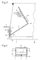
- FIG. 3 shows an enlarged view of a detail from FIG. 2 and
- FIG. 4 shows a view of the rear end of the device.
- 1 consists essentially of three rail-shaped sliding surfaces 1, 2 which are arranged in a sliding surface plane 23.
- the - rail-shaped sliding surfaces are firmly connected with webs 3, 4, whereby a rigid construction is achieved. Free surfaces remain between the three sliding surfaces, through which the binder can be filled or applied and which thus form the application area 5 for the binder in the form of two webs.
- Fig. 2 shows a group of components 6 laid in rows.
- a binder layer 7 is to be applied to these with the device according to the invention, in order then to e.g. to be able to lay another group of components.
- the device has a wall plate 8 on each of the two outer sliding surfaces 1 , 2. Between the two wall plates 8, a steering plate 9 is arranged at the rear end which is bent and points to the front end of the device with the buckling edge.Binding agent 10 is filled between the two wall plates 8 in the application area 5 for the binding agent arrow 11 the binder is applied 1 0 by the steering plate 9 to the desired strength as a binder layer 7 on the devices. 6
- Fig. 3 shows in detail a preferred embodiment of the construction of the rear end of the device according to the invention.
- the rail-shaped sliding surfaces in the form of a U-shaped rails which are open at the bottom (reference number 1) are connected to the angular web 4 by means of tabs 12.
- the lower edge 13 of the web 4 is arranged at a certain distance above the sliding surface 1 and this distance determines the maximum thickness of the binding agent layer 7.
- the height of a steering plate bracket 15 is fixed to the web 4 15 connected to the steering plate 9.
- the area of the joint 16 forms the scraper edge 17 of the steering plate 9.
- the steering plate 9 includes an acute angle in its lower part with the sliding surface 1. This causes the binder to be pressed downwards when moving the device in the direction of arrow 11 and towards the scraper edge 17, as a result of which the binder receives the necessary compression After loosening the wing screw 19, the inclination of the steering plate 9 can be adjusted and thus adapted to the respective type of binder.
- the steering plate 9 is kinked in the front region - (kink 20), so that the upper region of the steering plate 9 is arranged facing backwards upwards. This makes it easier to fill in the binder, as can be seen in FIG. 2
- Fig. 4 shows the device in rear view and is self-evident after the above explanations.
- the two wall plates 8 are connected to one another at the upper edge by a web 21, which on the one hand stiffens the construction and on the other hand forms a handle for handling the device.
- a stop surface 22 is formed by extending the outer U-leg The stop surface serves to guide the device along the upper edge of the row of components 6.
- the number of sliding surfaces 1, 2 is variable and depends on the number of binder webs to be applied. In practice, one to three sheets are used, which corresponds to the arrangement of two to four rail-shaped sliding surfaces. The width of the sheets can be freely selected.
- the minimum thickness of the joint is predetermined by appropriate selection of the height of the rails 1, 2. If a steering plate 9 was described in the description of the invention, this does not mean that it must be a plate, but the expression generally means a steering surface through which a smooth removal of the binder is achieved at the desired height.
- the stop surface 22 can also be e.g. welded-on guide flanges can be formed on one of the two outer rails 1 or 2.
- the scraper edge 17 is preferably straight.
- another form of the scraper edge can be used, e.g. curly or serrated
- the angle of inclination of the steering plate 9 has shown that the larger the binder (mortar), the greater it should be in order to achieve a greater contact pressure. With so-called lightweight construction, only low pressure and therefore a smaller angle of inclination is necessary.
Landscapes
- Engineering & Computer Science (AREA)
- Architecture (AREA)
- Mechanical Engineering (AREA)
- Civil Engineering (AREA)
- Structural Engineering (AREA)
- Conveying And Assembling Of Building Elements In Situ (AREA)
Abstract
Description
- Die Erfindung betrifft eine Vorrichtung zum Auftragen von Bindemittel, wie Mörtel, auf reihenförmig verlegte Bauelemente.
- Üblicherweise wird beim Bau von Mauerwerk aus einzelnen Bauelementen das Bindemittel mit einer Kelle händisch auf die horizontalen Flächen aufgetragen, auf die weitere Bauelemente verlegt werden. Das Bindemittel dient einerseits dazu, die Bauelemente miteinander zu verbinden und andererseits dazu, Unebenheiten auszugleichen und durch entsprechende Wahl der Fugenstärke die Höhe des gesamten Bauwerkes den Notwendigkeiten anzupassen.
- Es hat sich gezeigt, daß ein ebenes Auftragen des Bindemittels in der vorgeschriebenen Stärke schwierig zu bewerkstelligen ist. Dies trifft insbesondere für handwerklich nicht so geschulte und erfahrene Baukräfte zu. Mit der vorliegenden Erfindung werden diese Nachteile beseitigt
- Die erfindungsgemäße Vorichtung ist in erster Linie dadurch gekennzeichnet, daß sie ein oder mehrere Gleitflächen, einen Auftragebereich für das Bindemittel und eine quer zur Verschieberichtung der Vorrichtung angeordnete Abziehkante für das Bindemittel aufweist. Weitere vorteilhafte Merkmale der erfindungsgemäßen Vorrichtung sind den Patentansprüchen der nachfolgenden Beschreibung und den Zeichnungen zu entnehmen.
- Im folgenden wird die Erfindung beispielsweise anhand der Zeichnungen näher erläutert Fig. 1 zeigt eine Ansicht der Vorrichtung von unten und Fig. 2 die Vorrichtung im Schnitt nach der Linie II-II in Fig. 1, in Bestriebsstellung auf reihenförmig verlegten Bauelementen. Fig. 3 zeigt in vergrößerter Darstellung einen Ausschnitt aus Fig. 2 und Fig. 4 eine Ansicht des hinteren Endes der Vorrichtung.
- Die Vorrichtung gemäß Fig. 1 besteht im wesentlichen aus drei schienen förmigen Gleitflächen 1, 2 die in einer Gleitflächenebene 23 angeordnet sind. Die - schienenförmigen Gleitflächen sind mit Stegen 3, 4 fest verbunden, wodurch eine starre Konstruktion erzielt ist. Zwischen den drei Gleitflächen verbleiben freie Flächen, durch die das Bindemittel eingefüllt bzw. aufgetragen werden kann und die somit den Auftragebereich 5 für das Bindemittel in - Form zweier Bahnen bilden.
- Fig. 2 zeigt eine Schar reihenförmig verlegter Bauelemente 6. Auf diesen soll mit der erfindungsgemäßen Vorrichtung eine Bindemittelschicht 7 aufgetragen werden, um dann z.B. eine weitere Schar Bauelemente verlegen zu können.
- Die Vorrichtung weist an den beiden äußeren Gleitflächen 1, 2 je eine Wandplatte 8 auf. Zwischen den beiden Wandplatten 8 ist am hinteren Ende ein Lenkblech 9 angeordnet das abgeknickt ist und mit der Knickkante zum vorderen Ende der Vorrichtung weist Das Bindemittel 10 wird zwischen den beiden Wandplatten 8 in den Auftragsbereich 5 für das Bindemittel eingefüllt Beim Verschieben der Vorrichtung in Richtung des Pfeiles 11 wird das Bindemittel 10 durch das Lenkblech 9 in gewünschter Stärke als Bindemittelschicht 7 auf die Bauelemente 6 aufgetragen.
- Die Fig. 3 zeigt im Detail eine bevorzugte Ausführung der Konstruktion des hinteren Endes der erfindungsgemäßen Vorrichtung. Die schienenförmigen Gleitflächen in Form einer nach unten offenen U-förmigen Schienen - (Bezugszeichen 1) sind mittels Laschen 12 mit dem winkelförmigen Steg 4 verbunden. Die untere Kante 13 des Steges 4 ist in einigem Abstand über der Gleitfläche 1 angeordnet und dieser Abstand bestimmt die maximale Stärke der Bindemittelschicht 7. Mittels einer Flügelschraube 14 ist eine Lenkblechlasche 15 in der Höhe verstellbar am Steg 4 befestigt Über das Gelenk 16 ist die Lasche 15 mit dem Lenkblech 9 verbunden. Der Bereich des Gelenkes 16 bildet die Abstreifkante 17 des Lenkbieches 9. Durch Lösen der Flügelschraube 14 kann die Höhe der Abstreifkante 17 über der Gleitfläche 1 leicht eingestellt werden.
- Das Lenkblech 9 schließt in seinem unteren Teil mit der Gleitfläche 1 einen spitzen Winkel ein. Dies bewirkt, daß das Bindemittel beim Verschieben der Vorrichtung in Richtung des Pfeiles 11 nach unten und zur Abstreifkante 17 gepreßt wird, wodurch das Bindemittel die notwendige Verdichtung erhält An den beiden Wandplatten 8 ist das Lenkblech 9 über die bogenförmigen Schlitze 18 und die Flügelschraube 19 befestigt Nach Lösen der Flügelschraube 19 kann die Neigung des Lenkbleches 9 eingestellt werden und damit der jeweiligen Bindemittelart angepaßt werden.
- Das Lenkblech 9 ist im vorderen Bereich abgeknickt - (Knick 20), so daß der obere Bereich des Lenkbleches 9 nach oben rückwärts weisend angeordnet ist. Dadurch wird das Einfüllen des Bindemittels erleichtert, wie in Fig. 2 ersichtlich ist
- Die Fig. 4 zeigt die Vorrichtung in Ansicht von hinten und ist nach den obenstehenden Erläuterungen von selbst verständlich. Die beiden Wandplatten 8 sind an der oberen Kante durch einen Steg 21 miteinander verbunden, wodurch einerseits die Konstruktion versteift wird und andererseits ein Griff für die Handhabung des Gerätes gebildet ist Bei der Gleitfläche 2 ist durch Verlängem des äußeren U-Schenkeis eine Anschlagfläche 22 gebildet Diese Anschlagfläche dient zur Führung der Vorrichtung entlang der Oberkante der Reihe von Bauelementen 6.
- In den Fig. 1 bis 4 ist die Erfindung nur in einem Ausführungsbeispiel dargestellt Abänderungen konstruktiver Art lassen sich selbst verständlich leicht durchführen, ohne den Erfindungsgedanken zu verlassen. Die Zahl der Gleitflächen 1, 2 ist variabel und hängt von der Zahl der aufzutragenden Bindemittelbahnen ab. In der Praxis werden vor allem ein bis drei Bahnen verwendet, was der Anordnung von zwei bis vier schienenförmigen Gleitflächen entspricht Die Breite der Bahnen ist frei wählbar.
- Durch entsprechende Wahl der Höhe der Schienen 1, 2 ist die Mindeststärke der Fuge vorgegeben. Wenn in der Erfindungsbeschreibung ein Lenkblech 9 beschrieben wurde, so bedeutet dies nicht, daß es sich hiebei um ein Blech handeln muß, sondern der Ausdruck bedeutet allgemein eine Lenkfläche, durch die ein glattes Abziehen des Bindemittels in der gewünschten Höhe erzielt wird.
- Die Anschlagfläche 22 kann auch durch z.B. aufgeschweißte Führungsflansche an einer der beiden äußeren Schienen 1 oder 2 gebildet sein.
- Die Abstreifkante 17 ist in bevorzugter Weise gerade ausgeführt Für besondere Anwendungsfälle kann eine andere Form der Abzeihkante Verwendung finden, z.B. geschweift oder gezahnt
- Beim Neigungswinkel des Lenkbleches 9 hat sich gezeigt, daß dieser umso größer sein soll, je größer das Bindemittel (Mörtel) ist, um einen größeren Anpreßdruck zu erzielen. Bei sogenanntem Leichtbaumörtef ist nur geringer Druck und daher ein geringerer Neigungswinkel notwendig.
Claims (14)
Applications Claiming Priority (2)
| Application Number | Priority Date | Filing Date | Title |
|---|---|---|---|
| AT0078285A AT389557B (de) | 1985-03-15 | 1985-03-15 | Vorrichtung zum auftragen von bindemitteln, wie moertel, auf reihenfoermig verlegte bauelemente |
| AT782/85 | 1985-03-15 |
Publications (3)
| Publication Number | Publication Date |
|---|---|
| EP0195771A2 true EP0195771A2 (de) | 1986-09-24 |
| EP0195771A3 EP0195771A3 (en) | 1987-04-22 |
| EP0195771B1 EP0195771B1 (de) | 1990-06-13 |
Family
ID=3499617
Family Applications (1)
| Application Number | Title | Priority Date | Filing Date |
|---|---|---|---|
| EP86890064A Expired - Lifetime EP0195771B1 (de) | 1985-03-15 | 1986-03-17 | Vorrichtung zum Auftragen von Bindemitteln, wie Mörtel, auf reihenförmig verlegte Bauelemente |
Country Status (3)
| Country | Link |
|---|---|
| EP (1) | EP0195771B1 (de) |
| AT (1) | AT389557B (de) |
| DE (1) | DE3671930D1 (de) |
Cited By (1)
| Publication number | Priority date | Publication date | Assignee | Title |
|---|---|---|---|---|
| FR2643834A1 (fr) * | 1989-03-06 | 1990-09-07 | Authie Paul | Appareil pour realiser rapidement des joints de maconnerie de caracteristiques optimales, utilisable plus generalement pour deposer sur un support et former des mortiers, pates et produits visqueux, granuleux ou pulverulents |
Family Cites Families (10)
| Publication number | Priority date | Publication date | Assignee | Title |
|---|---|---|---|---|
| US1780902A (en) * | 1929-02-09 | 1930-11-11 | Robert T Ainslie | Mortar spreader |
| FR1116282A (fr) * | 1954-12-11 | 1956-05-07 | Procédé de jointoiement entre assises et appareil pour sa mise en oeuvre | |
| US3319283A (en) * | 1964-09-24 | 1967-05-16 | Raymond A Delligatti | Applicator |
| DE1684147A1 (de) * | 1967-06-29 | 1971-03-04 | Alphonse Ammann S A | Lehre zur Horizontalverteilung des Moertels beim Verlegen von Back- und Zementsteinen |
| US3545159A (en) * | 1968-07-23 | 1970-12-08 | Max E Brewer | Mortar spreader |
| GB1251820A (de) * | 1968-09-20 | 1971-11-03 | ||
| US3764222A (en) * | 1971-10-01 | 1973-10-09 | W Orthman | Manually operable mortar spreader for brick layers |
| FR2499135A1 (fr) * | 1981-01-30 | 1982-08-06 | Hugues Hubert | Chariot repartiteur de mortier |
| FR2519054A1 (fr) * | 1981-12-24 | 1983-07-01 | Garnier Paul | " boudineur " ou outil permettant un etalement rapide et regulier du ciment sur une rangee de parpaings lors de la construction d'un mur |
| FR2559189A2 (fr) * | 1984-01-12 | 1985-08-09 | Ortiz Antoine | Dispositif pour la repartition du mortier de joint pour la mise en oeuvre des elements de maconnerie |
-
1985
- 1985-03-15 AT AT0078285A patent/AT389557B/de not_active IP Right Cessation
-
1986
- 1986-03-17 EP EP86890064A patent/EP0195771B1/de not_active Expired - Lifetime
- 1986-03-17 DE DE8686890064T patent/DE3671930D1/de not_active Expired - Lifetime
Cited By (2)
| Publication number | Priority date | Publication date | Assignee | Title |
|---|---|---|---|---|
| FR2643834A1 (fr) * | 1989-03-06 | 1990-09-07 | Authie Paul | Appareil pour realiser rapidement des joints de maconnerie de caracteristiques optimales, utilisable plus generalement pour deposer sur un support et former des mortiers, pates et produits visqueux, granuleux ou pulverulents |
| EP0387120A1 (de) * | 1989-03-06 | 1990-09-12 | Jacques Jouffreau | Schnellausfülleinrichtung für die Fugen eines Ziegelsteinwerkes mit optionalen Charakteristika, im allgemeinen für die Abgabe auf einer Stütze und das Formen des Mörtels, des Teiges und der körnigen zähflüssigen oder pulverförmigen Produkte |
Also Published As
| Publication number | Publication date |
|---|---|
| AT389557B (de) | 1989-12-27 |
| EP0195771A3 (en) | 1987-04-22 |
| DE3671930D1 (de) | 1990-07-19 |
| EP0195771B1 (de) | 1990-06-13 |
| ATA78285A (de) | 1989-05-15 |
Similar Documents
| Publication | Publication Date | Title |
|---|---|---|
| EP0108222A2 (de) | Traggestell | |
| DE3032359C2 (de) | Unterkonstruktion zur Befestigung einer Wandbekleidung | |
| DE2611323C3 (de) | Einstellvorrichtung für eine der Höhe nach einstellbare obere Schiene eines Schiebeflügels | |
| EP0195771B1 (de) | Vorrichtung zum Auftragen von Bindemitteln, wie Mörtel, auf reihenförmig verlegte Bauelemente | |
| DE2543174C2 (de) | Halterung für eine hinterlüftbare Bauwerksverkleidung | |
| AT398017B (de) | Stufenweise einstellbarer pflug | |
| DE2841204A1 (de) | Haltevorrichtung fuer wand-bekleidungsplatten | |
| DE3136451C2 (de) | Mehrteiliger Sprungkasten als Turn- und Gymnastikgerät | |
| EP0317937B1 (de) | Schalungsvorrichtung | |
| DE3123953A1 (de) | "winkelprofil zum abschliessen von wand- und bodenbelaegen" | |
| EP0292667B1 (de) | Bausatz, insbesondere für eine Holzhütte | |
| DE2827148C2 (de) | Bausatz zur Halterung von vertikalen Tragprofilen mit Gleitpunkt und Festpunkt zur Befestigung großflächiger plattenförmig ausgebildeter Gegenstände an Gebäuden | |
| DE3744157C2 (de) | ||
| AT394616B (de) | Rahmenfoermiges bauelement | |
| DE2801966C3 (de) | Doppelschaliges Wand- oder Dachelement für Fertighäuser, -hallen und -garagen | |
| DE3429303A1 (de) | Schalungstafel | |
| DE2931963C2 (de) | Mehrgeschossiges Gebäude aus U-förmigen und ebenen Bauelementen aus Beton | |
| DE3016842C2 (de) | Klemmstab für Rieselplatten | |
| DE2158424C3 (de) | Verstellbare Trennwand aus mindestens einem Wandelement | |
| DE8506734U1 (de) | Vorrichtung zum Befestigen von Dachziegeln, Dachpfannen od. dgl. auf Hausdächern | |
| DE2843457A1 (de) | Fassadenverkleidung | |
| DE1950360U (de) | Verstellbarer befestigungsanker fuer verkleidungsplatten an fassaden von bauwerken. | |
| DE1534957C (de) | Schalungsrost fur Betonwande od dgl | |
| AT1970U1 (de) | Klammer zur befestigung von fassadenplatten an einer metall-unterkonstruktion für hinterlüftete fassaden | |
| DE2428599B2 (de) | Lehre zum aufbringen von verputz |
Legal Events
| Date | Code | Title | Description |
|---|---|---|---|
| PUAI | Public reference made under article 153(3) epc to a published international application that has entered the european phase |
Free format text: ORIGINAL CODE: 0009012 |
|
| AK | Designated contracting states |
Kind code of ref document: A2 Designated state(s): CH DE FR GB LI |
|
| PUAL | Search report despatched |
Free format text: ORIGINAL CODE: 0009013 |
|
| AK | Designated contracting states |
Kind code of ref document: A3 Designated state(s): CH DE FR GB LI |
|
| 17P | Request for examination filed |
Effective date: 19871016 |
|
| 17Q | First examination report despatched |
Effective date: 19880930 |
|
| GRAA | (expected) grant |
Free format text: ORIGINAL CODE: 0009210 |
|
| AK | Designated contracting states |
Kind code of ref document: B1 Designated state(s): CH DE FR GB LI |
|
| GBT | Gb: translation of ep patent filed (gb section 77(6)(a)/1977) | ||
| REF | Corresponds to: |
Ref document number: 3671930 Country of ref document: DE Date of ref document: 19900719 |
|
| ET | Fr: translation filed | ||
| PLBE | No opposition filed within time limit |
Free format text: ORIGINAL CODE: 0009261 |
|
| STAA | Information on the status of an ep patent application or granted ep patent |
Free format text: STATUS: NO OPPOSITION FILED WITHIN TIME LIMIT |
|
| 26N | No opposition filed | ||
| PGFP | Annual fee paid to national office [announced via postgrant information from national office to epo] |
Ref country code: CH Payment date: 19990316 Year of fee payment: 14 |
|
| PGFP | Annual fee paid to national office [announced via postgrant information from national office to epo] |
Ref country code: DE Payment date: 19990317 Year of fee payment: 14 |
|
| PGFP | Annual fee paid to national office [announced via postgrant information from national office to epo] |
Ref country code: GB Payment date: 19990318 Year of fee payment: 14 |
|
| PGFP | Annual fee paid to national office [announced via postgrant information from national office to epo] |
Ref country code: FR Payment date: 19990325 Year of fee payment: 14 |
|
| PG25 | Lapsed in a contracting state [announced via postgrant information from national office to epo] |
Ref country code: GB Free format text: LAPSE BECAUSE OF NON-PAYMENT OF DUE FEES Effective date: 20000317 |
|
| PG25 | Lapsed in a contracting state [announced via postgrant information from national office to epo] |
Ref country code: LI Free format text: LAPSE BECAUSE OF NON-PAYMENT OF DUE FEES Effective date: 20000331 Ref country code: CH Free format text: LAPSE BECAUSE OF NON-PAYMENT OF DUE FEES Effective date: 20000331 |
|
| GBPC | Gb: european patent ceased through non-payment of renewal fee |
Effective date: 20000317 |
|
| REG | Reference to a national code |
Ref country code: CH Ref legal event code: PL |
|
| PG25 | Lapsed in a contracting state [announced via postgrant information from national office to epo] |
Ref country code: FR Free format text: LAPSE BECAUSE OF NON-PAYMENT OF DUE FEES Effective date: 20001130 |
|
| REG | Reference to a national code |
Ref country code: FR Ref legal event code: ST |
|
| PG25 | Lapsed in a contracting state [announced via postgrant information from national office to epo] |
Ref country code: DE Free format text: LAPSE BECAUSE OF NON-PAYMENT OF DUE FEES Effective date: 20010103 |