EP0194467B1 - Einrichtung zum Einbringen einer Hülse in ein Rohr eines Dampferzeugers - Google Patents
Einrichtung zum Einbringen einer Hülse in ein Rohr eines Dampferzeugers Download PDFInfo
- Publication number
- EP0194467B1 EP0194467B1 EP86101950A EP86101950A EP0194467B1 EP 0194467 B1 EP0194467 B1 EP 0194467B1 EP 86101950 A EP86101950 A EP 86101950A EP 86101950 A EP86101950 A EP 86101950A EP 0194467 B1 EP0194467 B1 EP 0194467B1
- Authority
- EP
- European Patent Office
- Prior art keywords
- sleeve
- holding device
- clamping
- tube
- clamping jaws
- Prior art date
- Legal status (The legal status is an assumption and is not a legal conclusion. Google has not performed a legal analysis and makes no representation as to the accuracy of the status listed.)
- Expired
Links
- 230000008878 coupling Effects 0.000 claims description 4
- 238000010168 coupling process Methods 0.000 claims description 4
- 238000005859 coupling reaction Methods 0.000 claims description 4
- 238000000034 method Methods 0.000 claims description 3
- 241000209035 Ilex Species 0.000 description 6
- 238000003780 insertion Methods 0.000 description 6
- 230000037431 insertion Effects 0.000 description 6
- 238000003466 welding Methods 0.000 description 3
- 238000013461 design Methods 0.000 description 2
- 238000012360 testing method Methods 0.000 description 2
- 244000089486 Phragmites australis subsp australis Species 0.000 description 1
- 238000006073 displacement reaction Methods 0.000 description 1
- 238000007689 inspection Methods 0.000 description 1
- 230000002093 peripheral effect Effects 0.000 description 1
- 239000000523 sample Substances 0.000 description 1
- 238000012549 training Methods 0.000 description 1
Images


Classifications
-
- F—MECHANICAL ENGINEERING; LIGHTING; HEATING; WEAPONS; BLASTING
- F22—STEAM GENERATION
- F22B—METHODS OF STEAM GENERATION; STEAM BOILERS
- F22B37/00—Component parts or details of steam boilers
-
- B—PERFORMING OPERATIONS; TRANSPORTING
- B23—MACHINE TOOLS; METAL-WORKING NOT OTHERWISE PROVIDED FOR
- B23P—METAL-WORKING NOT OTHERWISE PROVIDED FOR; COMBINED OPERATIONS; UNIVERSAL MACHINE TOOLS
- B23P19/00—Machines for simply fitting together or separating metal parts or objects, or metal and non-metal parts, whether or not involving some deformation; Tools or devices therefor so far as not provided for in other classes
- B23P19/02—Machines for simply fitting together or separating metal parts or objects, or metal and non-metal parts, whether or not involving some deformation; Tools or devices therefor so far as not provided for in other classes for connecting objects by press fit or for detaching same
- B23P19/022—Extracting or inserting relatively long parts
-
- F—MECHANICAL ENGINEERING; LIGHTING; HEATING; WEAPONS; BLASTING
- F22—STEAM GENERATION
- F22B—METHODS OF STEAM GENERATION; STEAM BOILERS
- F22B37/00—Component parts or details of steam boilers
- F22B37/002—Component parts or details of steam boilers specially adapted for nuclear steam generators, e.g. maintenance, repairing or inspecting equipment not otherwise provided for
- F22B37/003—Maintenance, repairing or inspecting equipment positioned in or via the headers
-
- F—MECHANICAL ENGINEERING; LIGHTING; HEATING; WEAPONS; BLASTING
- F28—HEAT EXCHANGE IN GENERAL
- F28F—DETAILS OF HEAT-EXCHANGE AND HEAT-TRANSFER APPARATUS, OF GENERAL APPLICATION
- F28F11/00—Arrangements for sealing leaky tubes and conduits
- F28F11/02—Arrangements for sealing leaky tubes and conduits using obturating elements, e.g. washers, inserted and operated independently of each other
-
- F—MECHANICAL ENGINEERING; LIGHTING; HEATING; WEAPONS; BLASTING
- F28—HEAT EXCHANGE IN GENERAL
- F28F—DETAILS OF HEAT-EXCHANGE AND HEAT-TRANSFER APPARATUS, OF GENERAL APPLICATION
- F28F11/00—Arrangements for sealing leaky tubes and conduits
- F28F11/06—Arrangements for sealing leaky tubes and conduits using automatic tube obturating appliances
-
- Y—GENERAL TAGGING OF NEW TECHNOLOGICAL DEVELOPMENTS; GENERAL TAGGING OF CROSS-SECTIONAL TECHNOLOGIES SPANNING OVER SEVERAL SECTIONS OF THE IPC; TECHNICAL SUBJECTS COVERED BY FORMER USPC CROSS-REFERENCE ART COLLECTIONS [XRACs] AND DIGESTS
- Y10—TECHNICAL SUBJECTS COVERED BY FORMER USPC
- Y10S—TECHNICAL SUBJECTS COVERED BY FORMER USPC CROSS-REFERENCE ART COLLECTIONS [XRACs] AND DIGESTS
- Y10S122/00—Liquid heaters and vaporizers
- Y10S122/14—Tube replacement
Definitions
- the invention relates to a device for inserting a sleeve into a tube of a steam generator, which ends in a tube sheet delimited by a chamber, which is accessible via an opening, the device comprising a holding plate which can be fixed relative to the tube sheet and a holding plate along this holding plate in the axial direction of the Rohres movable holding device for the sleeve.
- Such a device is known from DE-A-3 122 660.
- a manipulator for inspection or repair of steam generator pipes which can be inserted remotely into a steam generator chamber, is specified there. Tools and test probes are brought to the pipes to be tested in a guide hose. If a holding device for a sleeve to be inserted into a steam generator tube were arranged on the device carrier, the possible length of the sleeves to be inserted would be considerably reduced because of the height of the carrier and because of the sleeve protruding from the carrier in the direction of the tube sheet before the insertion process.
- the movable holding device has clamping jaws and a stationary clamping device is integrated in the holding plate, the clamping pieces of which have the same central axis as the clamping jaws of the movable holding device and which for receiving a sleeve by resilient pressure pieces with spring force acting perpendicular to the central axis It can be actuated that the clamping jaws of the movable holding device 25 have a stepped partial area facing the tube plate and, when the sleeve is not in the clamping area, can be moved together to such an extent that the outer diameter of this partial area is larger than the inner diameter and the same size as the outer diameter of a tube.
- the holding device thus transfers the sleeve to a stationary device, which holds the sleeve in place during a return stroke of the holding device, with an insertion stroke. Due to the introduction in several partial strokes, the holding device, which can be moved in the axial direction of the steam generator tubes, can have a low overall height, so that even in the case of a spherically shaped chamber, corresponding sleeves can still be inserted without difficulty at tube positions located near the periphery. Since the housing of the holding device is penetrated by the sleeve in the axial direction, the remaining overall height of the holding device will have almost no influence on the sleeve length that can be used.
- the holding plate preferably carries a rodless, pressure medium-actuated cylinder, the piston of which is detachably connected to the holding device, which can be moved in the axial direction of the steam generator tubes, via a bracket which projects from the cylinder on the circumferential side.
- a compact, weight-saving device is created by using the holding plate both for receiving the stationary clamping device and for holding the holding device which can be moved in the axial direction of the steam generator tubes.
- the detachable connection between the bracket and the holding device makes it easy to replace the clamping device with another device, e.g. for welding the sleeves.
- the stationary clamping device is arranged in an insert which is detachably fastened to the holding device.
- the space created after removal of this insert allows a tool or a test device to be brought up to a pipe position.
- a tool can be held in the holding device movable in the axial direction of the steam generator tubes or can be attached to the cylinder instead of this holding device.
- the holding plate is equipped with interchangeable centering elements and / or a spreading finger.
- each clamping piece is shell-shaped and has sliding pieces projecting from its outer contour, which protrude into guide slots of the holding plates.
- the clamping jaws be arranged in a housing of the holding device which can be moved in the axial direction of the tubes and that they are positively guided relative to the housing of the holding device during their adjustment movement.
- the device is preferably carried by a manipulator located in the chamber or by a spreading finger which projects from the holding plate and projects into a steam generator tube via a coupling part which engages on the cylinder jacket.
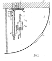
- FIG. 1 shows an overview of the arrangement of a device 1 for introducing a sleeve 2 into a tube 3 of a steam generator 4.
- the steam generator only one tube sheet 5, into which several thousand tubes 3 can end, and one adjacent to the tube sheet 5
- Chamber 6 formed hemispherical. The chamber 6 and thus also each tube 3 ending in the tube plate 5 is accessible through an opening 7.
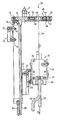
- the device 1 drawn on a larger scale in FIG. 2 is introduced into the chamber 6 via the opening 7 and is fixed relative to the tube sheet 5.
- centering pins 9 are attached to a holding plate, which can be inserted into a tube 3 of the tube sheet 5.
- the centering pins 9 can also be replaced by centering plates 10 shown in FIG. 4, which, with a corresponding design of the tube sheet 5, each encompass a tube 3 projecting from the tube sheet into the chamber 6 on the circumference.
- Figures 3 and 4 show that the respective receiving bore 11 in the holding plate 8 for the centering pin 9 and the centering plate 10 are of identical design.
- the optional use of a centering pin 9 or a centering plate 10 is therefore given.
- a nut 65 is used to fix the centering pin 9 or centering plate 10 relative to the holding plate 8.
- An expansion finger (not shown) for holding the holding plate 8 relative to the tube plate 5 can also be inserted into the receiving bore 11.
- the device 1 is held by a manipulator 12 likewise arranged in the chamber 6.
- a rodless pressure medium-actuated cylinder 14 fastened to the underside of the holding plate 8 by means of screws 13 has two tabs 15.
- a coupling piece 18 is fastened to them via screws 16, 17 and engages in a corresponding counterpart of a manipulator 12 indicated by dash-dotted lines in FIG.
- a bracket 21 projects from a piston (not shown) of the cylinder 14, which can be controlled via two pneumatic connections 19, 20, and carries a prism guide 23 with the interposition of a plate 22. Screw and pin connections secure these components in their position relative to one another.
- a counterpart of the prism guide 23 is assigned to a housing 24 of a holding device 25 and leads to a self-locking locking between the holding device 25 and the bracket 21. The holding device 25 can thus be moved in the axial direction of the tubes 3 via the piston of the cylinder 14.
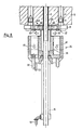
- FIGS. 6 to 9 which, among other things, show a holding device 25 cut along the line IV-IV of FIG. 2, there are two counter-operating in the housing 24 screwed together from side 26, front plates 27 and a base plate 28
- Tensioning cylinders 29, 30 arranged and fastened by means of screws 31 to each side plate 26. They are controlled via pneumatic connections 32, 33.
- Each piston rod 34 of the clamping cylinders 29, 30 carries, via a screw 35, a cup-shaped clamping jaw 36 for holding the sleeve 2.
- a guide piece 37 which is flared downwards is screwed into the base plate 28 the further course of the base plate 28 is provided with a bore 38.
- the bores 38 have such a large diameter with the same central axis 39 that the sleeve 2 can easily be passed through in order to get into the clamping area of the holding device 25.
- the clamping jaws 36 are slidably guided in a tongue and groove connection 40 existing between them and the base plate 28, so that an exact course of movement is ensured.
- FIG. 5 which, viewed in the direction of arrow V in FIG. 2, only shows the completely retracted clamping jaws 36, the portion 41 of the clamping jaws 36 arranged within the housing 24 has a rectangular cross section.
- FIG. 5a shows the clamping jaws 36 with a sleeve clamped in between in the direction of arrow 43 in FIG 2. Around the slot width designated 44 between the clamping jaws 36, they are further together when they assume the position described in FIG. 5. The purpose of this training will be discussed in the further course of the description.
- the holding plate 8 is assigned clamping pieces 45.
- a disc 46 arranged in a recess in the holding plate 8 together with a cover 47 serves as a holder for these clamping pieces.
- the cover 47 is connected with screws 48 both to the holding plate 8 and to the disc 46.
- threaded holes 51 are made in the disc 46 which receive resilient pressure pieces 52. In their relieved position, they press the clamping pieces 45 into the position shown in FIG. 6a, which shows a view of FIG. 2 in the direction of arrow 53.
- the clamping jaws 36 of the holding device 25 have moved into their open position in the direction of arrow 55.
- the sleeve 2 is pushed by hand or with a gripper, not shown, through the conically expanded guide piece 37 into the clamping area of the holding device 25.
- the closing movement of the clamping jaws 36 in the direction of arrow 56 takes place via a control panel (not shown) via the clamping cylinders 29, 30.
- the sleeve 2 is thus in the position shown in FIG. 7 and is held by the holding device 25.
- FIG. 8 now shows that after the completion of a partial stroke, the clamping jaws 36 of the holding device 25 open in the direction of arrow 60 in order to carry out the return stroke in the direction of arrow 61 without the sleeve. Due to the resilient pressure pieces 52 acting in the direction of arrow 62, the tension pieces 45 of the stationary tensioning device 63 are inevitably pressed against the peripheral surface of the sleeve 2 and thus hold the same in their position reached after the partial stroke.
- the clamping jaws 36 again grip the sleeve 2 and push it further into a steam generator tube 3 in a further partial stroke, overcoming the friction between the clamping pieces 45 and sleeve 2.
- the spring force of the pressure pieces 52 is designed such that they enable the sleeve 2 to be pushed through and hold the sleeve 2 in position during the return stroke of the holding device 25.
- the partial strokes are continued in the manner described until, after a return stroke, the end faces 59 of the clamping jaws 36 are able to grip under the lower end of the sleeve 2.
- the clamping jaws 36 are moved together into the position described with reference to FIG. 5.
- the outside diameter of the offset portion 42 of the clamping jaws 36 takes on a dimension that is larger than the inside diameter of a steam generator tube 3.
- the outer diameter of the offset portion 42 is preferably as large as that of a steam generator tube 3.
- the collapsed jaws 36 of the holding device 25 have run through the clamping pieces 45 after the run-up to the bevel 58 of the clamping pieces 45 of the stationary clamping device 63 until the flange 64 of the sleeve 2 comes to rest on the end face of the steam generator tube 3.
- the partial stroke is continued until the end faces 59 of the clamping jaws 36 come into contact with the end face of the steam generator tube 3.
- the clamping pieces 45 pass through the clamping jaws 36, an exact positioning of the lower sleeve end relative to the end face of a steam generator tube 3 ending in the tube sheet 5 is achieved.
- the outer diameter of the lower end of the sleeve 2 is provided with knobs, not shown, which cause easy jamming between the steam generator tube 3 and the sleeve 2. This jamming holds the sleeve in position after the holding device 25 has moved away until it is fastened to the steam generator tube 3 by welding.
- the entire stationary clamping device 63 can be removed by loosening the screws 48 (FIG. 2).
- the resulting space around the steam generator tube 3 equipped with the sleeve 2 allows the sleeve to be welded with the aid of a welding device which can be used instead of the clamping device 25 via the prism guide 23.
Landscapes
- Engineering & Computer Science (AREA)
- Physics & Mathematics (AREA)
- Mechanical Engineering (AREA)
- Thermal Sciences (AREA)
- General Engineering & Computer Science (AREA)
- High Energy & Nuclear Physics (AREA)
- Monitoring And Testing Of Nuclear Reactors (AREA)
- Automatic Assembly (AREA)
- Rigid Pipes And Flexible Pipes (AREA)
Applications Claiming Priority (2)
| Application Number | Priority Date | Filing Date | Title |
|---|---|---|---|
| DE3509177A DE3509177C1 (de) | 1985-03-14 | 1985-03-14 | Einrichtung zum Einbringen eines zylindrischen Koerpers,insbesondere einer Huelse,in ein Rohr eines Dampferzeugers |
| DE3509177 | 1985-03-14 |
Publications (3)
| Publication Number | Publication Date |
|---|---|
| EP0194467A2 EP0194467A2 (de) | 1986-09-17 |
| EP0194467A3 EP0194467A3 (en) | 1986-12-03 |
| EP0194467B1 true EP0194467B1 (de) | 1988-08-24 |
Family
ID=6265213
Family Applications (1)
| Application Number | Title | Priority Date | Filing Date |
|---|---|---|---|
| EP86101950A Expired EP0194467B1 (de) | 1985-03-14 | 1986-02-15 | Einrichtung zum Einbringen einer Hülse in ein Rohr eines Dampferzeugers |
Country Status (5)
| Country | Link |
|---|---|
| US (1) | US4718377A (cg-RX-API-DMAC7.html) |
| EP (1) | EP0194467B1 (cg-RX-API-DMAC7.html) |
| JP (1) | JPS61228182A (cg-RX-API-DMAC7.html) |
| KR (1) | KR900007597B1 (cg-RX-API-DMAC7.html) |
| DE (1) | DE3509177C1 (cg-RX-API-DMAC7.html) |
Families Citing this family (14)
| Publication number | Priority date | Publication date | Assignee | Title |
|---|---|---|---|---|
| US4771526A (en) * | 1985-10-07 | 1988-09-20 | Westinghouse Electric Corp. | Sleeving of steam generators |
| US4829648A (en) * | 1987-01-27 | 1989-05-16 | Westinghouse Electric Corp. | Apparatus and method for simultaneously loading a reinforcing sleeve and mandrel into a tube |
| DE3812351C1 (cg-RX-API-DMAC7.html) * | 1988-04-14 | 1990-01-11 | Abb Reaktor Gmbh, 6800 Mannheim, De | |
| FR2644281B1 (fr) * | 1989-03-09 | 1991-06-07 | Framatome Sa | Dispositif de stabilisation des tubes du faisceau d'un generateur de vapeur comportant des barres antivibratoires |
| US4989818A (en) * | 1989-06-13 | 1991-02-05 | Tennessee Valley Authority | Nozzle dam remote installation system and technique |
| US5322410A (en) * | 1992-01-22 | 1994-06-21 | Stewart & Stevenson Services, Inc. | Tube bundle extractor |
| US7314343B2 (en) * | 2002-07-22 | 2008-01-01 | Westinghouse Electric Co. Llc | Miniature manipulator for servicing the interior of nuclear steam generator tubes |
| US8746089B2 (en) | 2009-01-19 | 2014-06-10 | Babcock & Wilcox Nuclear Energy, Inc. | Apparatus for automated positioning of eddy current test probe |
| JP2012040674A (ja) * | 2010-08-23 | 2012-03-01 | Mitsubishi Heavy Ind Ltd | クランパ、水室内作業装置およびクランプ方法 |
| JP5796780B2 (ja) * | 2012-02-03 | 2015-10-21 | 三菱自動車工業株式会社 | ワーク圧入方法及び装置 |
| DE102016013245B4 (de) | 2016-11-08 | 2025-10-16 | Westinghouse Electric Germany Gmbh | Bohrgerät für das Bearbeiten von Rohren in radioaktiver Umgebung |
| DE102016013247A1 (de) * | 2016-11-08 | 2018-05-09 | Westinghouse Electric Germany Gmbh | Bohrvorrichtung für das Bearbeiten von Rohren an Rohrböden in radioaktiver Umgebung |
| CN111250965B (zh) * | 2020-03-17 | 2021-05-25 | 温岭市鼎工自动化设备科技有限公司 | 一种双扣软管和螺帽的快速上料装置 |
| KR102575698B1 (ko) * | 2021-11-04 | 2023-09-08 | 두산에너빌리티 주식회사 | 증기발생기의 이물질 제거 장치 및 이를 이용한 증기발생기의 이물질 제거 방법 |
Family Cites Families (13)
| Publication number | Priority date | Publication date | Assignee | Title |
|---|---|---|---|---|
| AT326779B (de) * | 1968-07-01 | 1975-12-29 | Waagner Biro Ag | Fernbediente rohrverschliesseinrichtung |
| NL7307086A (cg-RX-API-DMAC7.html) * | 1973-05-21 | 1974-11-25 | ||
| US3912148A (en) * | 1974-04-30 | 1975-10-14 | Babcock & Wilcox Co | Combination welding and brazing device |
| US3935951A (en) * | 1974-07-26 | 1976-02-03 | Ulrich Claus | Apparatus for pulling and replacing heat exchange tubing |
| FR2394374A2 (fr) * | 1977-06-15 | 1979-01-12 | Framatome Sa | Dispositif de positionnement selectif d'un organe sur une plaque tubulaire |
| US4205939A (en) * | 1978-01-30 | 1980-06-03 | Westinghouse Electric Corp. | Apparatus for remotely repairing tubes in a steam generator |
| DE2851475A1 (de) * | 1978-11-28 | 1980-06-04 | Heinz Finzer Kg Maschinenfabri | Vorschubeinrichtung fuer den materialeinzug an metallbearbeitungsmaschinen |
| DE3029811A1 (de) * | 1980-08-06 | 1982-02-18 | Kraftwerk Union AG, 4330 Mülheim | Manipulator zur fernbedienbaren inspektion und gegebenenfalls reparatur von waermtauscherrohren |
| US4406856A (en) * | 1980-09-29 | 1983-09-27 | Westinghouse Electric Corp. | Removal of portions of tubes from steam generator of nuclear reactor |
| DE3122660C2 (de) * | 1981-06-06 | 1986-06-19 | Brown Boveri Reaktor GmbH, 6800 Mannheim | Einrichtung zur Inspektion und/oder zur Reparatur der Rohre eines Dampferzeugers einer Kernkraftanlage |
| DD202972A3 (de) * | 1981-08-07 | 1983-10-05 | Karl Marx Stadt Mech | Automatische zufuehrvorrichtung stangenfoermigen materials, insbesondere fuer holzbearbeitungsmaschinen |
| JPS59214523A (ja) * | 1983-05-20 | 1984-12-04 | Hitachi Ltd | 熱交換器等のu字管の自動插入装置 |
| DE3324777A1 (de) * | 1983-07-08 | 1985-01-17 | Kraftwerk Union AG, 4330 Mülheim | Fernbedienbares werkzeug zum setzen von stopfen in waermetauscherrohre |
-
1985
- 1985-03-14 DE DE3509177A patent/DE3509177C1/de not_active Expired
-
1986
- 1986-02-15 EP EP86101950A patent/EP0194467B1/de not_active Expired
- 1986-02-24 US US06/833,267 patent/US4718377A/en not_active Expired - Fee Related
- 1986-03-11 KR KR1019860001729A patent/KR900007597B1/ko not_active Expired
- 1986-03-13 JP JP61056023A patent/JPS61228182A/ja active Granted
Also Published As
| Publication number | Publication date |
|---|---|
| US4718377A (en) | 1988-01-12 |
| KR860007502A (ko) | 1986-10-13 |
| EP0194467A2 (de) | 1986-09-17 |
| DE3509177C1 (de) | 1986-10-02 |
| JPH038434B2 (cg-RX-API-DMAC7.html) | 1991-02-06 |
| JPS61228182A (ja) | 1986-10-11 |
| KR900007597B1 (ko) | 1990-10-17 |
| EP0194467A3 (en) | 1986-12-03 |
Similar Documents
| Publication | Publication Date | Title |
|---|---|---|
| EP0194467B1 (de) | Einrichtung zum Einbringen einer Hülse in ein Rohr eines Dampferzeugers | |
| DE2552341C3 (de) | Vorrichtung zum Positionieren von Sonden relativ zu einer ebenen Rohrplatte | |
| DE2826106C2 (de) | Anordnung für den Transport einer Positioniervorrichtung im Inneren eines Dampferzeugers | |
| DE19653745B4 (de) | Schnellkupplung | |
| DE3214025A1 (de) | Zweiteilige einrichtung mit kegelhuelse und kegelschaft | |
| DE3851853T2 (de) | Greifvorrichtung. | |
| EP0249079B1 (de) | Vorrichtung zum Zentrieren und Spannen von miteinander zu verschweissenden Rohrwerkstücken | |
| DE3833511C2 (cg-RX-API-DMAC7.html) | ||
| DE3009168C2 (de) | Vorrichtung zum Druckprüfen von Schlauchleitungen mit Metallarmaturen | |
| DE3519970C2 (cg-RX-API-DMAC7.html) | ||
| DE2820165A1 (de) | Werkzeugmaschinen | |
| DE69100110T2 (de) | Verschliesseinrichtung fuer waermetauscher. | |
| EP0630313B1 (de) | Manipulator | |
| EP0173169A1 (de) | Schwenkspanner | |
| DE20306263U1 (de) | Werkstückhalter | |
| DE3812351C1 (cg-RX-API-DMAC7.html) | ||
| DE1299409B (de) | Werkzeug zum Einpressen einer starren Innenhuelse in die Bohrung eines von einer starren Aussenhuelse umschlossenen elastischen Ringkoerpers | |
| DE102019104836A1 (de) | Spannvorrichtung für eine Werkzeugmaschine, insbesondere ein Bearbeitungszentrum | |
| DE4244404C2 (de) | Anwendungseinheit für eine Dichtmasse zum Abdichten von Nietverbindungen | |
| DE9216760U1 (de) | Markiergerät zum Anbringen von Markierungen an Rohrmänteln | |
| DE60204594T2 (de) | Werkzeugwechselvorrichtung | |
| DD263806A5 (de) | Vorrichtung zum zentrieren und spannen von miteinander zu verschweissenden rohrwerkstuecken | |
| DE19809371A1 (de) | Kupplung zur Verbindung von Werkstückgreifern mit einer Handhabungseinrichtung | |
| DE4225281A1 (de) | Meßgerät für Bohrungsdurchmesser | |
| DE3512889C2 (cg-RX-API-DMAC7.html) |
Legal Events
| Date | Code | Title | Description |
|---|---|---|---|
| PUAI | Public reference made under article 153(3) epc to a published international application that has entered the european phase |
Free format text: ORIGINAL CODE: 0009012 |
|
| AK | Designated contracting states |
Kind code of ref document: A2 Designated state(s): BE CH DE FR IT LI NL SE |
|
| PUAL | Search report despatched |
Free format text: ORIGINAL CODE: 0009013 |
|
| AK | Designated contracting states |
Kind code of ref document: A3 Designated state(s): BE CH DE FR IT LI NL SE |
|
| 17P | Request for examination filed |
Effective date: 19870203 |
|
| 17Q | First examination report despatched |
Effective date: 19870522 |
|
| GRAA | (expected) grant |
Free format text: ORIGINAL CODE: 0009210 |
|
| AK | Designated contracting states |
Kind code of ref document: B1 Designated state(s): BE CH FR IT LI NL SE |
|
| ET | Fr: translation filed | ||
| ITF | It: translation for a ep patent filed | ||
| RAP2 | Party data changed (patent owner data changed or rights of a patent transferred) |
Owner name: ABB REAKTOR GMBH |
|
| NLT2 | Nl: modifications (of names), taken from the european patent patent bulletin |
Owner name: ABB REAKTOR GMBH TE MANNHEIM, BONDSREPUBLIEK DUITS |
|
| PLBE | No opposition filed within time limit |
Free format text: ORIGINAL CODE: 0009261 |
|
| STAA | Information on the status of an ep patent application or granted ep patent |
Free format text: STATUS: NO OPPOSITION FILED WITHIN TIME LIMIT |
|
| 26N | No opposition filed | ||
| REG | Reference to a national code |
Ref country code: DE Ref legal event code: 8566 |
|
| BECN | Be: change of holder's name |
Effective date: 19880824 |
|
| ITTA | It: last paid annual fee | ||
| PGFP | Annual fee paid to national office [announced via postgrant information from national office to epo] |
Ref country code: NL Payment date: 19930228 Year of fee payment: 8 |
|
| PG25 | Lapsed in a contracting state [announced via postgrant information from national office to epo] |
Ref country code: NL Effective date: 19940901 |
|
| NLV4 | Nl: lapsed or anulled due to non-payment of the annual fee | ||
| EAL | Se: european patent in force in sweden |
Ref document number: 86101950.3 |
|
| PGFP | Annual fee paid to national office [announced via postgrant information from national office to epo] |
Ref country code: CH Payment date: 19951221 Year of fee payment: 11 |
|
| PG25 | Lapsed in a contracting state [announced via postgrant information from national office to epo] |
Ref country code: LI Effective date: 19970228 Ref country code: CH Effective date: 19970228 |
|
| REG | Reference to a national code |
Ref country code: CH Ref legal event code: PL |
|
| PGFP | Annual fee paid to national office [announced via postgrant information from national office to epo] |
Ref country code: SE Payment date: 19981130 Year of fee payment: 14 Ref country code: FR Payment date: 19981130 Year of fee payment: 14 |
|
| PGFP | Annual fee paid to national office [announced via postgrant information from national office to epo] |
Ref country code: BE Payment date: 19981208 Year of fee payment: 14 |
|
| PG25 | Lapsed in a contracting state [announced via postgrant information from national office to epo] |
Ref country code: SE Free format text: LAPSE BECAUSE OF NON-PAYMENT OF DUE FEES Effective date: 20000216 |
|
| PG25 | Lapsed in a contracting state [announced via postgrant information from national office to epo] |
Ref country code: BE Free format text: LAPSE BECAUSE OF NON-PAYMENT OF DUE FEES Effective date: 20000228 |
|
| BERE | Be: lapsed |
Owner name: ABB REAKTOR G.M.B.H. Effective date: 20000228 |
|
| EUG | Se: european patent has lapsed |
Ref document number: 86101950.3 |
|
| PG25 | Lapsed in a contracting state [announced via postgrant information from national office to epo] |
Ref country code: FR Free format text: LAPSE BECAUSE OF NON-PAYMENT OF DUE FEES Effective date: 20001031 |
|
| REG | Reference to a national code |
Ref country code: FR Ref legal event code: ST |
|
| PG25 | Lapsed in a contracting state [announced via postgrant information from national office to epo] |
Ref country code: IT Free format text: LAPSE BECAUSE OF NON-PAYMENT OF DUE FEES;WARNING: LAPSES OF ITALIAN PATENTS WITH EFFECTIVE DATE BEFORE 2007 MAY HAVE OCCURRED AT ANY TIME BEFORE 2007. THE CORRECT EFFECTIVE DATE MAY BE DIFFERENT FROM THE ONE RECORDED. Effective date: 20050215 |