EP0193571B1 - Charpente metallique a trois dimensions composee d'elements independants pour la construction de batiments - Google Patents
Charpente metallique a trois dimensions composee d'elements independants pour la construction de batiments Download PDFInfo
- Publication number
- EP0193571B1 EP0193571B1 EP85904441A EP85904441A EP0193571B1 EP 0193571 B1 EP0193571 B1 EP 0193571B1 EP 85904441 A EP85904441 A EP 85904441A EP 85904441 A EP85904441 A EP 85904441A EP 0193571 B1 EP0193571 B1 EP 0193571B1
- Authority
- EP
- European Patent Office
- Prior art keywords
- accordance
- elements
- spatial framework
- supports
- insulating
- Prior art date
- Legal status (The legal status is an assumption and is not a legal conclusion. Google has not performed a legal analysis and makes no representation as to the accuracy of the status listed.)
- Expired
Links
- 239000002184 metal Substances 0.000 title claims abstract description 20
- 230000003068 static effect Effects 0.000 claims abstract description 12
- 125000006850 spacer group Chemical group 0.000 claims description 25
- 239000011120 plywood Substances 0.000 claims description 2
- 239000004020 conductor Substances 0.000 claims 2
- 238000010276 construction Methods 0.000 abstract description 7
- 238000009413 insulation Methods 0.000 abstract description 6
- 230000015572 biosynthetic process Effects 0.000 abstract description 2
- 239000000463 material Substances 0.000 description 7
- 238000013461 design Methods 0.000 description 5
- 239000011810 insulating material Substances 0.000 description 3
- 238000012986 modification Methods 0.000 description 3
- 230000004048 modification Effects 0.000 description 3
- 238000000926 separation method Methods 0.000 description 3
- 229920001875 Ebonite Polymers 0.000 description 2
- 230000008901 benefit Effects 0.000 description 2
- 238000004519 manufacturing process Methods 0.000 description 2
- 238000012795 verification Methods 0.000 description 2
- 239000002023 wood Substances 0.000 description 2
- 230000006978 adaptation Effects 0.000 description 1
- 230000004888 barrier function Effects 0.000 description 1
- 239000002131 composite material Substances 0.000 description 1
- 230000006835 compression Effects 0.000 description 1
- 238000007906 compression Methods 0.000 description 1
- 238000009833 condensation Methods 0.000 description 1
- 230000005494 condensation Effects 0.000 description 1
- 230000001419 dependent effect Effects 0.000 description 1
- 238000011161 development Methods 0.000 description 1
- 230000018109 developmental process Effects 0.000 description 1
- 238000005265 energy consumption Methods 0.000 description 1
- 239000000945 filler Substances 0.000 description 1
- 238000009434 installation Methods 0.000 description 1
- 239000012774 insulation material Substances 0.000 description 1
- 230000010354 integration Effects 0.000 description 1
- 238000005304 joining Methods 0.000 description 1
- 239000004033 plastic Substances 0.000 description 1
- 238000009417 prefabrication Methods 0.000 description 1
- 238000004080 punching Methods 0.000 description 1
- 238000003860 storage Methods 0.000 description 1
- 238000012546 transfer Methods 0.000 description 1
- 238000003466 welding Methods 0.000 description 1
Images


Classifications
-
- E—FIXED CONSTRUCTIONS
- E04—BUILDING
- E04B—GENERAL BUILDING CONSTRUCTIONS; WALLS, e.g. PARTITIONS; ROOFS; FLOORS; CEILINGS; INSULATION OR OTHER PROTECTION OF BUILDINGS
- E04B1/00—Constructions in general; Structures which are not restricted either to walls, e.g. partitions, or floors or ceilings or roofs
- E04B1/18—Structures comprising elongated load-supporting parts, e.g. columns, girders, skeletons
- E04B1/30—Structures comprising elongated load-supporting parts, e.g. columns, girders, skeletons the supporting parts being composed of two or more materials; Composite steel and concrete constructions
-
- E—FIXED CONSTRUCTIONS
- E04—BUILDING
- E04B—GENERAL BUILDING CONSTRUCTIONS; WALLS, e.g. PARTITIONS; ROOFS; FLOORS; CEILINGS; INSULATION OR OTHER PROTECTION OF BUILDINGS
- E04B1/00—Constructions in general; Structures which are not restricted either to walls, e.g. partitions, or floors or ceilings or roofs
- E04B1/18—Structures comprising elongated load-supporting parts, e.g. columns, girders, skeletons
- E04B1/24—Structures comprising elongated load-supporting parts, e.g. columns, girders, skeletons the supporting parts consisting of metal
-
- E—FIXED CONSTRUCTIONS
- E04—BUILDING
- E04B—GENERAL BUILDING CONSTRUCTIONS; WALLS, e.g. PARTITIONS; ROOFS; FLOORS; CEILINGS; INSULATION OR OTHER PROTECTION OF BUILDINGS
- E04B2/00—Walls, e.g. partitions, for buildings; Wall construction with regard to insulation; Connections specially adapted to walls
- E04B2/74—Removable non-load-bearing partitions; Partitions with a free upper edge
- E04B2/7407—Removable non-load-bearing partitions; Partitions with a free upper edge assembled using frames with infill panels or coverings only; made-up of panels and a support structure incorporating posts
- E04B2/7409—Removable non-load-bearing partitions; Partitions with a free upper edge assembled using frames with infill panels or coverings only; made-up of panels and a support structure incorporating posts special measures for sound or thermal insulation, including fire protection
- E04B2/7412—Posts or frame members specially adapted for reduced sound or heat transmission
-
- E—FIXED CONSTRUCTIONS
- E04—BUILDING
- E04B—GENERAL BUILDING CONSTRUCTIONS; WALLS, e.g. PARTITIONS; ROOFS; FLOORS; CEILINGS; INSULATION OR OTHER PROTECTION OF BUILDINGS
- E04B1/00—Constructions in general; Structures which are not restricted either to walls, e.g. partitions, or floors or ceilings or roofs
- E04B2001/0053—Buildings characterised by their shape or layout grid
- E04B2001/0076—Buildings with specific right-angled horizontal layout grid
-
- E—FIXED CONSTRUCTIONS
- E04—BUILDING
- E04B—GENERAL BUILDING CONSTRUCTIONS; WALLS, e.g. PARTITIONS; ROOFS; FLOORS; CEILINGS; INSULATION OR OTHER PROTECTION OF BUILDINGS
- E04B1/00—Constructions in general; Structures which are not restricted either to walls, e.g. partitions, or floors or ceilings or roofs
- E04B1/18—Structures comprising elongated load-supporting parts, e.g. columns, girders, skeletons
- E04B1/24—Structures comprising elongated load-supporting parts, e.g. columns, girders, skeletons the supporting parts consisting of metal
- E04B1/2403—Connection details of the elongated load-supporting parts
- E04B2001/2448—Connections between open section profiles
-
- E—FIXED CONSTRUCTIONS
- E04—BUILDING
- E04B—GENERAL BUILDING CONSTRUCTIONS; WALLS, e.g. PARTITIONS; ROOFS; FLOORS; CEILINGS; INSULATION OR OTHER PROTECTION OF BUILDINGS
- E04B1/00—Constructions in general; Structures which are not restricted either to walls, e.g. partitions, or floors or ceilings or roofs
- E04B1/18—Structures comprising elongated load-supporting parts, e.g. columns, girders, skeletons
- E04B1/24—Structures comprising elongated load-supporting parts, e.g. columns, girders, skeletons the supporting parts consisting of metal
- E04B2001/2466—Details of the elongated load-supporting parts
- E04B2001/2469—Profile with an array of connection holes
-
- E—FIXED CONSTRUCTIONS
- E04—BUILDING
- E04B—GENERAL BUILDING CONSTRUCTIONS; WALLS, e.g. PARTITIONS; ROOFS; FLOORS; CEILINGS; INSULATION OR OTHER PROTECTION OF BUILDINGS
- E04B1/00—Constructions in general; Structures which are not restricted either to walls, e.g. partitions, or floors or ceilings or roofs
- E04B1/18—Structures comprising elongated load-supporting parts, e.g. columns, girders, skeletons
- E04B1/24—Structures comprising elongated load-supporting parts, e.g. columns, girders, skeletons the supporting parts consisting of metal
- E04B2001/2466—Details of the elongated load-supporting parts
- E04B2001/2472—Elongated load-supporting part formed from a number of parallel profiles
-
- E—FIXED CONSTRUCTIONS
- E04—BUILDING
- E04B—GENERAL BUILDING CONSTRUCTIONS; WALLS, e.g. PARTITIONS; ROOFS; FLOORS; CEILINGS; INSULATION OR OTHER PROTECTION OF BUILDINGS
- E04B1/00—Constructions in general; Structures which are not restricted either to walls, e.g. partitions, or floors or ceilings or roofs
- E04B1/18—Structures comprising elongated load-supporting parts, e.g. columns, girders, skeletons
- E04B1/24—Structures comprising elongated load-supporting parts, e.g. columns, girders, skeletons the supporting parts consisting of metal
- E04B2001/2481—Details of wall panels
-
- E—FIXED CONSTRUCTIONS
- E04—BUILDING
- E04B—GENERAL BUILDING CONSTRUCTIONS; WALLS, e.g. PARTITIONS; ROOFS; FLOORS; CEILINGS; INSULATION OR OTHER PROTECTION OF BUILDINGS
- E04B1/00—Constructions in general; Structures which are not restricted either to walls, e.g. partitions, or floors or ceilings or roofs
- E04B1/18—Structures comprising elongated load-supporting parts, e.g. columns, girders, skeletons
- E04B1/24—Structures comprising elongated load-supporting parts, e.g. columns, girders, skeletons the supporting parts consisting of metal
- E04B2001/2496—Shear bracing therefor
Definitions
- the present invention relates to a metal space framework consisting of individual elements for the construction of buildings. It is known to build trusses made of metal profiles. Such a proposal is known for example from German Offenlegungsschrift DE-OS 31 30 427. Another proposal emerges from US Pat. No. 4,205,497.
- FR-A-21 84 676 describes a construction skeleton for buildings of various types, which consists of square, metallic, profiled columns on which crossbeams can be attached using gusset plates. However, this results in a direct metallic connection without an insulating intermediate layer, which forms a thermal bridge between the inner and outer skin of the building. Filling pieces, preferably made of hard rubber, can be hammered into the profiling strips, which then serve to support and fasten wall parts, door frames, windows and the like. These embossed fillers do not have a supporting function.
- the metal skeleton assembly houses which have been further developed from wooden building skeletons, mainly in the United States, for cost reasons, in which essentially the wooden truss is replaced by metal profiles the lack that these prefabricated houses can not be used in all climates.
- the metal profiles form thermal bridges between the inner and outer skin, which is disadvantageous both if the houses have to be air-conditioned on the inside due to high outside temperatures or heated inside because of low outside temperatures.
- the previously known prefabricated houses with a metal skeleton can only be used in balanced temperate zones. In all other zones, the operation of these prefabricated houses is associated with high energy consumption. Due to the thermal load fluctuations, building damage occurs too quickly after a certain period of use. Cracks form and moisture penetrates into the building.
- the invention further relates to an insulating spacer for use in the space framework according to the invention.
- a versatile metal skeleton is created according to the invention, in which all problems of heat transfer between inside and outside are overcome. This applies to thermal insulation or insulation as well as the avoidance of tension and condensation.
- the skeleton uses few, namely essentially three types of elements and profiles, thereby allowing rational division of the prefabrication in a stationary operation, easy transport to the place of use and less expensive assembly.
- the skeleton consists of sheet metal profiles that can be manufactured inexpensively and can be prefabricated in a uniform manner. Since there is no need to specify a grid, these can be arranged in order to adapt to the static requirements in this way without having to keep profiles of different structural strengths in stock.
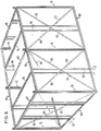
- a spatial framework skeleton is built up from prefabricated metal profile and flat material elements.
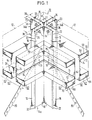
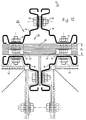
- a load-bearing element is a vertical support, which is differentiated according to the installation location of this support in the spatial framework according to outer wall supports 10 or 40 and pure inner wall supports 50. However, all advantageously consist of four identical individual profiles 14 and 15.
- a house corner with an outer wall support 10 can be seen from four identical individual profiles 14 in the form of an angle, which in this case are composed of an inner profile 14a.
- the angle profiles have flat legs 16 and 18 on the inside and outside, which have bevels 20 and 22, respectively.
- the legs 16 are located in the area of the outer wall and the uniform legs 18 are located in the inner wall area.
- Edge brackets 20 and 22 serve to stiffen the profiles 14a and 14b, the outer bends 20 also serving to fasten an outer skin 12.
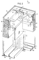
- a support 10 modified with respect to the embodiment according to FIG. 1 with the angle profile 15 is shown in more detail in FIGS. 2 and 2a. The modification is that each leg of the angle 15 has a groove 19 drawn into the interior of the support 10.
- this channel 19 there is a spacer 26 or 27, which is described in more detail below, in such a way that a fastening means remains concealed within the channel 19 and a smooth leg contact surface for the horizontal support 60 with its webs 64 can be connected in this area.
- the principle is the same when using both angle profiles 14 or 15.
- the representation of the principle is simpler on the basis of the profile shape 14 and in practice the profile of the angle 15 is preferred because of the better design of the knots.
- the support 10 is composed of the four identical individual profiles 14a and 14b or 15a and 15b in such a way that a clear distance 36 remains between opposite legs 16 and 18, respectively.
- This distance 36 is particularly important between the legs 16 of an outside profile 14b or 15b and the legs 18 of an inside profile 14a or 15a. At this point, any metallic connection between the legs 16 and 18 over the distance 36 is avoided. This eliminates any metallic heat or cold bridge between the elements on the outside and the elements on the inside of a building constructed according to the invention.
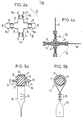
- FIGS. 5a and 5b An exemplary embodiment of how a mechanical connection is made available, which on the one hand avoids any heat flow in the connecting material and yet on the other hand ensures a good mechanical connection and strength, is shown therein.
- the illustrated embodiment shows in the inner part of the two representations a releasable mechanical connection 26 which can be used wherever elements on the outside with elements on the inside of the building are to be kept at the desired distance 36.
- This connection 26 consists of a non-metallic insulating body 28 without thermal conductivity and of sufficient strength. It can be hard rubber or a plastic body. In addition, a certain elasticity of the material is desired for sound insulation.
- Mechanical connecting elements for example threaded screw pins 30, are embedded in the body 28 so as to be resistant to torsion, tension and compression, axially aligned with one another. The torsional, tensile and compressive strength is achieved in that the screw pins 30 end inside the insulating and spacer body 28 in an anchor 32, which can be a simple radial widening, but also a star-shaped plate or the like.
- the two armatures 32 are in turn kept at a sufficient distance within the insulating and spacing body 28, in particular if these armatures 32 are made of metal in order to avoid any heat flow.
- the screw pins 30 are intended to protrude through corresponding openings in the legs 16 and 18 and the finished connection is made by nuts 34 during assembly.
- other detachable or non-detachable connections can also be provided instead of the screw connection.
- screw pins it is possible to provide hollow rivets or similar connecting elements.
- the insulating spacers 28 designed according to FIGS. 5a and 5b are arranged in all corners of the building and outer wall support elements to avoid heat flow between the outer parts, such as the legs 18, which run parallel to the outer skin 12, for example one above the other in a corner support 10 at the required intervals.
- simple, continuous metal spacers 27 can be used between the legs 16, which run transversely to the outer skin 12, in order to save costs. A heat flow need not be prevented in this area since both legs 16 are located in the same outer area of the spatial framework anyway.
- the connections of a diagonal band 80 shown in FIGS. 5a and 5b are used only at those connection points at which such a diagonal band 80 is actually to be connected, which of course applies to only a few such connection points. Therefore, this further embodiment is described in more detail below in connection with the diagonal bands. For most connection points, only the inner part of the spacer 28 according to FIGS. 5a and 5b without a wrapping diagonal band 80 is decisive.
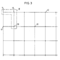
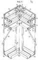
- FIG. 3 there can be three different supports seen in cross section.
- the support 10 already described in detail above is located in an outer corner of the building.
- Adjacent supports 40 are located in the flat area between the outer and inner skin and there are different supports 50 in the interior of the building.
- FIG. 4 the section marked in FIG. 3 with the three different types of supports is shown in more detail.
- the support 10 is located in a corner of the building.
- a further support 40 is located at a distance in the direction of the outer skin 12, it being noted that the representations according to FIGS. 3 and 4 are not true-to-scale representations of an actual building, but a schematic representation of the principle.
- the support 40 is also made up of four identical profile elements 14 as the support 10. However, while the support 10 in the corner of the building has a distance 36 in two intersecting planes or outer walls and is therefore set to a distance 36 in each connecting plane of the elements 14 , the distance 36 need only be maintained in the support 40 parallel to the outer skin 12 by inserting the insulating spacer elements 26 in the manner described above.
- the legs of the profiles 14 can be placed directly on top of one another and connected to one another by simple connecting elements 24 such as screws or rivets.
- a support 50 which is located entirely inside the building, is in any case constructed with legs which are connected directly to one another by connectors 24, as can be seen from the part below in the illustration in FIG. 4. Both supports 40 and 50 are statically connected with a diagonal band 80 in addition to the horizontal main beams not shown in this illustration.
- an inner support 50 is shown with the profile angles 15, which are connected directly and without spacing to rivets 24 in the channels 19. Like all other elements, the support 50 can be filled on the inside with insulating material 43.
- This infill of a prefabricated house skeleton is common and is only mentioned here for the sake of completeness. It is also known to close off the wall structure on the inside with a clamping plate 48.
- Figure 6 is used to provide a schematic perspective overview of a composite spatial framework and to explain those levels that are also installed.
- leg purlins 100 At the bottom are all vertical supports (10, 40) in the wall area in leg purlins 100, which according to FIG. 7 are designed according to the distance 36 so that all feet 42 of the leg 10, 40 are adjusted and with the legs of the preferably U-profile leg purlins 100 in can be connected in a suitable manner.
- there are diagonal tension bands 80 between adjacent supports 10 and 40 which align the spatial truss when tensioning turnbuckles 82 and make it angularly rigid in all two wall levels.
- the space defined by the distance 36 and extending through each outer wall therefore not only enables an advantageous strict separation of the outer wall and inner wall structure, but also a suitable space for a diagonal bracing.
- Perforated flat strip material can preferably be used for the diagonal bracing.
- FIGS. 6, 8, 9 and 10 there are vertically inserted dividing profiles 90 between the supports 10, 40 or 50 composed of four individual elements, which on the one hand serve to provide sufficient support for optionally insertable, soft lining material 94 and on the other hand one To provide additional static support for deriving forces that are introduced from the ceiling via cross members into the truss wall, as will be explained in more detail below.
- additional fastening surfaces are provided for the inner or outer skin.
- division profiles 90 are set in pairs in the area of an outer wall in the purlins 100, but according to the invention such that a distance 92 (FIGS. 6, 8, 9 and 10) is maintained in the direction of the longitudinal axis of each outer wall 12. With this spacing 92 in the area of the outer wall infill, thermal bridges are avoided due to the metal cross-sections of the dividing profiles 10 which are too closely adjacent and which penetrate the insulating material 94 or the air layer of the outer wall infill located in this area transversely thereto.
- a connection for a circumferential horizontal main beam 60 is provided with or without an additional connecting angle 76, which is in an embodiment 1 consists of angled profiles 62 arranged in pairs.
- Each profile 62 has a vertical web 64, on which a box profile 66 is folded at the top and bottom.
- the web 64 is bent at right angles to a flange 68, which is folded back parallel to the plane of the web 64 to an outer web 70.
- the box section 66 is finally completed by a transverse flange 72 with an edge 74.
- Such a profile 62 can be folded in one operation and offers sufficient static strength, whereby the connection between the edge 74 and the web can remain open.
- mechanical improvements in the section modulus of the carrier 60 can also be achieved by punching points or by attaching welding points. This can be achieved in a simple manner in the manufacture of profiles on the same machine, so that an increase in strength does not result in any particular manufacturing difficulties.
- secondary beams 84 can be inserted into the main beams 60, which are of uniform construction and have a smaller cross section.
- the main and secondary beams can, however, also be designed in accordance with a modification from FIGS. 2 and 8 in such a way that the U-legs end with outer webs 70 at low loads and have only one retracted edge 71.
- the retracted edge 71 is brought in a direction that is suitable for holding inserted insulation material.
- the webs 64 are connected when the horizontal main girders 60 with the supports 10, 40 or 50 at floor level are connected to the outer legs 16 and inner legs 18 of the supports 10 or 40, a distance being established between adjacent webs 64 of the same carrier 60, which is greater than the distance 36 is specified. This also ensures a separation of the outer and inner walls in the area of the horizontal beams and any thermal bridge is avoided.
- the insulating spacers 26 are used for this purpose, as shown by way of example in FIG. 1 on the left. In contrast to the illustration in FIG. 5b, these spacers 26 usually have an angular and not a round outline.
- a round outer configuration of the insulating body 28 in accordance with FIG. The insulating body 28 is then surrounded by a sleeve 31 which is normally not present and around which the end of the diagonal band 80 which is deformed into a loop 33 bears.
- the loop 33 is closed with fastening means 35.
- connection points for the diagonal band 80 are produced at the junctions with the spacers 26, for which spacers 27 made of metal can also be used, to the extent that this diagonal band 80 is required.
- the requirement follows from the static load and the necessary bracing. It will normally not be necessary to provide 10, 40 or 50 crossing diagonal bands in each field between supporting columns.
- the box-shaped profile 66 according to FIGS. 7 and 8 can each be provided with a dovetail-shaped or other-shaped longitudinal groove 67.
- the web 64 of the inner profile 62 can be connected to the inner leg 18 of the support 10 or 40 and the outer web 64 of an outer profile can be connected to the outer leg 16 of the support 10 or 40, so that the distance 36 is also preserved between the outer main beam 60.
- secondary girders 84 are inserted to form a load-bearing floor ceiling according to FIG. 8, which have the same structural shape as the main girder 60 and are laid on a suitable grid scale and are connected to the main girders 60.
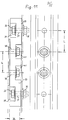
- 11 and 12 show a further modified embodiment of the outer wall region part from the insulating body 28 separating the inner wall region parts without thermal conductivity and with sufficient strength. All lines previously described are identified by the same reference numbers.
- This modified spacer 28 can be used according to FIG. 11 in elevation or according to FIG. 12 in the plan in the support area of the outer skin. 11 can also be seen as an example of a connection in the horizontal beam area.
- the spacer 28 consists of a plywood board 29 and is inserted between the respective metal parts between the outer wall area 12 and the inner wall area at a distance 36.
- the metal parts expediently have a row of holes with a fixed, predetermined distance “L” of, for example, 60 mm. Accordingly, the board 29 also has a perforation at a distance “L”.
- a screw bolt 33 is inserted through a first bore 31, which is provided on the outside with a nut 35, while the screw head of the bolt 33 is located in a recess 37.
- Another bolt 39 is offset by the dimension “L” from the outside with its bolt head in a recess 41 such that it can be provided with a nut 43 (FIG. 12). This series can be continued alternately. In any case, a thermal bridge is easily avoided.
Abstract
Claims (22)
Priority Applications (1)
| Application Number | Priority Date | Filing Date | Title |
|---|---|---|---|
| AT85904441T ATE44063T1 (de) | 1984-08-20 | 1985-08-20 | Metall-raumfachwerk aus einzelelementen zum errichten von gebaeuden. |
Applications Claiming Priority (2)
| Application Number | Priority Date | Filing Date | Title |
|---|---|---|---|
| DE19843430612 DE3430612A1 (de) | 1984-08-20 | 1984-08-20 | Metall-raumfachwerk aus einzelelementen zum errichten von gebaeuden |
| DE3430612 | 1984-08-20 |
Publications (2)
| Publication Number | Publication Date |
|---|---|
| EP0193571A1 EP0193571A1 (fr) | 1986-09-10 |
| EP0193571B1 true EP0193571B1 (fr) | 1989-06-14 |
Family
ID=6243479
Family Applications (1)
| Application Number | Title | Priority Date | Filing Date |
|---|---|---|---|
| EP85904441A Expired EP0193571B1 (fr) | 1984-08-20 | 1985-08-20 | Charpente metallique a trois dimensions composee d'elements independants pour la construction de batiments |
Country Status (4)
| Country | Link |
|---|---|
| US (1) | US4742665A (fr) |
| EP (1) | EP0193571B1 (fr) |
| DE (2) | DE3430612A1 (fr) |
| WO (1) | WO1986001242A1 (fr) |
Families Citing this family (57)
| Publication number | Priority date | Publication date | Assignee | Title |
|---|---|---|---|---|
| FR2613403A1 (fr) * | 1987-04-03 | 1988-10-07 | Bretzner Michel | Pilier, notamment pour constructions a ossature bois et constructions faisant usage de tels piliers |
| US5513473A (en) * | 1992-01-06 | 1996-05-07 | Sucre F.; Alfredo | Prefabricated building system |
| GB9218957D0 (en) * | 1992-09-08 | 1992-10-21 | Perks Arthur T | Graviationally locked structural joint |
| CA2133719A1 (fr) * | 1993-10-05 | 1995-04-06 | Alfredo Sucre-F | Systeme de construction pour batiments prefabriques |
| WO1997032093A1 (fr) * | 1996-03-01 | 1997-09-04 | Bhp Steel (Jla) Pty. Ltd. | Systeme d'isolation |
| US5740648A (en) * | 1996-05-14 | 1998-04-21 | Piccone; Francesco | Modular formwork for concrete |
| US5809726A (en) * | 1996-08-21 | 1998-09-22 | Spude; Gerald T. | Foundation construction system |
| DE19636802A1 (de) * | 1996-09-11 | 1998-03-12 | Ernst Koller | Gebäudeskelett |
| CA2271601C (fr) | 1997-10-17 | 2003-06-17 | The Global Engineering Trust | Elements de coffrage modulaires et methode d'assemblage |
| WO1999049146A1 (fr) * | 1998-03-23 | 1999-09-30 | Cote Claude | Structure murale |
| US6694692B2 (en) * | 1998-10-16 | 2004-02-24 | Francesco Piccone | Modular formwork elements and assembly |
| CA2315401A1 (fr) | 1999-08-13 | 2001-02-13 | Alfredo J. Sucre F. | Poteaux corniers pour systemes de construction prefabriquee |
| US6421972B1 (en) | 2000-04-27 | 2002-07-23 | I Mozaic Trust | Modular wall component with insulative thermal break |
| US6698710B1 (en) | 2000-12-20 | 2004-03-02 | Portland Cement Association | System for the construction of insulated concrete structures using vertical planks and tie rails |
| US6837016B2 (en) | 2001-08-30 | 2005-01-04 | Simmons Robert J | Moment-resistant building frame structure componentry and method |
| US6802169B2 (en) * | 2002-03-18 | 2004-10-12 | Robert J. Simmons | Building frame structure |
| US20050055969A1 (en) * | 2002-03-18 | 2005-03-17 | Simmons Robert J. | Building frame structure |
| US20040200178A1 (en) * | 2003-04-08 | 2004-10-14 | Simmons Robert J. | Matrix frame/panel skin building structure |
| GR1006183B (el) * | 2005-10-07 | 2008-12-08 | Δημητριος Γεωργιου Φαης | Μεθοδος κατασκευης φεροντα οργανισμου (σκελετου) προς ανεγερση κτιριων, με συνδεση μεταξυ τους γραμμικων φορεων ορθογωνικης διατομης και πρισματικης μορφης. |
| FR2906277B1 (fr) * | 2006-09-22 | 2008-12-12 | Apr Entpr Sarl | Procede de construction d'un batiment d'habitation a ossature porteuse metallique et batiment obtenu |
| WO2008119178A1 (fr) * | 2007-04-02 | 2008-10-09 | Cfs Concrete Forming Systems Inc. | Procédés et appareil permettant de créer des revêtements destinés à des structures en béton |
| AU2008324734B2 (en) | 2007-11-09 | 2015-05-07 | Cfs Concrete Forming Systems Inc. | Pivotally activated connector components for form-work systems and methods for use of same |
| WO2009092158A1 (fr) * | 2008-01-21 | 2009-07-30 | Octaform Systems Inc. | Systèmes de coffrage fixe pour fenêtres et autres ouvertures de bâtiment |
| DE102008028672A1 (de) * | 2008-06-17 | 2009-12-24 | Hoesch Schwerter Profile Gmbh | Konstruktionselement für Bauten, einschließlich transportabler Bauten |
| CA2748168C (fr) | 2009-01-07 | 2015-12-15 | Cfs Concrete Forming Systems Inc. | Procedes et appareil pour restaurer, reparer, renforcer et/ou proteger des structures utilisant du beton |
| US8943774B2 (en) | 2009-04-27 | 2015-02-03 | Cfs Concrete Forming Systems Inc. | Methods and apparatus for restoring, repairing, reinforcing and/or protecting structures using concrete |
| US8793953B2 (en) | 2009-02-18 | 2014-08-05 | Cfs Concrete Forming Systems Inc. | Clip-on connection system for stay-in-place form-work |
| EP2591186B1 (fr) | 2010-07-06 | 2019-05-01 | CFS Concrete Forming Systems Inc. | Système de poussée pour réparer des structures |
| AU2012343274B2 (en) | 2011-11-24 | 2017-06-15 | Cfs Concrete Forming Systems Inc. | Stay-in-place formwork with anti-deformation panels |
| US9206614B2 (en) | 2011-11-24 | 2015-12-08 | Cfs Concrete Forming Systems Inc. | Stay-in-place formwork with engaging and abutting connections |
| CA2763058C (fr) | 2012-01-05 | 2014-10-14 | Cascadia Windows Ltd. | Entretoise thermiquement isolante et methodes y faisant appel |
| US10151119B2 (en) | 2012-01-05 | 2018-12-11 | Cfs Concrete Forming Systems Inc. | Tool for making panel-to-panel connections for stay-in-place liners used to repair structures and methods for using same |
| CA2988025C (fr) | 2012-01-05 | 2018-08-14 | Cfs Concrete Forming Systems Inc. | Systemes pour restaurer, reparer, renforcer, proteger, isoler et gainer des structures avec des composants en porte-a-faux localisables |
| CA2859607C (fr) | 2012-01-05 | 2016-10-11 | Cfs Concrete Forming Systems Inc. | Connexions panneau a panneau pour garnitures de maintien en place utilisees pour reparer des structures |
| US9109874B2 (en) | 2012-12-29 | 2015-08-18 | Conxtech, Inc. | Modular, six-axis-adjustable, concrete-pour form-structure system |
| BR112015017590B1 (pt) | 2013-01-24 | 2022-08-16 | ConXtech, Inc | Sistema de suporte para tubo |
| JP2016509643A (ja) | 2013-01-27 | 2016-03-31 | コンクステック,インコーポレーテッド | 二重機能の逐次的タスク突耳整合ピッキング積重ね位置合わせ建築部材取扱いシステム |
| US9416807B2 (en) | 2013-03-13 | 2016-08-16 | Conxtech, Inc. | Modular, faceted, block-and-shell node system for connecting elongate frame elements |
| WO2015081445A1 (fr) | 2013-12-06 | 2015-06-11 | Cfs Concrete Forming Systems Inc. | Composants de garniture de revêtement de structure et procédés de fabrication et d'utilisation de ceux-ci |
| CA2936689C (fr) | 2014-01-13 | 2022-08-23 | Conxtech, Inc. | Systeme fermoir/patte |
| EP3126587B1 (fr) | 2014-04-04 | 2023-06-07 | CFS Concrete Forming Systems Inc. | Liquide et connexions imperméables au gaz pour systèmes de panneaux de coffrage fixe |
| DK178478B1 (da) * | 2014-11-14 | 2016-04-11 | Supply Holding Aps | System til konstruktion af en bygning |
| USD777947S1 (en) | 2015-03-30 | 2017-01-31 | Conxtech, Inc. | Modular ladder |
| USD768420S1 (en) | 2015-03-30 | 2016-10-11 | Conxtech, Inc. | Toe kick |
| USD796774S1 (en) | 2015-03-30 | 2017-09-05 | Conxtech, Inc. | Rail pallet |
| USD768466S1 (en) | 2015-03-30 | 2016-10-11 | Conxtech, Inc. | Rail pocket |
| WO2017113016A1 (fr) | 2015-12-31 | 2017-07-06 | Cfs Concrete Forming Systems Inc. | Appareil de revêtement de structure à largeur ajustable et outil pour celui-ci |
| US10577794B2 (en) * | 2016-03-02 | 2020-03-03 | DesignStone Pty Ltd. | Wall construction |
| EP3607152B1 (fr) | 2017-04-03 | 2023-09-27 | CFS Concrete Forming Systems Inc. | Revêtements de plafond de maintien en place à grande portée |
| WO2019119159A1 (fr) | 2017-12-22 | 2019-06-27 | Cfs Concrete Forming Systems Inc. | Douilles-entretoises à encliquetage pour restaurer, réparer, renforcer, protéger, isoler et/ou barder des structures |
| US11555317B2 (en) | 2018-02-09 | 2023-01-17 | Conxtech, Inc. | Moment connection component clamping tool |
| KR20210006879A (ko) | 2018-02-09 | 2021-01-19 | 콘스테크, 아이엔씨. | 풀 모멘트 연결 칼라 시스템 |
| WO2019157393A1 (fr) | 2018-02-09 | 2019-08-15 | Conxtech, Inc. | Ensemble outil de levage d'élément de liaison de moment |
| EP3921493A4 (fr) | 2019-02-08 | 2022-11-09 | CFS Concrete Forming Systems Inc. | Dispositifs de retenue permettant de restaurer, réparer, renforcer, protéger, isoler et/ou habiller des structures |
| US11761560B2 (en) | 2020-02-19 | 2023-09-19 | Conxtech, Inc. | Modular pipe rack system |
| US11542702B2 (en) | 2020-06-25 | 2023-01-03 | Advanced Architectural Products, Llc | Adjustable support system for a building structure and a wall structure having an adjustable support system |
| US11566421B2 (en) | 2020-06-25 | 2023-01-31 | Advanced Architectural Products, Llc | Adjustable support system for a building structure and a wall structure having an adjustable support system |
Family Cites Families (9)
| Publication number | Priority date | Publication date | Assignee | Title |
|---|---|---|---|---|
| US1729743A (en) * | 1927-05-10 | 1929-10-01 | Jorgensen Aage Kjarsgaard | Library-stack-supporting structure |
| FR1290884A (fr) * | 1961-03-04 | 1962-04-20 | Procédé de construction par éléments préfabriqués et éléments pour sa mise en oeuvre | |
| US3332170A (en) * | 1964-07-23 | 1967-07-25 | John R Bangs | Structural assembly for the prevention of thermal leakage |
| DE1484011C3 (de) * | 1964-11-26 | 1973-12-20 | Erwin 4800 Bielefeld Bergmann | Gitterkonstruktion für Regale, Gerüste, Gebäudeskelette, Fassadenverkleidungen od.dgl |
| DE1559408A1 (de) * | 1965-06-09 | 1969-08-28 | Rensch Eberhard | Rahmenfachwerk |
| US4107893A (en) * | 1972-05-13 | 1978-08-22 | Rensch Eberhard | Prefabricated building structure |
| DE2229737A1 (de) * | 1972-05-13 | 1974-01-10 | Rensch Eberhard | Skelett fuer bauten aller art |
| FR2265032A1 (fr) * | 1974-03-20 | 1975-10-17 | Vincens Rene | |
| DE3020048A1 (de) * | 1980-05-24 | 1981-12-03 | Studio Rensch Montreux S.A., 1820 Montreux | Skelett fuer bauwerke |
-
1984
- 1984-08-20 DE DE19843430612 patent/DE3430612A1/de not_active Withdrawn
-
1985
- 1985-08-20 DE DE8585904441T patent/DE3571055D1/de not_active Expired
- 1985-08-20 EP EP85904441A patent/EP0193571B1/fr not_active Expired
- 1985-08-20 WO PCT/EP1985/000425 patent/WO1986001242A1/fr active IP Right Grant
-
1987
- 1987-05-06 US US07/046,581 patent/US4742665A/en not_active Expired - Fee Related
Also Published As
| Publication number | Publication date |
|---|---|
| DE3571055D1 (en) | 1989-07-20 |
| EP0193571A1 (fr) | 1986-09-10 |
| US4742665A (en) | 1988-05-10 |
| DE3430612A1 (de) | 1986-02-27 |
| WO1986001242A1 (fr) | 1986-02-27 |
Similar Documents
| Publication | Publication Date | Title |
|---|---|---|
| EP0193571B1 (fr) | Charpente metallique a trois dimensions composee d'elements independants pour la construction de batiments | |
| DE1925262A1 (de) | Geruest oder Skelett | |
| DE3303190C2 (de) | Bausatz zur Erstellung mobiler Bauten, insbesondere für Messe- und Ausstellungsbauten | |
| CH672519A5 (fr) | ||
| DE3137202A1 (de) | Tragwerk oder dergl. und bauelemente hierfuer, insbesondere fuer kuppelbauten | |
| DE3444305C2 (fr) | ||
| DE60033392T2 (de) | Gebäudekonstruktion | |
| DE69911055T2 (de) | Triangulierte holzbauweisen, wie gitterträger, brücke, decken | |
| DE2511271C3 (de) | Gebäude | |
| DE2556589A1 (de) | Vorgefertigte, isolierende bauplatte und verfahren zu ihrer herstellung | |
| DE10130866A1 (de) | Bauelement zur Wärmedämmung | |
| WO1988003587A1 (fr) | Element de plafond et/ou de mur, notamment pour maisons prefabriquees | |
| DE3532846A1 (de) | Bauelement zur erstellung von gebaeuden, auch zur erstellung von gebaeudemodellen | |
| EP1408172B1 (fr) | Elément de construction fabriqué de cassettes en métal | |
| DE1759411A1 (de) | Einzelplatte zur Abdeckung von Traggeruesten od.dgl. | |
| EP0003731B1 (fr) | Liaison pour éléments de toit, mur ou plancher d'une maison préfabriquée à section transversale triangulaire ou trapézoidale | |
| DE4211929A1 (de) | Fertighaus | |
| DE2438376A1 (de) | Fachwerkplatte, insbesondere fuer versorgungsintensive bauten, und form zu deren herstellung | |
| DE1609361C3 (de) | Gebäude mit vorgefertigten, geschlossenen, einzelligen Rahmenelementen aus Stahlbeton | |
| AT406592B (de) | Tragkonstruktion für bauwerke | |
| DE2711403C2 (de) | Deckentragwerk | |
| DE824255C (de) | Verfahren zur Errichtung von Gebaeuden in unvollstaendiger Skelettbauweise | |
| CH584317A5 (en) | Open structure for wall or ceiling - consists of parallel beams connected with diagonal members with bolting flanges | |
| DE568904C (de) | Fachwerkbau mit Rahmenteilen aus Formeisen | |
| DE804954C (de) | Fachwerknetz als tragender Teil einer Wand |
Legal Events
| Date | Code | Title | Description |
|---|---|---|---|
| PUAI | Public reference made under article 153(3) epc to a published international application that has entered the european phase |
Free format text: ORIGINAL CODE: 0009012 |
|
| AK | Designated contracting states |
Kind code of ref document: A1 Designated state(s): AT BE CH DE FR GB IT LI NL SE |
|
| 17P | Request for examination filed |
Effective date: 19860812 |
|
| 17Q | First examination report despatched |
Effective date: 19870626 |
|
| GRAA | (expected) grant |
Free format text: ORIGINAL CODE: 0009210 |
|
| AK | Designated contracting states |
Kind code of ref document: B1 Designated state(s): AT BE CH DE FR GB IT LI NL SE |
|
| ITF | It: translation for a ep patent filed |
Owner name: BARZANO' E ZANARDO MILANO S.P.A. |
|
| REF | Corresponds to: |
Ref document number: 44063 Country of ref document: AT Date of ref document: 19890615 Kind code of ref document: T |
|
| REF | Corresponds to: |
Ref document number: 3571055 Country of ref document: DE Date of ref document: 19890720 |
|
| ET | Fr: translation filed | ||
| GBT | Gb: translation of ep patent filed (gb section 77(6)(a)/1977) | ||
| PLBE | No opposition filed within time limit |
Free format text: ORIGINAL CODE: 0009261 |
|
| STAA | Information on the status of an ep patent application or granted ep patent |
Free format text: STATUS: NO OPPOSITION FILED WITHIN TIME LIMIT |
|
| 26N | No opposition filed | ||
| ITTA | It: last paid annual fee | ||
| EAL | Se: european patent in force in sweden |
Ref document number: 85904441.4 |
|
| PGFP | Annual fee paid to national office [announced via postgrant information from national office to epo] |
Ref country code: FR Payment date: 19960716 Year of fee payment: 12 |
|
| PGFP | Annual fee paid to national office [announced via postgrant information from national office to epo] |
Ref country code: GB Payment date: 19960802 Year of fee payment: 12 |
|
| PGFP | Annual fee paid to national office [announced via postgrant information from national office to epo] |
Ref country code: SE Payment date: 19960822 Year of fee payment: 12 Ref country code: BE Payment date: 19960822 Year of fee payment: 12 Ref country code: AT Payment date: 19960822 Year of fee payment: 12 |
|
| PGFP | Annual fee paid to national office [announced via postgrant information from national office to epo] |
Ref country code: CH Payment date: 19960823 Year of fee payment: 12 |
|
| PGFP | Annual fee paid to national office [announced via postgrant information from national office to epo] |
Ref country code: NL Payment date: 19960828 Year of fee payment: 12 |
|
| PG25 | Lapsed in a contracting state [announced via postgrant information from national office to epo] |
Ref country code: GB Free format text: LAPSE BECAUSE OF NON-PAYMENT OF DUE FEES Effective date: 19970820 Ref country code: AT Free format text: LAPSE BECAUSE OF NON-PAYMENT OF DUE FEES Effective date: 19970820 |
|
| PG25 | Lapsed in a contracting state [announced via postgrant information from national office to epo] |
Ref country code: SE Free format text: LAPSE BECAUSE OF NON-PAYMENT OF DUE FEES Effective date: 19970821 |
|
| PG25 | Lapsed in a contracting state [announced via postgrant information from national office to epo] |
Ref country code: LI Free format text: LAPSE BECAUSE OF NON-PAYMENT OF DUE FEES Effective date: 19970831 Ref country code: CH Free format text: LAPSE BECAUSE OF NON-PAYMENT OF DUE FEES Effective date: 19970831 Ref country code: BE Free format text: LAPSE BECAUSE OF NON-PAYMENT OF DUE FEES Effective date: 19970831 |
|
| BERE | Be: lapsed |
Owner name: BAIERL & DEMMELHUBER G.M.B.H. & CO AKUSTIK & TROC Effective date: 19970831 |
|
| PG25 | Lapsed in a contracting state [announced via postgrant information from national office to epo] |
Ref country code: NL Free format text: LAPSE BECAUSE OF NON-PAYMENT OF DUE FEES Effective date: 19980301 |
|
| GBPC | Gb: european patent ceased through non-payment of renewal fee |
Effective date: 19970820 |
|
| REG | Reference to a national code |
Ref country code: CH Ref legal event code: PL |
|
| PG25 | Lapsed in a contracting state [announced via postgrant information from national office to epo] |
Ref country code: FR Free format text: LAPSE BECAUSE OF NON-PAYMENT OF DUE FEES Effective date: 19980430 |
|
| EUG | Se: european patent has lapsed |
Ref document number: 85904441.4 |
|
| NLV4 | Nl: lapsed or anulled due to non-payment of the annual fee |
Effective date: 19980301 |
|
| REG | Reference to a national code |
Ref country code: FR Ref legal event code: ST |
|
| PGFP | Annual fee paid to national office [announced via postgrant information from national office to epo] |
Ref country code: DE Payment date: 19981009 Year of fee payment: 14 |
|
| PG25 | Lapsed in a contracting state [announced via postgrant information from national office to epo] |
Ref country code: DE Free format text: LAPSE BECAUSE OF NON-PAYMENT OF DUE FEES Effective date: 20000601 |