EP0193571B1 - Metall-raumfachwerk aus einzelelementen zum errichten von gebäuden - Google Patents
Metall-raumfachwerk aus einzelelementen zum errichten von gebäuden Download PDFInfo
- Publication number
- EP0193571B1 EP0193571B1 EP85904441A EP85904441A EP0193571B1 EP 0193571 B1 EP0193571 B1 EP 0193571B1 EP 85904441 A EP85904441 A EP 85904441A EP 85904441 A EP85904441 A EP 85904441A EP 0193571 B1 EP0193571 B1 EP 0193571B1
- Authority
- EP
- European Patent Office
- Prior art keywords
- accordance
- elements
- spatial framework
- supports
- insulating
- Prior art date
- Legal status (The legal status is an assumption and is not a legal conclusion. Google has not performed a legal analysis and makes no representation as to the accuracy of the status listed.)
- Expired
Links
- 239000002184 metal Substances 0.000 title claims abstract description 20
- 230000003068 static effect Effects 0.000 claims abstract description 12
- 125000006850 spacer group Chemical group 0.000 claims description 25
- 239000011120 plywood Substances 0.000 claims description 2
- 239000004020 conductor Substances 0.000 claims 2
- 238000010276 construction Methods 0.000 abstract description 7
- 238000009413 insulation Methods 0.000 abstract description 6
- 230000015572 biosynthetic process Effects 0.000 abstract description 2
- 239000000463 material Substances 0.000 description 7
- 238000013461 design Methods 0.000 description 5
- 239000011810 insulating material Substances 0.000 description 3
- 238000012986 modification Methods 0.000 description 3
- 230000004048 modification Effects 0.000 description 3
- 238000000926 separation method Methods 0.000 description 3
- 229920001875 Ebonite Polymers 0.000 description 2
- 230000008901 benefit Effects 0.000 description 2
- 238000004519 manufacturing process Methods 0.000 description 2
- 238000012795 verification Methods 0.000 description 2
- 239000002023 wood Substances 0.000 description 2
- 230000006978 adaptation Effects 0.000 description 1
- 230000004888 barrier function Effects 0.000 description 1
- 239000002131 composite material Substances 0.000 description 1
- 230000006835 compression Effects 0.000 description 1
- 238000007906 compression Methods 0.000 description 1
- 238000009833 condensation Methods 0.000 description 1
- 230000005494 condensation Effects 0.000 description 1
- 230000001419 dependent effect Effects 0.000 description 1
- 238000011161 development Methods 0.000 description 1
- 230000018109 developmental process Effects 0.000 description 1
- 238000005265 energy consumption Methods 0.000 description 1
- 239000000945 filler Substances 0.000 description 1
- 238000009434 installation Methods 0.000 description 1
- 239000012774 insulation material Substances 0.000 description 1
- 230000010354 integration Effects 0.000 description 1
- 238000005304 joining Methods 0.000 description 1
- 239000004033 plastic Substances 0.000 description 1
- 238000009417 prefabrication Methods 0.000 description 1
- 238000004080 punching Methods 0.000 description 1
- 238000003860 storage Methods 0.000 description 1
- 238000012546 transfer Methods 0.000 description 1
- 238000003466 welding Methods 0.000 description 1
Images


Classifications
-
- E—FIXED CONSTRUCTIONS
- E04—BUILDING
- E04B—GENERAL BUILDING CONSTRUCTIONS; WALLS, e.g. PARTITIONS; ROOFS; FLOORS; CEILINGS; INSULATION OR OTHER PROTECTION OF BUILDINGS
- E04B1/00—Constructions in general; Structures which are not restricted either to walls, e.g. partitions, or floors or ceilings or roofs
- E04B1/18—Structures comprising elongated load-supporting parts, e.g. columns, girders, skeletons
- E04B1/30—Structures comprising elongated load-supporting parts, e.g. columns, girders, skeletons the supporting parts being composed of two or more materials; Composite steel and concrete constructions
-
- E—FIXED CONSTRUCTIONS
- E04—BUILDING
- E04B—GENERAL BUILDING CONSTRUCTIONS; WALLS, e.g. PARTITIONS; ROOFS; FLOORS; CEILINGS; INSULATION OR OTHER PROTECTION OF BUILDINGS
- E04B1/00—Constructions in general; Structures which are not restricted either to walls, e.g. partitions, or floors or ceilings or roofs
- E04B1/18—Structures comprising elongated load-supporting parts, e.g. columns, girders, skeletons
- E04B1/24—Structures comprising elongated load-supporting parts, e.g. columns, girders, skeletons the supporting parts consisting of metal
-
- E—FIXED CONSTRUCTIONS
- E04—BUILDING
- E04B—GENERAL BUILDING CONSTRUCTIONS; WALLS, e.g. PARTITIONS; ROOFS; FLOORS; CEILINGS; INSULATION OR OTHER PROTECTION OF BUILDINGS
- E04B2/00—Walls, e.g. partitions, for buildings; Wall construction with regard to insulation; Connections specially adapted to walls
- E04B2/74—Removable non-load-bearing partitions; Partitions with a free upper edge
- E04B2/7407—Removable non-load-bearing partitions; Partitions with a free upper edge assembled using frames with infill panels or coverings only; made-up of panels and a support structure incorporating posts
- E04B2/7409—Removable non-load-bearing partitions; Partitions with a free upper edge assembled using frames with infill panels or coverings only; made-up of panels and a support structure incorporating posts special measures for sound or thermal insulation, including fire protection
- E04B2/7412—Posts or frame members specially adapted for reduced sound or heat transmission
-
- E—FIXED CONSTRUCTIONS
- E04—BUILDING
- E04B—GENERAL BUILDING CONSTRUCTIONS; WALLS, e.g. PARTITIONS; ROOFS; FLOORS; CEILINGS; INSULATION OR OTHER PROTECTION OF BUILDINGS
- E04B1/00—Constructions in general; Structures which are not restricted either to walls, e.g. partitions, or floors or ceilings or roofs
- E04B2001/0053—Buildings characterised by their shape or layout grid
- E04B2001/0076—Buildings with specific right-angled horizontal layout grid
-
- E—FIXED CONSTRUCTIONS
- E04—BUILDING
- E04B—GENERAL BUILDING CONSTRUCTIONS; WALLS, e.g. PARTITIONS; ROOFS; FLOORS; CEILINGS; INSULATION OR OTHER PROTECTION OF BUILDINGS
- E04B1/00—Constructions in general; Structures which are not restricted either to walls, e.g. partitions, or floors or ceilings or roofs
- E04B1/18—Structures comprising elongated load-supporting parts, e.g. columns, girders, skeletons
- E04B1/24—Structures comprising elongated load-supporting parts, e.g. columns, girders, skeletons the supporting parts consisting of metal
- E04B1/2403—Connection details of the elongated load-supporting parts
- E04B2001/2448—Connections between open section profiles
-
- E—FIXED CONSTRUCTIONS
- E04—BUILDING
- E04B—GENERAL BUILDING CONSTRUCTIONS; WALLS, e.g. PARTITIONS; ROOFS; FLOORS; CEILINGS; INSULATION OR OTHER PROTECTION OF BUILDINGS
- E04B1/00—Constructions in general; Structures which are not restricted either to walls, e.g. partitions, or floors or ceilings or roofs
- E04B1/18—Structures comprising elongated load-supporting parts, e.g. columns, girders, skeletons
- E04B1/24—Structures comprising elongated load-supporting parts, e.g. columns, girders, skeletons the supporting parts consisting of metal
- E04B2001/2466—Details of the elongated load-supporting parts
- E04B2001/2469—Profile with an array of connection holes
-
- E—FIXED CONSTRUCTIONS
- E04—BUILDING
- E04B—GENERAL BUILDING CONSTRUCTIONS; WALLS, e.g. PARTITIONS; ROOFS; FLOORS; CEILINGS; INSULATION OR OTHER PROTECTION OF BUILDINGS
- E04B1/00—Constructions in general; Structures which are not restricted either to walls, e.g. partitions, or floors or ceilings or roofs
- E04B1/18—Structures comprising elongated load-supporting parts, e.g. columns, girders, skeletons
- E04B1/24—Structures comprising elongated load-supporting parts, e.g. columns, girders, skeletons the supporting parts consisting of metal
- E04B2001/2466—Details of the elongated load-supporting parts
- E04B2001/2472—Elongated load-supporting part formed from a number of parallel profiles
-
- E—FIXED CONSTRUCTIONS
- E04—BUILDING
- E04B—GENERAL BUILDING CONSTRUCTIONS; WALLS, e.g. PARTITIONS; ROOFS; FLOORS; CEILINGS; INSULATION OR OTHER PROTECTION OF BUILDINGS
- E04B1/00—Constructions in general; Structures which are not restricted either to walls, e.g. partitions, or floors or ceilings or roofs
- E04B1/18—Structures comprising elongated load-supporting parts, e.g. columns, girders, skeletons
- E04B1/24—Structures comprising elongated load-supporting parts, e.g. columns, girders, skeletons the supporting parts consisting of metal
- E04B2001/2481—Details of wall panels
-
- E—FIXED CONSTRUCTIONS
- E04—BUILDING
- E04B—GENERAL BUILDING CONSTRUCTIONS; WALLS, e.g. PARTITIONS; ROOFS; FLOORS; CEILINGS; INSULATION OR OTHER PROTECTION OF BUILDINGS
- E04B1/00—Constructions in general; Structures which are not restricted either to walls, e.g. partitions, or floors or ceilings or roofs
- E04B1/18—Structures comprising elongated load-supporting parts, e.g. columns, girders, skeletons
- E04B1/24—Structures comprising elongated load-supporting parts, e.g. columns, girders, skeletons the supporting parts consisting of metal
- E04B2001/2496—Shear bracing therefor
Definitions
- the present invention relates to a metal space framework consisting of individual elements for the construction of buildings. It is known to build trusses made of metal profiles. Such a proposal is known for example from German Offenlegungsschrift DE-OS 31 30 427. Another proposal emerges from US Pat. No. 4,205,497.
- FR-A-21 84 676 describes a construction skeleton for buildings of various types, which consists of square, metallic, profiled columns on which crossbeams can be attached using gusset plates. However, this results in a direct metallic connection without an insulating intermediate layer, which forms a thermal bridge between the inner and outer skin of the building. Filling pieces, preferably made of hard rubber, can be hammered into the profiling strips, which then serve to support and fasten wall parts, door frames, windows and the like. These embossed fillers do not have a supporting function.
- the metal skeleton assembly houses which have been further developed from wooden building skeletons, mainly in the United States, for cost reasons, in which essentially the wooden truss is replaced by metal profiles the lack that these prefabricated houses can not be used in all climates.
- the metal profiles form thermal bridges between the inner and outer skin, which is disadvantageous both if the houses have to be air-conditioned on the inside due to high outside temperatures or heated inside because of low outside temperatures.
- the previously known prefabricated houses with a metal skeleton can only be used in balanced temperate zones. In all other zones, the operation of these prefabricated houses is associated with high energy consumption. Due to the thermal load fluctuations, building damage occurs too quickly after a certain period of use. Cracks form and moisture penetrates into the building.
- the invention further relates to an insulating spacer for use in the space framework according to the invention.
- a versatile metal skeleton is created according to the invention, in which all problems of heat transfer between inside and outside are overcome. This applies to thermal insulation or insulation as well as the avoidance of tension and condensation.
- the skeleton uses few, namely essentially three types of elements and profiles, thereby allowing rational division of the prefabrication in a stationary operation, easy transport to the place of use and less expensive assembly.
- the skeleton consists of sheet metal profiles that can be manufactured inexpensively and can be prefabricated in a uniform manner. Since there is no need to specify a grid, these can be arranged in order to adapt to the static requirements in this way without having to keep profiles of different structural strengths in stock.
- a spatial framework skeleton is built up from prefabricated metal profile and flat material elements.
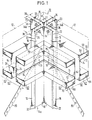
- a load-bearing element is a vertical support, which is differentiated according to the installation location of this support in the spatial framework according to outer wall supports 10 or 40 and pure inner wall supports 50. However, all advantageously consist of four identical individual profiles 14 and 15.
- a house corner with an outer wall support 10 can be seen from four identical individual profiles 14 in the form of an angle, which in this case are composed of an inner profile 14a.
- the angle profiles have flat legs 16 and 18 on the inside and outside, which have bevels 20 and 22, respectively.
- the legs 16 are located in the area of the outer wall and the uniform legs 18 are located in the inner wall area.
- Edge brackets 20 and 22 serve to stiffen the profiles 14a and 14b, the outer bends 20 also serving to fasten an outer skin 12.
- a support 10 modified with respect to the embodiment according to FIG. 1 with the angle profile 15 is shown in more detail in FIGS. 2 and 2a. The modification is that each leg of the angle 15 has a groove 19 drawn into the interior of the support 10.
- this channel 19 there is a spacer 26 or 27, which is described in more detail below, in such a way that a fastening means remains concealed within the channel 19 and a smooth leg contact surface for the horizontal support 60 with its webs 64 can be connected in this area.
- the principle is the same when using both angle profiles 14 or 15.
- the representation of the principle is simpler on the basis of the profile shape 14 and in practice the profile of the angle 15 is preferred because of the better design of the knots.
- the support 10 is composed of the four identical individual profiles 14a and 14b or 15a and 15b in such a way that a clear distance 36 remains between opposite legs 16 and 18, respectively.
- This distance 36 is particularly important between the legs 16 of an outside profile 14b or 15b and the legs 18 of an inside profile 14a or 15a. At this point, any metallic connection between the legs 16 and 18 over the distance 36 is avoided. This eliminates any metallic heat or cold bridge between the elements on the outside and the elements on the inside of a building constructed according to the invention.
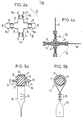
- FIGS. 5a and 5b An exemplary embodiment of how a mechanical connection is made available, which on the one hand avoids any heat flow in the connecting material and yet on the other hand ensures a good mechanical connection and strength, is shown therein.
- the illustrated embodiment shows in the inner part of the two representations a releasable mechanical connection 26 which can be used wherever elements on the outside with elements on the inside of the building are to be kept at the desired distance 36.
- This connection 26 consists of a non-metallic insulating body 28 without thermal conductivity and of sufficient strength. It can be hard rubber or a plastic body. In addition, a certain elasticity of the material is desired for sound insulation.
- Mechanical connecting elements for example threaded screw pins 30, are embedded in the body 28 so as to be resistant to torsion, tension and compression, axially aligned with one another. The torsional, tensile and compressive strength is achieved in that the screw pins 30 end inside the insulating and spacer body 28 in an anchor 32, which can be a simple radial widening, but also a star-shaped plate or the like.
- the two armatures 32 are in turn kept at a sufficient distance within the insulating and spacing body 28, in particular if these armatures 32 are made of metal in order to avoid any heat flow.
- the screw pins 30 are intended to protrude through corresponding openings in the legs 16 and 18 and the finished connection is made by nuts 34 during assembly.
- other detachable or non-detachable connections can also be provided instead of the screw connection.
- screw pins it is possible to provide hollow rivets or similar connecting elements.
- the insulating spacers 28 designed according to FIGS. 5a and 5b are arranged in all corners of the building and outer wall support elements to avoid heat flow between the outer parts, such as the legs 18, which run parallel to the outer skin 12, for example one above the other in a corner support 10 at the required intervals.
- simple, continuous metal spacers 27 can be used between the legs 16, which run transversely to the outer skin 12, in order to save costs. A heat flow need not be prevented in this area since both legs 16 are located in the same outer area of the spatial framework anyway.
- the connections of a diagonal band 80 shown in FIGS. 5a and 5b are used only at those connection points at which such a diagonal band 80 is actually to be connected, which of course applies to only a few such connection points. Therefore, this further embodiment is described in more detail below in connection with the diagonal bands. For most connection points, only the inner part of the spacer 28 according to FIGS. 5a and 5b without a wrapping diagonal band 80 is decisive.
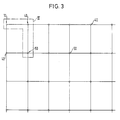
- FIG. 3 there can be three different supports seen in cross section.
- the support 10 already described in detail above is located in an outer corner of the building.
- Adjacent supports 40 are located in the flat area between the outer and inner skin and there are different supports 50 in the interior of the building.
- FIG. 4 the section marked in FIG. 3 with the three different types of supports is shown in more detail.
- the support 10 is located in a corner of the building.
- a further support 40 is located at a distance in the direction of the outer skin 12, it being noted that the representations according to FIGS. 3 and 4 are not true-to-scale representations of an actual building, but a schematic representation of the principle.
- the support 40 is also made up of four identical profile elements 14 as the support 10. However, while the support 10 in the corner of the building has a distance 36 in two intersecting planes or outer walls and is therefore set to a distance 36 in each connecting plane of the elements 14 , the distance 36 need only be maintained in the support 40 parallel to the outer skin 12 by inserting the insulating spacer elements 26 in the manner described above.
- the legs of the profiles 14 can be placed directly on top of one another and connected to one another by simple connecting elements 24 such as screws or rivets.
- a support 50 which is located entirely inside the building, is in any case constructed with legs which are connected directly to one another by connectors 24, as can be seen from the part below in the illustration in FIG. 4. Both supports 40 and 50 are statically connected with a diagonal band 80 in addition to the horizontal main beams not shown in this illustration.
- an inner support 50 is shown with the profile angles 15, which are connected directly and without spacing to rivets 24 in the channels 19. Like all other elements, the support 50 can be filled on the inside with insulating material 43.
- This infill of a prefabricated house skeleton is common and is only mentioned here for the sake of completeness. It is also known to close off the wall structure on the inside with a clamping plate 48.
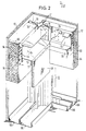
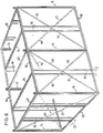
- Figure 6 is used to provide a schematic perspective overview of a composite spatial framework and to explain those levels that are also installed.
- leg purlins 100 At the bottom are all vertical supports (10, 40) in the wall area in leg purlins 100, which according to FIG. 7 are designed according to the distance 36 so that all feet 42 of the leg 10, 40 are adjusted and with the legs of the preferably U-profile leg purlins 100 in can be connected in a suitable manner.
- there are diagonal tension bands 80 between adjacent supports 10 and 40 which align the spatial truss when tensioning turnbuckles 82 and make it angularly rigid in all two wall levels.
- the space defined by the distance 36 and extending through each outer wall therefore not only enables an advantageous strict separation of the outer wall and inner wall structure, but also a suitable space for a diagonal bracing.
- Perforated flat strip material can preferably be used for the diagonal bracing.
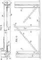
- FIGS. 6, 8, 9 and 10 there are vertically inserted dividing profiles 90 between the supports 10, 40 or 50 composed of four individual elements, which on the one hand serve to provide sufficient support for optionally insertable, soft lining material 94 and on the other hand one To provide additional static support for deriving forces that are introduced from the ceiling via cross members into the truss wall, as will be explained in more detail below.
- additional fastening surfaces are provided for the inner or outer skin.
- division profiles 90 are set in pairs in the area of an outer wall in the purlins 100, but according to the invention such that a distance 92 (FIGS. 6, 8, 9 and 10) is maintained in the direction of the longitudinal axis of each outer wall 12. With this spacing 92 in the area of the outer wall infill, thermal bridges are avoided due to the metal cross-sections of the dividing profiles 10 which are too closely adjacent and which penetrate the insulating material 94 or the air layer of the outer wall infill located in this area transversely thereto.
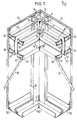
- a connection for a circumferential horizontal main beam 60 is provided with or without an additional connecting angle 76, which is in an embodiment 1 consists of angled profiles 62 arranged in pairs.
- Each profile 62 has a vertical web 64, on which a box profile 66 is folded at the top and bottom.
- the web 64 is bent at right angles to a flange 68, which is folded back parallel to the plane of the web 64 to an outer web 70.
- the box section 66 is finally completed by a transverse flange 72 with an edge 74.
- Such a profile 62 can be folded in one operation and offers sufficient static strength, whereby the connection between the edge 74 and the web can remain open.
- mechanical improvements in the section modulus of the carrier 60 can also be achieved by punching points or by attaching welding points. This can be achieved in a simple manner in the manufacture of profiles on the same machine, so that an increase in strength does not result in any particular manufacturing difficulties.
- secondary beams 84 can be inserted into the main beams 60, which are of uniform construction and have a smaller cross section.
- the main and secondary beams can, however, also be designed in accordance with a modification from FIGS. 2 and 8 in such a way that the U-legs end with outer webs 70 at low loads and have only one retracted edge 71.
- the retracted edge 71 is brought in a direction that is suitable for holding inserted insulation material.
- the webs 64 are connected when the horizontal main girders 60 with the supports 10, 40 or 50 at floor level are connected to the outer legs 16 and inner legs 18 of the supports 10 or 40, a distance being established between adjacent webs 64 of the same carrier 60, which is greater than the distance 36 is specified. This also ensures a separation of the outer and inner walls in the area of the horizontal beams and any thermal bridge is avoided.
- the insulating spacers 26 are used for this purpose, as shown by way of example in FIG. 1 on the left. In contrast to the illustration in FIG. 5b, these spacers 26 usually have an angular and not a round outline.
- a round outer configuration of the insulating body 28 in accordance with FIG. The insulating body 28 is then surrounded by a sleeve 31 which is normally not present and around which the end of the diagonal band 80 which is deformed into a loop 33 bears.
- the loop 33 is closed with fastening means 35.
- connection points for the diagonal band 80 are produced at the junctions with the spacers 26, for which spacers 27 made of metal can also be used, to the extent that this diagonal band 80 is required.
- the requirement follows from the static load and the necessary bracing. It will normally not be necessary to provide 10, 40 or 50 crossing diagonal bands in each field between supporting columns.
- the box-shaped profile 66 according to FIGS. 7 and 8 can each be provided with a dovetail-shaped or other-shaped longitudinal groove 67.
- the web 64 of the inner profile 62 can be connected to the inner leg 18 of the support 10 or 40 and the outer web 64 of an outer profile can be connected to the outer leg 16 of the support 10 or 40, so that the distance 36 is also preserved between the outer main beam 60.
- secondary girders 84 are inserted to form a load-bearing floor ceiling according to FIG. 8, which have the same structural shape as the main girder 60 and are laid on a suitable grid scale and are connected to the main girders 60.
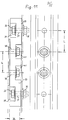
- 11 and 12 show a further modified embodiment of the outer wall region part from the insulating body 28 separating the inner wall region parts without thermal conductivity and with sufficient strength. All lines previously described are identified by the same reference numbers.
- This modified spacer 28 can be used according to FIG. 11 in elevation or according to FIG. 12 in the plan in the support area of the outer skin. 11 can also be seen as an example of a connection in the horizontal beam area.
- the spacer 28 consists of a plywood board 29 and is inserted between the respective metal parts between the outer wall area 12 and the inner wall area at a distance 36.
- the metal parts expediently have a row of holes with a fixed, predetermined distance “L” of, for example, 60 mm. Accordingly, the board 29 also has a perforation at a distance “L”.
- a screw bolt 33 is inserted through a first bore 31, which is provided on the outside with a nut 35, while the screw head of the bolt 33 is located in a recess 37.
- Another bolt 39 is offset by the dimension “L” from the outside with its bolt head in a recess 41 such that it can be provided with a nut 43 (FIG. 12). This series can be continued alternately. In any case, a thermal bridge is easily avoided.
Landscapes
- Engineering & Computer Science (AREA)
- Architecture (AREA)
- Physics & Mathematics (AREA)
- Electromagnetism (AREA)
- Civil Engineering (AREA)
- Structural Engineering (AREA)
- Building Environments (AREA)
Description
- Die vorliegende Erfindung betrifft ein aus Einzelelementen bestehendes Raumfachwerk aus Metall zum Errichten von Gebäuden. Es ist bekannt, Raumfachwerke aus Metallprofilen zu errichten. Ein derartiger Vorschlag ist beispielsweise aus der Deutschen Offenlegungsschrift DE-OS 31 30 427 bekannt. Ein anderer Vorschlag geht aus der US-PS 4 205 497 hervor.
- In der FR-A-21 84 676 ist ein Bauskelett für Bauten verschiedener Art beschrieben, das aus vierkantigen, metallischen, profilierten Säulen besteht, an denen mittels Knotenblechen Querbalken angeschlagen werden können. Es ergibt sich hierbei allerdings eine direkte metallische Verbindung ohne isolierende Zwischenschicht, womit eine Wärmebrücke zwischen der Innen- und Aussenhaut des Gebäudes gebildet wird. In die Profilierungsleisten können Füllstücke, vorzugsweise aus Hartgummi, eingeschlagen werden, die dann zum Abstützen und zum Befestigen von Wandteilen, Türrahmen, Fenstern und dergleichen dienen. Diese eingeschlagenen Füllstücke übernehmen dabei keine tragende Funktion.
- Während bei den ursprünglichen aus Holz gefertigten Bauskeletten eine gute Wärmedämmung zwischen Aussen- und Innenhaut vom verwendeten Material her gewährleistet ist, weisen die vor allem in den Vereinigten Staaten aus den Holzbauskeletten aus Kostengründen weiterentwickelten Metallskelettmontagehäuser, bei denen im wesentlichen das Raumfachwerk aus Holz durch Metallprofile ersetzt wurde, den Mangel auf, dass diese Fertighäuser nicht in allen Klimazonen verwendbar sind. Die Metallprofile bilden Wärmebrücken zwischen der Innen- und Aussenhaut, was sowohl dann nachteilig ist, wenn die Häuser wegen hoher Aussentemperaturen innen klimatisiert oder wegen niedriger Aussentemperaturen innen beheizt werden müssen. Nur in ausgeglichenen gemässigten Zonen lassen sich die bisher bekannten Fertighäuser mit Metallskelett verwenden. In allen anderen Zonen ist der Betrieb dieser Fertighäuser mit hohem Energieaufwand verbunden. Es treten auch durch die thermischen Belastungsschwankungen nach einer gewissen Benutzungsdauer zu schnell Bauschäden auf. Es bilden sich Risse und Feuchtigkeit dringt in das Bauwerk ein.
- Es ist deshalb Aufgabe der vorliegenden Erfindung, ein Metallskelett verfügbar zu machen, das für beliebige Gebäudehöhen wie ein- oder mehrgeschossige Bauten, für verschiedene Verwendungszwecke, zum Wohnen, zum Arbeiten, für Lagerhaltung, für Sport, Spiel oder Freizeit, für private oder öffentliche Zwecke alle Varianten von Bauformen und Grundrissen zulässt und das eine gute Isolierung ermöglicht.
- Diese Aufgabe wird erfindungsgemäss mit den Merkmalen des Anspruches 1 gelöst.
- Vorteilhafte Weiterbildungen sind in den abhängigen Ansprüchen angegeben.
- Die Erfindung betrifft ferner einen isolierenden Abstandhalter zur Verwendung in dem erfindungsgemässen Raumfachwerk.
- Es handelt sich um eine Bauweise, bei der bewusst die Aussenhaut nicht als tragendes Element mitherangezogen wird. Man erreicht durch dieses Prinzip der reinen Skelettbauweise die leichte Anpassbarkeit an verschiedene Gestaltungswünsche, was an sich bekannt ist. Nur das Skelett hat statische Funktionen.
- Mit der hierdurch erreichten prinzipiellen Trennung von Aussen- und Innenhaut wird erfindungsgemäss ein vielseitig verwendbares Metallskelett geschaffen, bei dem alle Probleme des Wärmeübergangs zwischen innen und aussen überwunden sind. Das bezieht sich sowohl auf die Wärmeisolierung oder -dämmung als auch auf die Vermeidung von Spannungen und von Kondenswasser. Das Skelett verwendet wenige, nämlich im wesentlichen drei Element- und Profilarten und lässt dadurch eine rationelle Aufteilung der Vorfertigung in einem stationären Betrieb, leichten Transport zum Verwendungsort und eine kostengünstigere Montage zu.
- Ein weiterer wichtiger Vorteil für diese Art der Montagebauweise ist es, dass leicht statische Einzelnachweise für die beliebigen Gestaltungsweisen möglich sind. Das vorliegende Skelettsystem ist an keine allgemeine Genehmigung gebunden, die die Vielfalt der Gestaltungsmöglichkeiten einengt. Vielmehr wird ein Stab- und Tragwerk vorgegeben, für das leicht und schnell ein statischer Nachweis im individuellen Einzelfall möglich ist, da die Wände keine statischen, sondern nur isolierende Funktionen haben.
- Das Skelett besteht aus kostengünstig herstellbaren Blechprofilen, die einheitlich vorgefertigt werden können. Da kein Raster vorgegeben zu werden braucht, können diese angeordnet werden, um sich auf diese Weise den statischen Erfordernissen anzupassen, ohne dass statisch unterschiedlich tragfähige Profile auf Vorrat gehalten werden müssen.
- Weitere Einzelheiten, Merkmale und Vorteile der Erfindung ergeben sich aus der nachfolgenden Beschreibung eines in der Zeichnung dargestellten Ausführungsbeispiels mit Abwandlungen.
Es zeigen: - Fig. 1 eine schematische Perspektive einer Eckausbildung an einer Aussenseite,
- Fig. 2 eine gegenüber Fig. 1 abgewandelte Ausführungsform der verwendeten Stütze,
- Fig. 2a einen schematischen Schnitt durch die gemäss Fig. 2 abgewandelte Stütze,
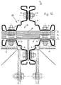
- Fig. 3 einen schematischen Querschnitt durch eine Deckenebene,
- Fig. 4 einen schematischen Querschnitt und eine Draufsicht eines in Fig. 3 mit «IV» bezeichneten Feldes mit Stützen im Aussen- und Innenwandbereich,
- Fig. 4a eine Innenwandstütze mit dem gemäss Fig. 2 abgewandelten Profil
- Fig. 5a und Fig. 5b ein Detail aus Fig. 1 und 2a in zwei Darstellungsebenen,
- Fig. 6 eine schematische perspektivische Darstellung eines aus den Elementen aufgebauten räumlichen Fachwerks,
- Fig. 7 eine gegenüber Figur 1 abgewandelte Ausführungsform,
- Fig. 8 im Detail eine Einbindung eines zwischen Stützen anordbaren Deckenträgers,
- Fig. 9 einen Querschnitt durch einen Wandabschnitt,
- Fig. 10 einen Aufriss durch denselben Wandabschnitt und
- Fig. 11 und 12 eine abgewandelte Ausführungsform eines isolierenden Abstandhalters.
- Ein räumliches Fachwerk-Skelett wird aus vorgefertigten Metall-Profil- und Flachmaterialelementen aufgebaut. Ein tragendes Element ist eine vertikale Stütze, die je nach Einbauort dieser Stütze im räumlichen Fachwerk nach Aussenwandstützen 10 oder 40 und reinen Innenwandstützen 50 unterschieden wird. Alle setzen sich jedoch vorteilhafterweise aus jeweils vier gleichen Einzelprofilen 14 und 15 zusammen.
- In Figur 1 ist eine Hausecke mit einer Aussenwandstütze 10 aus vier gleichen Einzelprofilen 14 in Form eines Winkels erkennbar, die sich in diesem Fall aus einem Innenprofil 14a zusammensetzen. Im dargestellten Beispiel haben die Winkelprofile innen und aussen ebene Schenkel 16 und 18, welche Abkantungen 20 bzw. 22 aufweisen. Die Schenkel 16 befinden sich im Bereich der Aussenwand und die gleichförmigen Schenkel 18 im Innenwandbereich. Zur Aussteifung der Profile 14a und 14 b dienen Randabwinklungen 20 bzw. 22, wobei die aussenliegenden Abwinklungen 20 zugleich der Befestigung einer Aussenhaut 12 dienen. Eine gegenüber der Ausführungsform gemäss Figur 1 abgewandelte Stütze 10 mit dem Winkelprofil 15 ist in Figuren 2 und 2a näher dargestellt. Die Abwandlung besteht darin, dass jeder Schenkel des Winkels 15 eine in das Innere der Stütze 10 eingezogene Rinne 19 aufweist. Im Bereich dieser Rinne 19 befindet sich ein nachstehend näher beschriebener Abstandhalter 26 oder 27 derart, dass ein Befestigungsmittel innerhalb der Rinne 19 verdeckt bleibt und eine glatte Schenkelauflagefäche für den in diesem Bereich anschliessbaren Horizontalträger 60 mit ihren Stegen 64 entsteht. Das Prinzip ist bei der Verwendung beider Winkelprofile 14 oder 15 gleich. Die Darstellung des Prinzips ist anhand der Profilform 14 einfacher und in der Praxis wird wegen der besseren Ausbildung der Knoten das Profil des Winkels 15 bevorzugt.
- Die Stütze 10 ist in jedem Fall aus den vier gleichen Einzelprofilen 14a und 14b oder 15a und 15b so zusammengesetzt, dass zwischen gegenüberliegenden Schenkel 16 bzw. 18 ein deutlicher Abstand 36 bleibt. Dieser Abstand 36 ist besonders zwischen den Schenkeln 16 eines aussen befindlichen Profils 14b oder 15b und den Schenkeln 18 eines innen stehenden Profils 14a oder 15a wesentlich. Es wird an dieser Stelle jede metallische Verbindung zwischen den Schenkeln 16 und 18 über den Abstand 36 vermieden. Damit wird jede metallische Wärme- oder Kältebrücke zwischen den Elementen der Aussenseite und den Elementen der Innenseite eines erfindungsgemäss errichteten Bauwerks eliminiert.
- Wie diese Besonderheit im einzelnen gestaltet werden kann, geht im Detail aus den Figuren 5a und 5b hervor. Hierin ist zunächst ein Ausführungsbeispiel dargestellt, wie eine mechanische Verbindung verfügbar gemacht wird, die einerseits jeden Wärmefluss im Verbindungsmaterial vermeidet und dennoch andererseits eine gute mechanische Verbindung und Festigkeit gewährleistet. Das dargestellte Ausführungsbeispiel zeigt im inneren Teil der beiden Darstellungen eine lösbare mechanische Verbindung 26, die überall dort einsetzbar ist, wo Elemente der Aussenseite mit Elementen der Innenseite des Bauwerks auf den erwünschten Abstand 36 zu halten sind.
- Diese Verbindung 26 besteht aus einem nichtmetallischen Isolierkörper 28 ohne Wärmeleitfähigkeit und von genügender Festigkeit. Es kann Hartgummi- oder ein Kunststoffkörper sein. Zusätzlich ist zur Schalldämmung eine gewisse Elastizität des Materials erwünscht. In dem Körper 28 sind verdreh-, zug- und druckfest mechanische Verbindungselemente, beispielsweise mit Gewinde versehene Schraubstifte 30, axial zueinander ausgerichtet eingebettet. Die Dreh-, Zug- und Druckfestigkeit wir dadurch erzielt, dass die Schraubstifte 30 innen im Isolier- und Abstandskörper 28 in einem Anker 32 enden, der eine einfache radiale Verbreiterung, aber auch eine sternförmige Platte oder ähnliches sein kann. Die beiden Anker 32 werden innerhalb des Isolier- und Abstandskörpers 28 ihrerseits auf genügenden Abstand gehalten, insbesondere wenn diese Anker 32 aus Metall bestehen, um jeglichen Warmefluss zu vermeiden. Die Schraubstifte 30 sind zum Durchragen durch entsprechende Öffnungen in den Schenkeln 16 und 18 bestimmt und die fertige Verbindung wird beim Montieren durch Muttern 34 hergestellt. Es können aber auch andere lösbare oder unlösbare Verbindungen statt der Verschraubung vorgesehen werden. Beispielsweise ist es möglich, statt Schraubstiften Hohlnieten oder ähnliche Verbindungselemente vorzusehen.
- Die gemäss Figuren 5a und 5b ausgestalteten isolierenden Abstandhalter 28 sind in allen Gebäudeecken und Aussenwandtragelementen zur Vermeidung von Wärmefluss zwischen den parallel zur Aussenhaut 12 verlaufenden aussen liegenden Teilen wie den Schenkeln 18 angeordnet und zwar beispielsweise übereinander in einer Eckstütze 10 in erforderlichen Abständen. In gleichen Abständen können zwischen den Schenkeln 16 untereinander, die quer zur Aussenhaut 12 verlaufen, einfache durchgehend metallische Abstandhalter 27 verwendet werden, um Kosten zu sparen. In diesem Bereich braucht ein Wärmefluss nicht verhindert zu werden, da sich beide Schenkel 16 ohnehin im selben Aussenbereich des räumlichen Fachwerks befinden. Die in den Figuren 5a und 5b dargestellten Anschlüsse eines Diagonalbandes 80 werden nur an jenen Verbindungsstellen benutzt, an denen tatsächlich ein derartiges Diagonalband 80 anzuschliessen ist, was natürlich für nur wenige derartige Verbindungsstellen zutrifft. Deshalb wird diese weitere Ausgestaltung nachstehend in Verbindung mit den Diagonalbändern näher beschrieben. Für die meisten Verbindungspunkte ist nur der innere Teil des Abstandhalters 28 gemäss Figuren 5a und 5b ohne umschlingendes Diagonalband 80 massgebend.
- Wie aus der schematischen Darstellung von Fig. 3 hervorgeht, kann es im Querschnitt gesehen drei verschiedene Stützen geben. Die zuvor bereits ausführlich beschriebene Stütze 10 befindet sich in einer äusseren Gebäudeecke. Benachbarte Stützen 40 befinden sich im ebenen Bereich zwischen Aussen- und Innenhaut und im Gebäudeinneren befinden sich hierzu unterschiedliche Stützen 50. In Fig. 4 ist der in Fig. 3 markierte Abschnitt mit den drei unterschiedlichen Stützentypen näher dargestellt.
- Links oben in dieser Darstellung befindet sich mit den bereits erläuterten Elementen die Stütze 10 in einer Gebäudeecke. In Richtung der Aussenhaut 12 befindet sich in einem Abstand eine weitere Stütze 40, wobei anzumerken ist, dass es sich bei den Darstellungen gemäss Fig. 3 und 4 nicht um massstabgetreue Darstellungen eines tatsächlichen Gebäudes handelt, sondern um eine schematische Darstellung des Prinzips.
- Die Stütze 40 ist ebenfalls aus vier gleichen Profilelementen 14 aufgebaut, wie die Stütze 10. Während jedoch die Stütze 10 in der Gebäudeecke je einen Abstand 36 in zwei sich rechtwinklig kreuzenden Ebenen oder Aussenwänden aufweist und deshalb in jeder Verbindungsebene der Elemente 14 auf Abstand 36 gesetzt ist, braucht in der Stütze 40 der Abstand 36 nur parallel zur Aussenhaut 12 durch Einfügen der isolierenden Abstandelemente 26 in der zuvor beschriebenen Weise aufrechterhalten zu werden. In der dazu quer verlaufenden Zusammenfügungsebene können die Schenkel der Profile 14 unmittelbar aufeinandergesetzt und durch einfache Verbindungselemente 24 wie Schrauben oder Nieten miteinander verbunden werden. Eine völlig im Inneren des Gebäudes befindliche Stütze 50 ist ohnehin mit durch Verbinder 24 direkt aneinandergefügte Schenkel aufgebaut, wie dies aus dem darunterliegenden Teil in der Darstellung der Fig. 4 hervorgeht. Beide Stützen 40 und 50 sind mit einem Diagonalband 80 statisch zusätzlich zu den in dieser Darstellung nicht eingezeichneten Horizontal-Hauptträgern verbunden.
- In der zusätzlichen Darstellung von Figur 4a ist eine Innenstütze 50 mit den Profilwinkeln 15 dargestellt, welche direkt und ohne Abstand mit Nieten 24 in den Rinnen 19 verbunden sind. Die Stütze 50 kann wie alle anderen Elemente innen mit Isoliermaterial 43 gefüllt sein.
- Überall und insbesondere in dem durch den Abstand 36 vorgegebenen Raum kann eine isolierende Innenfüllung 44 aus geeignetem Dämmaterial vorgesehen werden, die zu der Innenseite mit einer Dampfsperrschicht 46 versehen ist. Diese Ausfachung eines Fertighausskelettes ist üblich und wird hier nur der Vollständigkeit halber erwähnt. Ebenso bekannt ist es, den Wandaufbau nach innen mit einer Pressspannplatte 48 abzuschliessen.
- Die Figur 6 dient dazu, einen schematischen perspektivischen Überblick über ein zusammengesetztes räumliches Fachwerk zu geben und um jene Ebenen zu erläutern, die zusätzlich eingebaut werden.
- Unten stehen sämtliche vertikalen Stützen (10, 40) im Wandbereich in Fusspfetten 100, die gemäss Figur 7 entsprechend des Abstandes 36 so ausgelegt werden, dass alle Füsse 42 der Stutzen 10, 40 eingestellt und mit den Schenkeln der bevorzugt U-profilförmigen Fusspfetten 100 in geeigneter Weise verbunden werden können. Im durch den Abstand 36 vorgegebenen Zwischenraum verlaufen zwischen benachbarten Stützen 10 bzw. 40 diagonal Zugbänder 80, welche beim Spannen von Spannschlössern 82 das räumliche Fachwerk ausrichten und in allen zwei Wandebenen winkelsteif machen. Der durch den Abstand 36 vorgegebene überall durch jede Aussenwand sich erstreckende Zwischenraum ermöglicht deshalb nicht nur eine vorteilhafte strikte Trennung von Aussenwand- und Innenwandaufbau, sondern auch einen geeigneten Freiraum für eine Diagonalverstrebung. Bevorzugt kann gelochtes Flachbandmaterial für die Diagonalverstrebung benutzt werden.
- Die nachfolgende Beschreibung bezieht sich vornehmlich auf die Darstellungen in den Figuren 6 bis 10. Es wird jedoch teilweise zugleich auf noch nicht näher beschriebene Einzelheiten der vorausgehenden Figuren eingegangen. Wie aus Figuren 6, 8 9 und 10 hervorgeht, befinden sich zwischen den aus jeweils vier Einzelelementen zusammengesetzten Stützen 10, 40 oder 50 vertikal eingesetzte Teilungsprofile 90, die einerseits dazu dienen, wahlweise einlegbarem, weichem Auskleidungsmaterial 94 genügend Halt zu bieten und um andererseits eine zusätzliche statische Unterstützung zum Ableiten von Kräften zu bieten, die aus der Decke über Querträger in die Fachwerkwand eingeleitet werden, wie nachstehend noch näher zu erläutern sein wird. Ausserdem werden zusätzliche Befestigungsflächen für die Innen- oder Aussenhaut dargeboten. Diese Teilungsprofile 90 werden im Bereich einer Aussenwand in den Fusspfetten 100 paarweise eingestellt, jedoch erfindungsgemäss so, dass in Richtung der Längsachse jeder Aussenwand 12 ein Abstand 92 (Fig. 6, 8, 9 und 10) eingehalten wird. Mit diesem Abstand 92 wird im Bereich der Aussenwandausfachung vermieden, dass durch zu eng benachbarte Metallquerschnitte der Teilungsprofile 10, welche das Dämmaterial 94 oder die in diesem Bereich befindliche Luftschicht der Aussenwandausfachung quer zu dieser durchsetzen, Wärmebrücken entstehen.
- Dort wo oben an den Stützen 10, 40 oder 50 die Diagonalverstrebungen 80 in Befestigungsöffnungen 78 anschliessen können, wird mit oder ohne zusätzlichen Verbindungswinkel 76 eine Verbindung für einen umlaufenden Horizontalhauptträger 60 vorgesehen, der in einer Ausfuhrungsform gemäss Fig. 1 aus paarweise angeordneten, abgewinkelten Profilen 62 besteht. Jedes Profil 62 weist einen vertikalen Steg 64, dem oben und unten ein Kastenprofil 66 angefaltet ist, auf. Zu diesem Zweck wird der Steg 64 rechtwinklig zu einem Flansch 68 abgeknickt, welcher parallel zur Ebene des Steges 64 zu einem Aussensteg 70 zurückgefaltet wird. Das Kastenprofil 66 wird schliesslich durch einen Querflansch 72 mit Kante 74 vervollständigt. Ein solches Profil 62 lässt sich in einem Arbeitsgang falzen und bietet eine genügende statische Festigkeit.Hierbei kann die Verbindung zwischen der Kante 74 mit dem Steg offen bleiben. Es lassen sich aber auch durch Einstanzen von Punkten oder durch Anbringen von Schweisspunkten mechanische Verbesserungen des Widerstandsmomentes des Trägers 60 erzielen. Diese kann bei der Profilherstellung in einfacher Weise auf derselben Maschine erreicht werden, so dass eine Steigerung der Festigkeit keine besonderen Herstellschwierigkeiten zur Folge hat.
- In die Hauptträger 60 lassen sich zur Bildung einer Geschossdecke Nebenträger 84 einlegen, die gleichförmig aufgebaut sind und einen kleineren Querschnitt aufweisen. Die Haupt- und Nebenträger können jedoch auch gemäss einer Abwandlung aus Figuren 2 und 8 so ausgeführt werden, dass bei geringen Belastungen die U-Schenkel mit Aussenstegen 70 enden und nur eine eingezogene Kante 71 aufweisen. Die eingezogene Kante 71 wird hierbei in eine Richtung gebracht, die geeignet ist, eingelegtes Dämmaterial zu halten.
- Die Stege 64 werden beim Zusammenfügen der Horizontalhauptträger 60 mit den Stützen 10, 40 oder 50 in Stockwerkshöhe mit den Aussenschenkeln 16 und Innenschenkeln 18 der Stützen 10 oder 40 verbunden, wobei sich zwischen benachbarten Stegen 64 desselben Trägers 60 ein Abstand einstellt, der von dem Abstand 36 vorgegeben ist. Damit ist auch im Bereich der Horizontalträger eine Trennung von Aussen- und Innenwand gewährleistet und es wird jede Wärmebrücke vermieden.
- Sofern aus statischen Gründen eine mechanische Verbindung benachbarter Stege 64 erforderlich ist, werden hierfür die isolierenden Abstandshalter 26 benutzt, wie links beispielhaft in Figur 1 eingezeichnet. Diese Abstandshalter 26 haben gewöhnlicherweise in Abweichung zur Darstellung von Figur 5b einen eckigen und nicht einen runden Umriss. Lediglich an solchen Knoten, an denen ein überall nur schematisch eingezeichnetes Diagonalband 80 mittig angeschlossen werden soll, was in der Praxis gegenüber der schematischen Darstellung in der Patentzeichnung geschieht, kann eine runde Aussenfiguration des Isolierkörpers 28 gemäss Figur 5b zweckmässig sein. Der Isolierkörper 28 wird dann von einer normalerweise nicht vorhandenen Hülse 31 umgeben, um die sich das zu einer Schlaufe 33 verformte Ende des Diagonalbandes 80 anlegt. Mit Befestigungsmitteln 35 wird die Schlaufe 33 geschlossen. Auf diese Weise entstehen an den Verbindungsstellen mit den Abstandshaltern 26, für die auch Abstandshalter 27 aus Metall im Innenbereich genommen werden können, Anschlussstellen für das Diagonalband 80, soweit dieses Diagonalband 80 erforderlich ist. Das Erfordernis folgt aus der statischen Belastung und der notwendigen Aussteifung. Normalerweise wird es nicht nötig sein, in jedem Feld zwischen tragenden Stützen 10, 40 oder 50 sich kreuzende Diagonalbänder vorzusehen.
- Zur weiteren Verbesserung der Steifigkeit des räumlichen Fachwerks kann das kastenförmige Profil 66 gemäss Figuren 7 und 8 jeweils mit einer schwalbenschwanzförmigen oder andersförmigen Längsnut 67 versehen werden. In jedem Fall lässt sich der Steg 64 des innen liegenden Profils 62 mit dem innen liegenden Schenkel 18 der Stütze 10 oder 40 verbinden und der aussen liegende Steg 64 eines aussen liegenden Profils mit dem äusseren Schenkel 16 der Stütze 10 oder 40, so dass der Abstand 36 auch zwischen dem aussen verlaufenden Hauptträger 60 erhalten bleibt.
- Zwischen den nach innen weisenden Schenkel 66 des Horizontalhauptträgers 62 werden zur Ausbildung einer tragenden Geschossdecke gemäss Fig. 8 Nebenträger 84 eingelegt, welche in ihrer Bauform dem Hauptträger 60 entsprechen und im geeigneten Rastermassstab verlegt sowie mit den Hauptträgern 60 verbunden werden.
- Es lassen sich auf diese Weise ein- oder mehrgeschossige Bauwerke errichten, wobei die Stutzen 10, 40 und 50 in ihren Achsen nach oben fortgeführt werden.
- In Fig. 11 und 12 ist eine weitere abgewandelte Ausführungsform des Aussenwandbereichsteil von den Innenwandbereichsteilen trennenden Isolierkörpers 28 ohne Wärmeleitfähigkeit und von genügender Festigkeit dargestellt. Alle zuvor bereits beschriebenen Zeilen sind mit denselben Bezugszahlen bezeichnet. Dieser abgewandelte Abstandshalter 28 kann gemäss Fig. 11 in Aufriss oder gemäss Fig. 12 im Grundriss im Stützenbereich der Aussenhaut eingesetzt werden. Die Fig. 11 kann auch als Beispiel für eine Verbindung im Horizontalträgerbereich angesehen werden. Der Abstandshalter 28 besteht aus einem Sperrholzbrett 29 und wird zwischen die jeweiligen Metallteile zwischen dem Aussenwandbereich 12 und dem Innenwandbereich im Abstand 36 eingefügt.
- Zweckmässigerweise erhalten die Metallteile eine Lochreihe mit einem festen vorgegebenen Abstand «L» von beispielsweise 60 mm. Dementsprechend erhält auch das Brett 29 eine Lochung im Abstand «L».Durch eine erste Bohrung 31 ist ein Schraubbolzen 33 gesteckt, welcher aussenseitig mit einer Mutter 35 versehen ist, während der Schraubkopf des Bolzens 33 sich in einer Ausnehmung 37 befindet. Um das Mass «L» versetzt wird ein weiterer Schraubbolzen 39 von der Aussenseite her mit seinem Bolzenkopf in einer Ausnehmung 41 so durchgesteckt, dass er mit einer Mutter 43 (Fig. 12) versehen werden kann. Diese Reihe kann alternierend fortgesetzt werden. In jedem Fall wird eine Wärmebrücke auf einfache Weise vermieden.
- Die Schrauben werden zueinander um das vorgegebene Lochmass L versetzt angeordnet. Dennoch ergibt sich eine steife Verbindung. Die auftretenden Momente gleichen sich aus; da die Flächen der Teile aus den unterschiedlichen Materialien Holz und Metall aufeinander aufliegen, treten keine Verspannungen auf. Es ist eine leichte Montierbarkeit gewährleistet.
Claims (22)
Priority Applications (1)
| Application Number | Priority Date | Filing Date | Title |
|---|---|---|---|
| AT85904441T ATE44063T1 (de) | 1984-08-20 | 1985-08-20 | Metall-raumfachwerk aus einzelelementen zum errichten von gebaeuden. |
Applications Claiming Priority (2)
| Application Number | Priority Date | Filing Date | Title |
|---|---|---|---|
| DE3430612 | 1984-08-20 | ||
| DE19843430612 DE3430612A1 (de) | 1984-08-20 | 1984-08-20 | Metall-raumfachwerk aus einzelelementen zum errichten von gebaeuden |
Publications (2)
| Publication Number | Publication Date |
|---|---|
| EP0193571A1 EP0193571A1 (de) | 1986-09-10 |
| EP0193571B1 true EP0193571B1 (de) | 1989-06-14 |
Family
ID=6243479
Family Applications (1)
| Application Number | Title | Priority Date | Filing Date |
|---|---|---|---|
| EP85904441A Expired EP0193571B1 (de) | 1984-08-20 | 1985-08-20 | Metall-raumfachwerk aus einzelelementen zum errichten von gebäuden |
Country Status (4)
| Country | Link |
|---|---|
| US (1) | US4742665A (de) |
| EP (1) | EP0193571B1 (de) |
| DE (2) | DE3430612A1 (de) |
| WO (1) | WO1986001242A1 (de) |
Families Citing this family (58)
| Publication number | Priority date | Publication date | Assignee | Title |
|---|---|---|---|---|
| FR2613403A1 (fr) * | 1987-04-03 | 1988-10-07 | Bretzner Michel | Pilier, notamment pour constructions a ossature bois et constructions faisant usage de tels piliers |
| US5513473A (en) * | 1992-01-06 | 1996-05-07 | Sucre F.; Alfredo | Prefabricated building system |
| GB9218957D0 (en) * | 1992-09-08 | 1992-10-21 | Perks Arthur T | Graviationally locked structural joint |
| US5642594A (en) * | 1993-10-05 | 1997-07-01 | Sucre F; Alfredo | Prefabricated building system |
| WO1997032093A1 (en) * | 1996-03-01 | 1997-09-04 | Bhp Steel (Jla) Pty. Ltd. | Insulation system |
| US5740648A (en) * | 1996-05-14 | 1998-04-21 | Piccone; Francesco | Modular formwork for concrete |
| US5809726A (en) * | 1996-08-21 | 1998-09-22 | Spude; Gerald T. | Foundation construction system |
| DE19636802A1 (de) * | 1996-09-11 | 1998-03-12 | Ernst Koller | Gebäudeskelett |
| CA2271601C (en) | 1997-10-17 | 2003-06-17 | The Global Engineering Trust | Modular formwork elements and assembly |
| WO1999049146A1 (en) * | 1998-03-23 | 1999-09-30 | Cote Claude | Wall structure |
| US6694692B2 (en) * | 1998-10-16 | 2004-02-24 | Francesco Piccone | Modular formwork elements and assembly |
| CA2315401A1 (en) | 1999-08-13 | 2001-02-13 | Alfredo J. Sucre F. | Corner studs for prefabricated building systems |
| US6421972B1 (en) | 2000-04-27 | 2002-07-23 | I Mozaic Trust | Modular wall component with insulative thermal break |
| US6698710B1 (en) | 2000-12-20 | 2004-03-02 | Portland Cement Association | System for the construction of insulated concrete structures using vertical planks and tie rails |
| US6837016B2 (en) * | 2001-08-30 | 2005-01-04 | Simmons Robert J | Moment-resistant building frame structure componentry and method |
| US20050055969A1 (en) * | 2002-03-18 | 2005-03-17 | Simmons Robert J. | Building frame structure |
| US6802169B2 (en) * | 2002-03-18 | 2004-10-12 | Robert J. Simmons | Building frame structure |
| US20040200178A1 (en) * | 2003-04-08 | 2004-10-14 | Simmons Robert J. | Matrix frame/panel skin building structure |
| GR1006183B (el) * | 2005-10-07 | 2008-12-08 | Δημητριος Γεωργιου Φαης | Μεθοδος κατασκευης φεροντα οργανισμου (σκελετου) προς ανεγερση κτιριων, με συνδεση μεταξυ τους γραμμικων φορεων ορθογωνικης διατομης και πρισματικης μορφης. |
| FR2906277B1 (fr) * | 2006-09-22 | 2008-12-12 | Apr Entpr Sarl | Procede de construction d'un batiment d'habitation a ossature porteuse metallique et batiment obtenu |
| CN101680234A (zh) * | 2007-04-02 | 2010-03-24 | Cfs混凝土模板系统公司 | 在混凝土结构体上提供衬里的方法和设备 |
| CA2816303C (en) | 2007-11-09 | 2015-06-02 | Cfs Concrete Forming Systems Inc. | Connector components for form-work systems and methods for use of same |
| WO2009092158A1 (en) * | 2008-01-21 | 2009-07-30 | Octaform Systems Inc. | Stay-in-place form systems for windows and other building openings |
| DE102008028672A1 (de) * | 2008-06-17 | 2009-12-24 | Hoesch Schwerter Profile Gmbh | Konstruktionselement für Bauten, einschließlich transportabler Bauten |
| US8943774B2 (en) * | 2009-04-27 | 2015-02-03 | Cfs Concrete Forming Systems Inc. | Methods and apparatus for restoring, repairing, reinforcing and/or protecting structures using concrete |
| EP2376724B1 (de) | 2009-01-07 | 2016-11-09 | CFS Concrete Forming Systems Inc. | Verfahren und vorrichtung zum wiederherstellen, reparieren, verstärken und/oder schützen von strukturen mithilfe von beton |
| CA2751610C (en) | 2009-02-18 | 2015-06-09 | Cfs Concrete Forming Systems Inc. | Clip-on connection system for stay-in-place form-work |
| CA2804361C (en) | 2010-07-06 | 2014-04-08 | Cfs Concrete Forming Systems Inc. | Push on system for restoring, repairing, reinforcing, protecting, insulating and/or cladding structures |
| WO2013075251A1 (en) | 2011-11-24 | 2013-05-30 | Cfs Concrete Forming Systems Inc. | Stay-in place formwork with engaging and abutting connections |
| WO2013075250A1 (en) | 2011-11-24 | 2013-05-30 | Cfs Concrete Forming Systems Inc. | Stay-in-place formwork with anti-deformation panels |
| CA2859608C (en) | 2012-01-05 | 2018-01-23 | Cfs Concrete Forming Systems Inc. | Systems for restoring, repairing, reinforcing, protecting, insulating and/or cladding structures with locatable stand-off components |
| US10151119B2 (en) | 2012-01-05 | 2018-12-11 | Cfs Concrete Forming Systems Inc. | Tool for making panel-to-panel connections for stay-in-place liners used to repair structures and methods for using same |
| EP3243978B1 (de) | 2012-01-05 | 2023-07-12 | CFS Concrete Forming Systems Inc. | Verbindungen zwischen platten für stationäre futter zur reparatur von strukturen |
| CA2763058C (en) | 2012-01-05 | 2014-10-14 | Cascadia Windows Ltd. | Thermally insulative spacer and methods involving use of same |
| US9109874B2 (en) | 2012-12-29 | 2015-08-18 | Conxtech, Inc. | Modular, six-axis-adjustable, concrete-pour form-structure system |
| US9803380B2 (en) | 2013-01-24 | 2017-10-31 | Conxtech, Inc. | Plural-story, pipe-support frame system with modular, removably attachable lateral-worker-support scaffolding |
| MX361561B (es) | 2013-01-27 | 2018-12-11 | Conxtech Inc | Sistema de manejo de componente de construccion por recoleccion y alineacion de pilas, de inscripcion por saliente, de labor secuencial, de doble funcion. |
| WO2014163964A1 (en) | 2013-03-13 | 2014-10-09 | Conxtech, Inc. | Modular, faceted, block-and-shell node system for connecting elongate frame elements |
| US9783991B2 (en) | 2013-12-06 | 2017-10-10 | Cfs Concrete Forming Systems Inc. | Structure cladding trim components and methods for fabrication and use of same |
| KR20170010744A (ko) | 2014-01-13 | 2017-02-01 | 콘스테크, 아이엔씨. | 클래스프-러그 시스템 |
| CA2943642C (en) | 2014-04-04 | 2022-07-19 | Cfs Concrete Forming Systems Inc. | Liquid and gas-impermeable connections for panels of stay-in-place form-work systems |
| DK178478B1 (da) * | 2014-11-14 | 2016-04-11 | Supply Holding Aps | System til konstruktion af en bygning |
| USD768420S1 (en) | 2015-03-30 | 2016-10-11 | Conxtech, Inc. | Toe kick |
| USD777947S1 (en) | 2015-03-30 | 2017-01-31 | Conxtech, Inc. | Modular ladder |
| USD796774S1 (en) | 2015-03-30 | 2017-09-05 | Conxtech, Inc. | Rail pallet |
| USD768466S1 (en) | 2015-03-30 | 2016-10-11 | Conxtech, Inc. | Rail pocket |
| EP3397823B1 (de) | 2015-12-31 | 2022-03-09 | CFS Concrete Forming Systems Inc. | Strukturauskleidungsvorrichtung mit einstellbarer breite und werkzeug hierfür |
| US10577794B2 (en) * | 2016-03-02 | 2020-03-03 | DesignStone Pty Ltd. | Wall construction |
| WO2018184103A1 (en) | 2017-04-03 | 2018-10-11 | Cfs Concrete Forming Systems Inc. | Longspan stay-in-place liners |
| CA3084840C (en) | 2017-12-22 | 2024-04-16 | Cfs Concrete Forming Systems Inc. | Snap-together standoffs for restoring, repairing, reinforcing, protecting, insulating and/or cladding structures |
| WO2019157393A1 (en) | 2018-02-09 | 2019-08-15 | Conxtech, Inc. | Moment connection component lifting tool assembly |
| US11555317B2 (en) | 2018-02-09 | 2023-01-17 | Conxtech, Inc. | Moment connection component clamping tool |
| GB2606675B (en) | 2018-02-09 | 2023-02-08 | Conxtech Inc | Full moment connection collar systems |
| AU2020218008A1 (en) | 2019-02-08 | 2021-09-16 | Cfs Concrete Forming Systems Inc. | Retainers for restoring, repairing, reinforcing, protecting, insulating and/or cladding structures |
| US11761560B2 (en) | 2020-02-19 | 2023-09-19 | Conxtech, Inc. | Modular pipe rack system |
| US11566421B2 (en) | 2020-06-25 | 2023-01-31 | Advanced Architectural Products, Llc | Adjustable support system for a building structure and a wall structure having an adjustable support system |
| US11542702B2 (en) | 2020-06-25 | 2023-01-03 | Advanced Architectural Products, Llc | Adjustable support system for a building structure and a wall structure having an adjustable support system |
| CN115559415B (zh) * | 2022-10-20 | 2025-07-29 | 上海市机械施工集团有限公司 | 钢结构组合体系的施工方法 |
Family Cites Families (9)
| Publication number | Priority date | Publication date | Assignee | Title |
|---|---|---|---|---|
| US1729743A (en) * | 1927-05-10 | 1929-10-01 | Jorgensen Aage Kjarsgaard | Library-stack-supporting structure |
| FR1290884A (fr) * | 1961-03-04 | 1962-04-20 | Procédé de construction par éléments préfabriqués et éléments pour sa mise en oeuvre | |
| US3332170A (en) * | 1964-07-23 | 1967-07-25 | John R Bangs | Structural assembly for the prevention of thermal leakage |
| DE1484011C3 (de) * | 1964-11-26 | 1973-12-20 | Erwin 4800 Bielefeld Bergmann | Gitterkonstruktion für Regale, Gerüste, Gebäudeskelette, Fassadenverkleidungen od.dgl |
| DE1559408A1 (de) * | 1965-06-09 | 1969-08-28 | Rensch Eberhard | Rahmenfachwerk |
| US4107893A (en) * | 1972-05-13 | 1978-08-22 | Rensch Eberhard | Prefabricated building structure |
| DE2229737A1 (de) * | 1972-05-13 | 1974-01-10 | Rensch Eberhard | Skelett fuer bauten aller art |
| FR2265032A1 (de) * | 1974-03-20 | 1975-10-17 | Vincens Rene | |
| DE3020048A1 (de) * | 1980-05-24 | 1981-12-03 | Studio Rensch Montreux S.A., 1820 Montreux | Skelett fuer bauwerke |
-
1984
- 1984-08-20 DE DE19843430612 patent/DE3430612A1/de not_active Withdrawn
-
1985
- 1985-08-20 DE DE8585904441T patent/DE3571055D1/de not_active Expired
- 1985-08-20 EP EP85904441A patent/EP0193571B1/de not_active Expired
- 1985-08-20 WO PCT/EP1985/000425 patent/WO1986001242A1/de not_active Ceased
-
1987
- 1987-05-06 US US07/046,581 patent/US4742665A/en not_active Expired - Fee Related
Also Published As
| Publication number | Publication date |
|---|---|
| DE3571055D1 (en) | 1989-07-20 |
| DE3430612A1 (de) | 1986-02-27 |
| US4742665A (en) | 1988-05-10 |
| EP0193571A1 (de) | 1986-09-10 |
| WO1986001242A1 (fr) | 1986-02-27 |
Similar Documents
| Publication | Publication Date | Title |
|---|---|---|
| EP0193571B1 (de) | Metall-raumfachwerk aus einzelelementen zum errichten von gebäuden | |
| DE3880900T2 (de) | Bauelement mit vorgefertigten Wänden. | |
| DE1925262A1 (de) | Geruest oder Skelett | |
| DE3303190C2 (de) | Bausatz zur Erstellung mobiler Bauten, insbesondere für Messe- und Ausstellungsbauten | |
| CH672519A5 (de) | ||
| DE3137202A1 (de) | Tragwerk oder dergl. und bauelemente hierfuer, insbesondere fuer kuppelbauten | |
| DE69903131T2 (de) | Modulares bauelement | |
| DE3444305C2 (de) | ||
| DE69911055T2 (de) | Triangulierte holzbauweisen, wie gitterträger, brücke, decken | |
| DE2511271C3 (de) | Gebäude | |
| DE60033392T2 (de) | Gebäudekonstruktion | |
| DE2556589A1 (de) | Vorgefertigte, isolierende bauplatte und verfahren zu ihrer herstellung | |
| DE10130866A1 (de) | Bauelement zur Wärmedämmung | |
| WO1988003587A1 (fr) | Element de plafond et/ou de mur, notamment pour maisons prefabriquees | |
| DE3532846A1 (de) | Bauelement zur erstellung von gebaeuden, auch zur erstellung von gebaeudemodellen | |
| EP1408172B1 (de) | Bauteil aus einer Mehrzahl von Blechkassetten | |
| DE1759411A1 (de) | Einzelplatte zur Abdeckung von Traggeruesten od.dgl. | |
| DE4211929A1 (de) | Fertighaus | |
| DE2438376A1 (de) | Fachwerkplatte, insbesondere fuer versorgungsintensive bauten, und form zu deren herstellung | |
| DE1609361C3 (de) | Gebäude mit vorgefertigten, geschlossenen, einzelligen Rahmenelementen aus Stahlbeton | |
| AT406592B (de) | Tragkonstruktion für bauwerke | |
| DE2711403C2 (de) | Deckentragwerk | |
| DE824255C (de) | Verfahren zur Errichtung von Gebaeuden in unvollstaendiger Skelettbauweise | |
| CH584317A5 (en) | Open structure for wall or ceiling - consists of parallel beams connected with diagonal members with bolting flanges | |
| DE102015118975A1 (de) | Bausatz aus Bauelementen zum Herstellen eines Gebäudes und Verfahren zum Herstellen eines Gebäudes |
Legal Events
| Date | Code | Title | Description |
|---|---|---|---|
| PUAI | Public reference made under article 153(3) epc to a published international application that has entered the european phase |
Free format text: ORIGINAL CODE: 0009012 |
|
| AK | Designated contracting states |
Kind code of ref document: A1 Designated state(s): AT BE CH DE FR GB IT LI NL SE |
|
| 17P | Request for examination filed |
Effective date: 19860812 |
|
| 17Q | First examination report despatched |
Effective date: 19870626 |
|
| GRAA | (expected) grant |
Free format text: ORIGINAL CODE: 0009210 |
|
| AK | Designated contracting states |
Kind code of ref document: B1 Designated state(s): AT BE CH DE FR GB IT LI NL SE |
|
| ITF | It: translation for a ep patent filed | ||
| REF | Corresponds to: |
Ref document number: 44063 Country of ref document: AT Date of ref document: 19890615 Kind code of ref document: T |
|
| REF | Corresponds to: |
Ref document number: 3571055 Country of ref document: DE Date of ref document: 19890720 |
|
| ET | Fr: translation filed | ||
| GBT | Gb: translation of ep patent filed (gb section 77(6)(a)/1977) | ||
| PLBE | No opposition filed within time limit |
Free format text: ORIGINAL CODE: 0009261 |
|
| STAA | Information on the status of an ep patent application or granted ep patent |
Free format text: STATUS: NO OPPOSITION FILED WITHIN TIME LIMIT |
|
| 26N | No opposition filed | ||
| ITTA | It: last paid annual fee | ||
| EAL | Se: european patent in force in sweden |
Ref document number: 85904441.4 |
|
| PGFP | Annual fee paid to national office [announced via postgrant information from national office to epo] |
Ref country code: FR Payment date: 19960716 Year of fee payment: 12 |
|
| PGFP | Annual fee paid to national office [announced via postgrant information from national office to epo] |
Ref country code: GB Payment date: 19960802 Year of fee payment: 12 |
|
| PGFP | Annual fee paid to national office [announced via postgrant information from national office to epo] |
Ref country code: SE Payment date: 19960822 Year of fee payment: 12 Ref country code: BE Payment date: 19960822 Year of fee payment: 12 Ref country code: AT Payment date: 19960822 Year of fee payment: 12 |
|
| PGFP | Annual fee paid to national office [announced via postgrant information from national office to epo] |
Ref country code: CH Payment date: 19960823 Year of fee payment: 12 |
|
| PGFP | Annual fee paid to national office [announced via postgrant information from national office to epo] |
Ref country code: NL Payment date: 19960828 Year of fee payment: 12 |
|
| PG25 | Lapsed in a contracting state [announced via postgrant information from national office to epo] |
Ref country code: GB Free format text: LAPSE BECAUSE OF NON-PAYMENT OF DUE FEES Effective date: 19970820 Ref country code: AT Free format text: LAPSE BECAUSE OF NON-PAYMENT OF DUE FEES Effective date: 19970820 |
|
| PG25 | Lapsed in a contracting state [announced via postgrant information from national office to epo] |
Ref country code: SE Free format text: LAPSE BECAUSE OF NON-PAYMENT OF DUE FEES Effective date: 19970821 |
|
| PG25 | Lapsed in a contracting state [announced via postgrant information from national office to epo] |
Ref country code: LI Free format text: LAPSE BECAUSE OF NON-PAYMENT OF DUE FEES Effective date: 19970831 Ref country code: CH Free format text: LAPSE BECAUSE OF NON-PAYMENT OF DUE FEES Effective date: 19970831 Ref country code: BE Free format text: LAPSE BECAUSE OF NON-PAYMENT OF DUE FEES Effective date: 19970831 |
|
| BERE | Be: lapsed |
Owner name: BAIERL & DEMMELHUBER G.M.B.H. & CO AKUSTIK & TROC Effective date: 19970831 |
|
| PG25 | Lapsed in a contracting state [announced via postgrant information from national office to epo] |
Ref country code: NL Free format text: LAPSE BECAUSE OF NON-PAYMENT OF DUE FEES Effective date: 19980301 |
|
| GBPC | Gb: european patent ceased through non-payment of renewal fee |
Effective date: 19970820 |
|
| REG | Reference to a national code |
Ref country code: CH Ref legal event code: PL |
|
| PG25 | Lapsed in a contracting state [announced via postgrant information from national office to epo] |
Ref country code: FR Free format text: LAPSE BECAUSE OF NON-PAYMENT OF DUE FEES Effective date: 19980430 |
|
| EUG | Se: european patent has lapsed |
Ref document number: 85904441.4 |
|
| NLV4 | Nl: lapsed or anulled due to non-payment of the annual fee |
Effective date: 19980301 |
|
| REG | Reference to a national code |
Ref country code: FR Ref legal event code: ST |
|
| PGFP | Annual fee paid to national office [announced via postgrant information from national office to epo] |
Ref country code: DE Payment date: 19981009 Year of fee payment: 14 |
|
| PG25 | Lapsed in a contracting state [announced via postgrant information from national office to epo] |
Ref country code: DE Free format text: LAPSE BECAUSE OF NON-PAYMENT OF DUE FEES Effective date: 20000601 |