EP0193468B1 - Für ein schiebendes Fahrzeug anwendbare Vorrichtung zum Räumen und Laden von sich auf dem Boden befindenden Gegenständen, wie Abfälle - Google Patents
Für ein schiebendes Fahrzeug anwendbare Vorrichtung zum Räumen und Laden von sich auf dem Boden befindenden Gegenständen, wie Abfälle Download PDFInfo
- Publication number
- EP0193468B1 EP0193468B1 EP86400401A EP86400401A EP0193468B1 EP 0193468 B1 EP0193468 B1 EP 0193468B1 EP 86400401 A EP86400401 A EP 86400401A EP 86400401 A EP86400401 A EP 86400401A EP 0193468 B1 EP0193468 B1 EP 0193468B1
- Authority
- EP
- European Patent Office
- Prior art keywords
- die
- der
- und
- daß
- sind
- Prior art date
- Legal status (The legal status is an assumption and is not a legal conclusion. Google has not performed a legal analysis and makes no representation as to the accuracy of the status listed.)
- Expired
Links
- 238000004140 cleaning Methods 0.000 title description 2
- JXYWFNAQESKDNC-BTJKTKAUSA-N (z)-4-hydroxy-4-oxobut-2-enoate;2-[(4-methoxyphenyl)methyl-pyridin-2-ylamino]ethyl-dimethylazanium Chemical compound OC(=O)\C=C/C(O)=O.C1=CC(OC)=CC=C1CN(CCN(C)C)C1=CC=CC=N1 JXYWFNAQESKDNC-BTJKTKAUSA-N 0.000 claims 1
- 206010041953 Staring Diseases 0.000 claims 1
- 230000008878 coupling Effects 0.000 description 2
- 238000010168 coupling process Methods 0.000 description 2
- 238000005859 coupling reaction Methods 0.000 description 2
- 238000013016 damping Methods 0.000 description 2
- 230000004048 modification Effects 0.000 description 2
- 238000012986 modification Methods 0.000 description 2
- 239000000725 suspension Substances 0.000 description 2
- 240000008042 Zea mays Species 0.000 description 1
- 239000000969 carrier Substances 0.000 description 1
- 230000000694 effects Effects 0.000 description 1
- 230000001681 protective effect Effects 0.000 description 1
- 238000007790 scraping Methods 0.000 description 1
- 239000002689 soil Substances 0.000 description 1
Images


Classifications
-
- E—FIXED CONSTRUCTIONS
- E01—CONSTRUCTION OF ROADS, RAILWAYS, OR BRIDGES
- E01H—STREET CLEANING; CLEANING OF PERMANENT WAYS; CLEANING BEACHES; DISPERSING OR PREVENTING FOG IN GENERAL CLEANING STREET OR RAILWAY FURNITURE OR TUNNEL WALLS
- E01H1/00—Removing undesirable matter from roads or like surfaces, with or without moistening of the surface
- E01H1/10—Hydraulically loosening or dislodging undesirable matter; Raking or scraping apparatus ; Removing liquids or semi-liquids e.g., absorbing water, sliding-off mud
- E01H1/105—Raking, scraping or other mechanical loosening devices, e.g. for caked dirt ; Apparatus for mechanically moving dirt on road surfaces, e.g. wipers for evacuating mud
- E01H1/106—Raking, scraping or other mechanical loosening devices, e.g. for caked dirt ; Apparatus for mechanically moving dirt on road surfaces, e.g. wipers for evacuating mud in which the loosened or dislodged dirt is picked up, e.g. shoveling carts
-
- A—HUMAN NECESSITIES
- A01—AGRICULTURE; FORESTRY; ANIMAL HUSBANDRY; HUNTING; TRAPPING; FISHING
- A01C—PLANTING; SOWING; FERTILISING
- A01C3/00—Treating manure; Manuring
- A01C3/04—Manure loaders
Definitions
- the present invention relates to a device adaptable on a pusher vehicle, intended to collect, with a view to their collection and possibly their loading, objects lying on the ground.
- This device is more particularly, but of course not exclusively, intended to be used for cleaning litter from roads, markets, drop-off depots, etc. This list of uses is obviously not exhaustive.
- the device according to the invention enables this operation to be carried out under optimal conditions of speed, ease and efficiency.
- This device suitable for a pusher vehicle and comprising, as is known from document US-A-4 306 362, a substantially vertical fixed rear wall on which the side walls are articulated is characterized in that the rear wall is provided at its lower part, of means, erasable, forming a lifting bottom for the collection of litter, their transport and possibly their elevation.
- the rear wall of the device is connected to the pusher vehicle by a system comprising damping means ensuring on the one hand the suspension of the device during its movements, on the other hand the constant application on the ground of the base of the rear wall in position of work, whatever the unevenness of the ground.
- the damping system consists of a support frame capable of being coupled to the pusher vehicle and mounted so as to be able to slide against springs on rods or bars integral with the rear wall, between a high stop and a low stop. that these rods comprise, these stops limiting the movement of the support frame and the springs being compressed between the upper stops of the rods or bars and the corresponding upper part of the support frame.
- the retractable base has a continuous or non-continuous surface, such as a frame with blades, subjected to the action of means such as jacks and capable of occupying two positions, one close to the vertical, while the objects are being pushed. , the other, horizontal, to support objects for their transport and possibly their elevation.
- the chassis blades are mounted on rods or bars, parallel, subjected to the action of means such as jacks, these rods or bars being themselves mounted on parts provided with means allowing the chassis to pass from the vertical position, erased, at the horizontal position of the latter.
- the device comprises a substantially vertical rear wall 1, adaptable to a pusher vehicle and on which are hinged, by hinges 2, side walls 3. Under these side walls, as well as under the rear wall 1 , are provided flaps 4, allowing the scraping of the soil of the device during its push.
- flaps are mounted on the walls they equip so as to move in the vertical plane to allow them to match the unevenness of the ground.
- This assembly can for example be achieved by means of a rod secured to the flap and fixed to the wall concerned, surrounded by a compressed spring between a stop and the flap itself and urging the latter towards the ground.
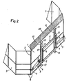
- jacks 5 On the side walls 3 act (see Fig 2) jacks 5 to ensure the rotation of these walls on the rear wall 1.
- These jacks are mounted, on the one hand on a yoke 6 integral with the wall 1, on the other hand on a yoke 7, integral with the side wall concerned, serving as a stop for the side walls in the open position of the device.
- the device is connected to the pusher vehicle by a system which is seen more particularly in FIG. 2.
- This system consists of a frame 8 comprising top and bottom coupling points 9 adapted as a function of the tool carriers of the pusher vehicle and which is mounted so as to be able to slide, against springs 10, on rods 11, made integral with the rear wall 1 and comprising, at each of their ends, a stop 12 limiting the stroke of the frame 8.
- the springs 10 are held between the upper stops of the rods and supports 13 provided on the frame 8.
- the device is provided with a bottom with a continuous surface, or not.
- this bottom consists of blades 14 mounted on rods, bars or the equivalent 15.
- the stems. 15 are actuated by jacks 16 fixed on the front face of the rear wall 1 and their ends pass through cam grooves 17, 18, which have parts 19 also integral with the rear wall 1.
- the upper groove 17 has a direction close to the vertical, the lower groove 18 from the horizontal, slightly inclined.
- the bottom of the device is placed in the two desired positions, observation being made that, as indicated above, the passage from the retracted position of the bottom to the horizontal position is only done once the object collection operation has been completed to avoid inadvertent pushing of the objects by the bottom brought prematurely to the horizontal deployed position.
- a protective grid 20 inclined towards the front of the device is mounted over the entire width of the wall, this grid serving as non-return when the objects, rubbish or the like, are trapped between the side walls in the closed position.
- These walls can take various forms. They can, as in the example treated, be folded substantially in the middle so as to intercept an angle of approximately 135 °, so that their ends are substantially perpendicular to the wall 1 in the open position and substantially parallel to this same wall in closed position to pre-compress and trap detritus.
- these walls can also be of generally curved shape, according to any desired curvature.
- the rear wall 1 can be of curved shape to present in its lower part an effective angle of attack and it is provided with cheeks at right angles on which are fixed the hinges of the side walls and practiced, in their lower part. , the cam grooves 17 and 18. On their upper part are fixed the jacks 16, these jacks then being external.
- the entire hydraulic system fitted to the device is double-acting, but pressure relief valves can be used on the return of the cylinders actuating the side walls and at the inlet of the cylinders actuating the retractable base, in order to allow successive movement of the side walls and the bottom with respect to the rear wall or vice versa depending on the desired result, namely to first close the side walls and deploy the bottom, then retract the bottom and open the side walls.
- control cylinders of the retractable bottom can be fixed on the rear face of the rear wall, which involves a modification of the coupling device to the pusher vehicle or a modification of the design of the rear wall. , as noted above.
Landscapes
- Life Sciences & Earth Sciences (AREA)
- Soil Sciences (AREA)
- Structural Engineering (AREA)
- Engineering & Computer Science (AREA)
- Architecture (AREA)
- Civil Engineering (AREA)
- Environmental Sciences (AREA)
- Loading Or Unloading Of Vehicles (AREA)
- Refuse-Collection Vehicles (AREA)
- Vehicle Cleaning, Maintenance, Repair, Refitting, And Outriggers (AREA)
- Refuse Collection And Transfer (AREA)
- Soil Working Implements (AREA)
- Vehicle Step Arrangements And Article Storage (AREA)
Claims (10)
Priority Applications (1)
| Application Number | Priority Date | Filing Date | Title |
|---|---|---|---|
| AT86400401T ATE36879T1 (de) | 1985-02-27 | 1986-02-25 | Fuer ein schiebendes fahrzeug anwendbare vorrichtung zum raeumen und laden von sich auf dem boden befindenden gegenstaenden, wie abfaelle. |
Applications Claiming Priority (2)
| Application Number | Priority Date | Filing Date | Title |
|---|---|---|---|
| FR8502868 | 1985-02-27 | ||
| FR8502868A FR2577957B1 (fr) | 1985-02-27 | 1985-02-27 | Dispositif pour deblaiement et chargement de detritus, adaptable sur vehicules pousseurs |
Publications (2)
| Publication Number | Publication Date |
|---|---|
| EP0193468A1 EP0193468A1 (de) | 1986-09-03 |
| EP0193468B1 true EP0193468B1 (de) | 1988-08-31 |
Family
ID=9316693
Family Applications (1)
| Application Number | Title | Priority Date | Filing Date |
|---|---|---|---|
| EP86400401A Expired EP0193468B1 (de) | 1985-02-27 | 1986-02-25 | Für ein schiebendes Fahrzeug anwendbare Vorrichtung zum Räumen und Laden von sich auf dem Boden befindenden Gegenständen, wie Abfälle |
Country Status (6)
| Country | Link |
|---|---|
| US (1) | US4779363A (de) |
| EP (1) | EP0193468B1 (de) |
| AT (1) | ATE36879T1 (de) |
| CA (1) | CA1267782A (de) |
| DE (1) | DE3660631D1 (de) |
| FR (1) | FR2577957B1 (de) |
Families Citing this family (38)
| Publication number | Priority date | Publication date | Assignee | Title |
|---|---|---|---|---|
| US4991662A (en) * | 1989-10-25 | 1991-02-12 | Caron Compactor Company | Land fill spreader blade assembly |
| US5127172A (en) * | 1991-08-28 | 1992-07-07 | Kenneth Lund | Guard rail cleanout device |
| US5241763A (en) * | 1991-12-17 | 1993-09-07 | Dynan David R | Plow attachment |
| WO1993022512A1 (en) * | 1992-05-01 | 1993-11-11 | Balderson Inc. | Blade assembly for a compacting vehicle |
| US5515624A (en) * | 1992-10-15 | 1996-05-14 | R. A. Beatty & Associates Pty Limited | Excavating hoe or bucket |
| US5599135A (en) * | 1995-06-08 | 1997-02-04 | Delaurenti; John | Asphalt spreader |
| US5638618A (en) * | 1996-06-07 | 1997-06-17 | Blizzard Corporation | Adjustable wing plow |
| US5899007A (en) * | 1996-06-07 | 1999-05-04 | Blizzard Corporation | Adjustable wing plow |
| US5848654A (en) * | 1996-07-01 | 1998-12-15 | Belcher, Jr.; Cliff | Laterally articulable blade for a bulldozer device or the like and method for use thereof |
| US5815957A (en) * | 1997-02-08 | 1998-10-06 | Mckeown; Ronald Wayne | Snowplow snow channeler |
| US6182385B1 (en) * | 1998-07-27 | 2001-02-06 | Ken's Enterprises, Inc. | Rock and material loading system |
| US6112438A (en) * | 1998-08-14 | 2000-09-05 | Pro-Tech Welding & Fabrication, Inc. | Snow plow |
| US5921326A (en) * | 1998-10-19 | 1999-07-13 | Ragule; Edward J. | Plow with folding auxiliary blade |
| US5988295A (en) * | 1999-02-16 | 1999-11-23 | Goulet; Luc | Adjustable grating attachment for grading soil |
| US6425196B1 (en) | 2000-08-08 | 2002-07-30 | Pro-Tech Welding And Fabrication, Inc. | Folding pusher |
| US6408549B1 (en) | 2000-10-12 | 2002-06-25 | Blizzard Corporation | Adjustable wing plow |
| US6442877B1 (en) | 2000-10-12 | 2002-09-03 | Blizzard Corporation | Plow with rear mounted, adjustable wing |
| US6412199B1 (en) | 2000-10-12 | 2002-07-02 | Blizzard Corporation | Adjustable wing plow with fixed pivot |
| US6763618B1 (en) * | 2003-03-11 | 2004-07-20 | Daniel Edward Moran | Combination rake and grubber implement |
| US7134227B2 (en) * | 2003-05-02 | 2006-11-14 | Douglas Dynamics, L.L.C. | Adjustable wing plow |
| US7360327B2 (en) * | 2004-02-12 | 2008-04-22 | Ralph L. Osgood, Inc. | Material moving pusher/bucket |
| US7481011B2 (en) * | 2004-03-30 | 2009-01-27 | Nth Inc. | Double wing scraper |
| US20070089327A1 (en) * | 2005-10-21 | 2007-04-26 | Watson Gary E | Plow with blade wing |
| US7681337B2 (en) * | 2005-10-21 | 2010-03-23 | Batesville Services, Inc. | Plow with blade wing |
| CA2566993C (en) | 2005-11-03 | 2012-10-02 | Pro-Tech Manufacturing And Distribution, Inc. | Reversible snow pusher and coupler |
| US20070163792A1 (en) * | 2006-01-17 | 2007-07-19 | Marlin Parrish | Land clearing rake |
| US20090188684A1 (en) * | 2006-01-17 | 2009-07-30 | Marlin Parrish | Land Clearing Rake |
| US7575067B1 (en) | 2007-05-22 | 2009-08-18 | Reyes Harvey A | Scraper system |
| US7762014B2 (en) * | 2008-04-29 | 2010-07-27 | Clark Equipment Company | Bucket debris guard |
| US8061063B2 (en) | 2008-06-17 | 2011-11-22 | Sno-Way International, Inc. | Plow wing blade |
| US7841109B2 (en) * | 2008-06-17 | 2010-11-30 | Sno-Way International, Inc. | Plow including independently moveable wings |
| US8065822B2 (en) * | 2008-06-17 | 2011-11-29 | Sno-Way International, Inc. | Height adjustment on plow a-frame |
| US8607482B2 (en) | 2011-02-28 | 2013-12-17 | Douglas Dynamics, L.L.C. | Plow with pivoting blade wing(s) |
| US9151006B2 (en) | 2012-02-09 | 2015-10-06 | Pro-Tech Manufacturing And Distribution, Inc. | Material pusher with control system |
| US8850724B2 (en) | 2013-02-15 | 2014-10-07 | Douglas Dynamics, L.L.C. | Plow with pivoting blade wing |
| KR101500176B1 (ko) * | 2013-10-28 | 2015-03-06 | 주식회사 포스코 | 이물질 수집유닛 및 이를 포함한 청소로봇 |
| US10132050B1 (en) * | 2018-04-27 | 2018-11-20 | Forest P. Mandan | Variable geometry bucket |
| US12012718B2 (en) * | 2019-10-16 | 2024-06-18 | Tilden Craig Harris | Ditch cutter and spoil removal apparatus |
Family Cites Families (8)
| Publication number | Priority date | Publication date | Assignee | Title |
|---|---|---|---|---|
| DE303384C (de) * | ||||
| US3166339A (en) * | 1961-11-17 | 1965-01-19 | Sam C Earley Corp | Folding lawn cart |
| US4089431A (en) * | 1976-09-15 | 1978-05-16 | Caterpillar Tractor Co. | Bucket with reduced dumping width |
| SU819271A1 (ru) * | 1979-05-15 | 1981-04-07 | Московский Автомобильно-Дорожныйинститут | Ковш экскаватора с двухщелевойСиСТЕМОй зАгРузКи |
| US4306362A (en) * | 1980-05-12 | 1981-12-22 | Valley Engineering, Inc. | Blade assembly |
| US4372617A (en) * | 1981-01-05 | 1983-02-08 | Frank J. Zamboni & Co. | Ice edger for ice resurfacing machine |
| US4619570A (en) * | 1982-03-30 | 1986-10-28 | Charles Siebenga | Bale loading-stacking apparatus |
| EP0097743A1 (de) * | 1982-06-29 | 1984-01-11 | Ogden Electronics Ltd. | Schneeräumgerät |
-
1985
- 1985-02-27 FR FR8502868A patent/FR2577957B1/fr not_active Expired
-
1986
- 1986-02-20 CA CA000502263A patent/CA1267782A/fr not_active Expired - Lifetime
- 1986-02-25 DE DE8686400401T patent/DE3660631D1/de not_active Expired
- 1986-02-25 EP EP86400401A patent/EP0193468B1/de not_active Expired
- 1986-02-25 US US06/832,699 patent/US4779363A/en not_active Expired - Fee Related
- 1986-02-25 AT AT86400401T patent/ATE36879T1/de active
Also Published As
| Publication number | Publication date |
|---|---|
| DE3660631D1 (en) | 1988-10-06 |
| CA1267782A (fr) | 1990-04-17 |
| FR2577957A1 (fr) | 1986-08-29 |
| US4779363A (en) | 1988-10-25 |
| ATE36879T1 (de) | 1988-09-15 |
| EP0193468A1 (de) | 1986-09-03 |
| FR2577957B1 (fr) | 1987-02-27 |
Similar Documents
| Publication | Publication Date | Title |
|---|---|---|
| EP0193468B1 (de) | Für ein schiebendes Fahrzeug anwendbare Vorrichtung zum Räumen und Laden von sich auf dem Boden befindenden Gegenständen, wie Abfälle | |
| US3072257A (en) | Combined gravel collecting and screening mechanism | |
| DE1901108A1 (de) | Einrichtung zum Abschneiden von Baumstaemmen und zum Einsammeln mehrerer abgeschnittener Staemme | |
| FR2549753A1 (fr) | Accessoire de manipulation et de cisaillage pour pelle retrochargeuse | |
| FR2659186A1 (fr) | Dispositif de travail agricole destine a etre monte a l'avant d'un tracteur. | |
| DE1484695B1 (de) | Schuerfkuebelfahrzeug | |
| EP0634981B1 (de) | Einziehbare einrichtung zum bedecken und öffnen eines zwei-oder dreidimensionalen platzes | |
| BE897326A (fr) | Dispositif pour la charge avec compression de solides dans un receptacle | |
| FR2641743A1 (fr) | Vehicule amenage pour etre equipe d'un outil interchangeable et outil destine a equiper un tel vehicule | |
| DE1756330A1 (de) | An einem Schlepper montierte Beladevorrichtung | |
| EP0440573B1 (de) | Stromabwärts arbeitender Rechenreiniger, stromaufwärts auswerfend einen klappbaren Kamm auweisend, der eingeklappt herunter geht und horizontal öffnet, den Rechen reinigend wieder aufsteigt und stromaufwärts eine bewegliche Abfuhrrinne | |
| EP2557235B1 (de) | Anbaugerät; Verfahren zur Aufnahme von auf einem Boden gelagerten Schüttgut | |
| FR2665429A1 (fr) | Grue a montage automatise, avec fleche repliable lateralement. | |
| FR2555660A1 (fr) | Dispositif pour la mise en place d'elements de soutenements marchants hydrauliques dans une exploitation souterraine, en particulier pour une taille fortement inclinee | |
| DE2509170A1 (de) | Einrichtung zur durchforstung von waeldern | |
| EP0268577B2 (de) | Ladekippschaufel | |
| FR2687533A1 (fr) | Dispositif de preparation de sol pour en retirer des objets. | |
| FR2584351A1 (fr) | Engin de broyage-recuperation de produits forestiers a benne basculante et deposable | |
| DE2416693A1 (de) | Greiferanordnung fuer einen loeffelbagger | |
| FR2629809A1 (fr) | Appareil de manutention de recipients tels que par exemple des bacs | |
| DE1918139A1 (de) | Schwenkpartie fuer Trichterboden in Kehrmaschinen | |
| DE1901108C (de) | Einrichtung zum Abschneiden und Ein sammeln mehrerer Stamme bzw Baume | |
| FR2676691A1 (fr) | Engin automoteur pour la realisation de travaux de manutention. | |
| SU419468A1 (ru) | Коник машины для бесчокерной трелевкидеревьев | |
| DE3011206A1 (de) | An ein kraftfahzeug anbaubare rueckevorrichtung |
Legal Events
| Date | Code | Title | Description |
|---|---|---|---|
| PUAI | Public reference made under article 153(3) epc to a published international application that has entered the european phase |
Free format text: ORIGINAL CODE: 0009012 |
|
| AK | Designated contracting states |
Kind code of ref document: A1 Designated state(s): AT BE CH DE FR GB IT LI LU NL SE |
|
| 17P | Request for examination filed |
Effective date: 19870113 |
|
| 17Q | First examination report despatched |
Effective date: 19871102 |
|
| GRAA | (expected) grant |
Free format text: ORIGINAL CODE: 0009210 |
|
| AK | Designated contracting states |
Kind code of ref document: B1 Designated state(s): AT BE CH DE FR GB IT LI LU NL SE |
|
| PG25 | Lapsed in a contracting state [announced via postgrant information from national office to epo] |
Ref country code: AT Effective date: 19880831 |
|
| REF | Corresponds to: |
Ref document number: 36879 Country of ref document: AT Date of ref document: 19880915 Kind code of ref document: T |
|
| REF | Corresponds to: |
Ref document number: 3660631 Country of ref document: DE Date of ref document: 19881006 |
|
| ITF | It: translation for a ep patent filed | ||
| GBT | Gb: translation of ep patent filed (gb section 77(6)(a)/1977) | ||
| PG25 | Lapsed in a contracting state [announced via postgrant information from national office to epo] |
Ref country code: LU Free format text: LAPSE BECAUSE OF NON-PAYMENT OF DUE FEES Effective date: 19890228 |
|
| PLBE | No opposition filed within time limit |
Free format text: ORIGINAL CODE: 0009261 |
|
| STAA | Information on the status of an ep patent application or granted ep patent |
Free format text: STATUS: NO OPPOSITION FILED WITHIN TIME LIMIT |
|
| 26N | No opposition filed | ||
| PG25 | Lapsed in a contracting state [announced via postgrant information from national office to epo] |
Ref country code: FR Free format text: LAPSE BECAUSE OF NON-PAYMENT OF DUE FEES Effective date: 19891027 |
|
| REG | Reference to a national code |
Ref country code: FR Ref legal event code: ST |
|
| ITTA | It: last paid annual fee | ||
| EAL | Se: european patent in force in sweden |
Ref document number: 86400401.5 |
|
| PGFP | Annual fee paid to national office [announced via postgrant information from national office to epo] |
Ref country code: GB Payment date: 19960226 Year of fee payment: 11 |
|
| PGFP | Annual fee paid to national office [announced via postgrant information from national office to epo] |
Ref country code: NL Payment date: 19960229 Year of fee payment: 11 |
|
| PGFP | Annual fee paid to national office [announced via postgrant information from national office to epo] |
Ref country code: BE Payment date: 19960313 Year of fee payment: 11 |
|
| PGFP | Annual fee paid to national office [announced via postgrant information from national office to epo] |
Ref country code: CH Payment date: 19960320 Year of fee payment: 11 |
|
| PGFP | Annual fee paid to national office [announced via postgrant information from national office to epo] |
Ref country code: SE Payment date: 19960321 Year of fee payment: 11 |
|
| PGFP | Annual fee paid to national office [announced via postgrant information from national office to epo] |
Ref country code: DE Payment date: 19960330 Year of fee payment: 11 |
|
| PG25 | Lapsed in a contracting state [announced via postgrant information from national office to epo] |
Ref country code: GB Effective date: 19970225 |
|
| PG25 | Lapsed in a contracting state [announced via postgrant information from national office to epo] |
Ref country code: SE Effective date: 19970226 |
|
| PG25 | Lapsed in a contracting state [announced via postgrant information from national office to epo] |
Ref country code: LI Effective date: 19970228 Ref country code: CH Effective date: 19970228 Ref country code: BE Effective date: 19970228 |
|
| BERE | Be: lapsed |
Owner name: CHARRAIRE BERNARD Effective date: 19970228 Owner name: BOUTRAIS JACQUES Effective date: 19970228 |
|
| PG25 | Lapsed in a contracting state [announced via postgrant information from national office to epo] |
Ref country code: NL Effective date: 19970901 |
|
| GBPC | Gb: european patent ceased through non-payment of renewal fee |
Effective date: 19970225 |
|
| REG | Reference to a national code |
Ref country code: CH Ref legal event code: PL |
|
| PG25 | Lapsed in a contracting state [announced via postgrant information from national office to epo] |
Ref country code: DE Effective date: 19971101 |
|
| EUG | Se: european patent has lapsed |
Ref document number: 86400401.5 |
|
| NLV4 | Nl: lapsed or anulled due to non-payment of the annual fee |
Effective date: 19970901 |
|
| PG25 | Lapsed in a contracting state [announced via postgrant information from national office to epo] |
Ref country code: IT Free format text: LAPSE BECAUSE OF NON-PAYMENT OF DUE FEES Effective date: 20050225 |