EP0193468B1 - Device adaptable to a pushing vehicle for cleaning and loading objects, such as refuse, lying on the ground - Google Patents
Device adaptable to a pushing vehicle for cleaning and loading objects, such as refuse, lying on the ground Download PDFInfo
- Publication number
- EP0193468B1 EP0193468B1 EP86400401A EP86400401A EP0193468B1 EP 0193468 B1 EP0193468 B1 EP 0193468B1 EP 86400401 A EP86400401 A EP 86400401A EP 86400401 A EP86400401 A EP 86400401A EP 0193468 B1 EP0193468 B1 EP 0193468B1
- Authority
- EP
- European Patent Office
- Prior art keywords
- die
- der
- und
- daß
- sind
- Prior art date
- Legal status (The legal status is an assumption and is not a legal conclusion. Google has not performed a legal analysis and makes no representation as to the accuracy of the status listed.)
- Expired
Links
Images


Classifications
-
- E—FIXED CONSTRUCTIONS
- E01—CONSTRUCTION OF ROADS, RAILWAYS, OR BRIDGES
- E01H—STREET CLEANING; CLEANING OF PERMANENT WAYS; CLEANING BEACHES; DISPERSING OR PREVENTING FOG IN GENERAL CLEANING STREET OR RAILWAY FURNITURE OR TUNNEL WALLS
- E01H1/00—Removing undesirable matter from roads or like surfaces, with or without moistening of the surface
- E01H1/10—Hydraulically loosening or dislodging undesirable matter; Raking or scraping apparatus ; Removing liquids or semi-liquids e.g., absorbing water, sliding-off mud
- E01H1/105—Raking, scraping or other mechanical loosening devices, e.g. for caked dirt ; Apparatus for mechanically moving dirt on road surfaces, e.g. wipers for evacuating mud
- E01H1/106—Raking, scraping or other mechanical loosening devices, e.g. for caked dirt ; Apparatus for mechanically moving dirt on road surfaces, e.g. wipers for evacuating mud in which the loosened or dislodged dirt is picked up, e.g. shoveling carts
-
- A—HUMAN NECESSITIES
- A01—AGRICULTURE; FORESTRY; ANIMAL HUSBANDRY; HUNTING; TRAPPING; FISHING
- A01C—PLANTING; SOWING; FERTILISING
- A01C3/00—Treating manure; Manuring
- A01C3/04—Manure loaders
Definitions
- the present invention relates to a device adaptable on a pusher vehicle, intended to collect, with a view to their collection and possibly their loading, objects lying on the ground.
- This device is more particularly, but of course not exclusively, intended to be used for cleaning litter from roads, markets, drop-off depots, etc. This list of uses is obviously not exhaustive.
- the device according to the invention enables this operation to be carried out under optimal conditions of speed, ease and efficiency.
- This device suitable for a pusher vehicle and comprising, as is known from document US-A-4 306 362, a substantially vertical fixed rear wall on which the side walls are articulated is characterized in that the rear wall is provided at its lower part, of means, erasable, forming a lifting bottom for the collection of litter, their transport and possibly their elevation.
- the rear wall of the device is connected to the pusher vehicle by a system comprising damping means ensuring on the one hand the suspension of the device during its movements, on the other hand the constant application on the ground of the base of the rear wall in position of work, whatever the unevenness of the ground.
- the damping system consists of a support frame capable of being coupled to the pusher vehicle and mounted so as to be able to slide against springs on rods or bars integral with the rear wall, between a high stop and a low stop. that these rods comprise, these stops limiting the movement of the support frame and the springs being compressed between the upper stops of the rods or bars and the corresponding upper part of the support frame.
- the retractable base has a continuous or non-continuous surface, such as a frame with blades, subjected to the action of means such as jacks and capable of occupying two positions, one close to the vertical, while the objects are being pushed. , the other, horizontal, to support objects for their transport and possibly their elevation.
- the chassis blades are mounted on rods or bars, parallel, subjected to the action of means such as jacks, these rods or bars being themselves mounted on parts provided with means allowing the chassis to pass from the vertical position, erased, at the horizontal position of the latter.
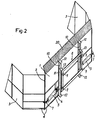
- the device comprises a substantially vertical rear wall 1, adaptable to a pusher vehicle and on which are hinged, by hinges 2, side walls 3. Under these side walls, as well as under the rear wall 1 , are provided flaps 4, allowing the scraping of the soil of the device during its push.
- flaps are mounted on the walls they equip so as to move in the vertical plane to allow them to match the unevenness of the ground.
- This assembly can for example be achieved by means of a rod secured to the flap and fixed to the wall concerned, surrounded by a compressed spring between a stop and the flap itself and urging the latter towards the ground.
- jacks 5 On the side walls 3 act (see Fig 2) jacks 5 to ensure the rotation of these walls on the rear wall 1.
- These jacks are mounted, on the one hand on a yoke 6 integral with the wall 1, on the other hand on a yoke 7, integral with the side wall concerned, serving as a stop for the side walls in the open position of the device.
- the device is connected to the pusher vehicle by a system which is seen more particularly in FIG. 2.
- This system consists of a frame 8 comprising top and bottom coupling points 9 adapted as a function of the tool carriers of the pusher vehicle and which is mounted so as to be able to slide, against springs 10, on rods 11, made integral with the rear wall 1 and comprising, at each of their ends, a stop 12 limiting the stroke of the frame 8.
- the springs 10 are held between the upper stops of the rods and supports 13 provided on the frame 8.
- the device is provided with a bottom with a continuous surface, or not.
- this bottom consists of blades 14 mounted on rods, bars or the equivalent 15.
- the stems. 15 are actuated by jacks 16 fixed on the front face of the rear wall 1 and their ends pass through cam grooves 17, 18, which have parts 19 also integral with the rear wall 1.
- the upper groove 17 has a direction close to the vertical, the lower groove 18 from the horizontal, slightly inclined.
- the bottom of the device is placed in the two desired positions, observation being made that, as indicated above, the passage from the retracted position of the bottom to the horizontal position is only done once the object collection operation has been completed to avoid inadvertent pushing of the objects by the bottom brought prematurely to the horizontal deployed position.
- a protective grid 20 inclined towards the front of the device is mounted over the entire width of the wall, this grid serving as non-return when the objects, rubbish or the like, are trapped between the side walls in the closed position.
- These walls can take various forms. They can, as in the example treated, be folded substantially in the middle so as to intercept an angle of approximately 135 °, so that their ends are substantially perpendicular to the wall 1 in the open position and substantially parallel to this same wall in closed position to pre-compress and trap detritus.
- these walls can also be of generally curved shape, according to any desired curvature.
- the rear wall 1 can be of curved shape to present in its lower part an effective angle of attack and it is provided with cheeks at right angles on which are fixed the hinges of the side walls and practiced, in their lower part. , the cam grooves 17 and 18. On their upper part are fixed the jacks 16, these jacks then being external.
- the entire hydraulic system fitted to the device is double-acting, but pressure relief valves can be used on the return of the cylinders actuating the side walls and at the inlet of the cylinders actuating the retractable base, in order to allow successive movement of the side walls and the bottom with respect to the rear wall or vice versa depending on the desired result, namely to first close the side walls and deploy the bottom, then retract the bottom and open the side walls.
- control cylinders of the retractable bottom can be fixed on the rear face of the rear wall, which involves a modification of the coupling device to the pusher vehicle or a modification of the design of the rear wall. , as noted above.
Abstract
Description
La présente invention concerne un dispositif adaptable sur véhicule pousseur, destiné à collecter en vue de leur ramassage et éventuellement de leur chargement, des objets se trouvant sur le sol. Ce dispositif est plus particulièrement, mais bien entendu non exclusivement, appelé à être utilisé pour le nettoyage des détritus de voierie, de marchés, de dépôt-relais, etc... Cette liste d'utilisations n'étant évidemment pas limitative.The present invention relates to a device adaptable on a pusher vehicle, intended to collect, with a view to their collection and possibly their loading, objects lying on the ground. This device is more particularly, but of course not exclusively, intended to be used for cleaning litter from roads, markets, drop-off depots, etc. This list of uses is obviously not exhaustive.
Actuellement ce ramassage est effectué manuellement, à l'aide d'outils rudimentaires et au prix d'un travail long, pénible et coûteux.Currently this collection is done manually, using rudimentary tools and at the cost of long, tedious and expensive work.
Le dispositif suivant l'invention permet d'effectuer cette opération dans des conditions optimales de rapidicé, de facilité et d'efficacité.The device according to the invention enables this operation to be carried out under optimal conditions of speed, ease and efficiency.
Ce dispositif, adapte sur un véhicule pousseur et comportant, comme il est connu du document US-A-4 306 362, une paroi arrière fixe sensiblement verticale sur laquelle sont articulées des parois latérales est caractérisé en ce que la paroi arrière est munie à sa partie inférieure, de moyens, effaçables, formant fond relevable pour la collecte des détritus, leur transport et éventuellement leur élévation.This device, suitable for a pusher vehicle and comprising, as is known from document US-A-4 306 362, a substantially vertical fixed rear wall on which the side walls are articulated is characterized in that the rear wall is provided at its lower part, of means, erasable, forming a lifting bottom for the collection of litter, their transport and possibly their elevation.
La paroi arrière du dispositif est reliée au véhicule pousseur par un système comportant des moyens amortisseurs assurant d'une part la suspension du dispositif pendant ses déplacements, d'autre part l'application constante sur le sol de la base de la paroi arrière en position de travail, quelles que soient les dénivellations du sol.The rear wall of the device is connected to the pusher vehicle by a system comprising damping means ensuring on the one hand the suspension of the device during its movements, on the other hand the constant application on the ground of the base of the rear wall in position of work, whatever the unevenness of the ground.
Le système amortisseur est constitué par un cadre-support susceptible d'être attelé au véhicule pousseur et monté de façon à pouvoir coulisser à l'encontre de ressorts sur des tiges ou barres solidaires de la paroi arrière, entre une butée haute et une butée basse que comportent ces tiges, ces butées limitant le déplacement du cadre-support et les ressorts étant comprimés entre les butées hautes des tiges ou barres et la partie haute correspondante du cadre-support.The damping system consists of a support frame capable of being coupled to the pusher vehicle and mounted so as to be able to slide against springs on rods or bars integral with the rear wall, between a high stop and a low stop. that these rods comprise, these stops limiting the movement of the support frame and the springs being compressed between the upper stops of the rods or bars and the corresponding upper part of the support frame.
Sur la paroi arrière est monté un fond, rétracté pendant la phase de poussage des objets tels que détritus et déployé une fois ces objets enserrés entre la paroi arrière et les parois latérales du dispositif, en vue de leur ramassage.On the rear wall is mounted a bottom, retracted during the pushing phase of objects such as litter and deployed once these objects are sandwiched between the rear wall and the side walls of the device, for their collection.
Le fond rétractable présente une surface continue ou non, telle que châssis à lames, soumise à l'action de moyens tels que vérins et susceptible d'occuper deux positions l'une voisine de la verticale, pendant que s'effectue le poussage des objets, l'autre, horizontale, pour supporter les objets en vue de leur transport et éventuellement de leur élévation.The retractable base has a continuous or non-continuous surface, such as a frame with blades, subjected to the action of means such as jacks and capable of occupying two positions, one close to the vertical, while the objects are being pushed. , the other, horizontal, to support objects for their transport and possibly their elevation.
Les lames du châssis sont montées sur des tiges ou barres, parallèles, soumises à l'action de moyens tels que vérins, ces tiges ou barres étant elles-mêmes montées sur des pièces munies de moyens permettant le passage du châssis de la position verticale, effacée, à la position horizontale de ce dernier.The chassis blades are mounted on rods or bars, parallel, subjected to the action of means such as jacks, these rods or bars being themselves mounted on parts provided with means allowing the chassis to pass from the vertical position, erased, at the horizontal position of the latter.
Les divers caractéristiques et avantages de l'invention ressortiront de la description qui va suivre de quelques formes possibles de réalisation. Il est bien précisé qu'il s'agit uniquement d'exemples non limitatifs et que toutes autres dispositions pourraient être adoptées sans sortie du cadre de l'invention.The various characteristics and advantages of the invention will emerge from the description which follows of some possible embodiments. It is clearly specified that these are only non-limiting examples and that any other provisions could be adopted without departing from the scope of the invention.
Au cours de cette description on se réfère aux dessins ci-joints sur lesquels:
- la Fig.1 est une vue en perspective de 3/4 avant d'undispositif suivant l'invention,
- la Fig. 2 est une vue, analogue à la Fig. 1 mais de 3/4 arrière, d'un tel dispositif,
- la Fig. 3 est une vue de dessus du dispositif en position ouverte des parois latérales, le fond rétracté,
- la Fig. 4 est une vue de dessus du dispositif en position fermée des parois latérales et le fond déployé,
- la Fig. 5 est une vue en coupe suivant A-A' de la Fig. 3, et
- la Fig. 6 est une vue en coupe suivant B-B' de la Fig. 4.
- Fig. 1 is a 3/4 front perspective view of a device according to the invention,
- Fig. 2 is a view, similar to FIG. 1 but 3/4 rear, of such a device,
- Fig. 3 is a top view of the device in the open position of the side walls, the bottom retracted,
- Fig. 4 is a top view of the device in the closed position of the side walls and the deployed bottom,
- Fig. 5 is a sectional view along AA 'of FIG. 3, and
- Fig. 6 is a sectional view along BB 'of FIG. 4.
Dans l'exemple traité, le dispositif comporte une paroi arrière sensiblement verticale 1, adaptable sur un véhicule pousseur et sur laquelle sont articulées, par des charnières 2, des parois latérales 3. Sous ces parois latérales, aussi bien que sous la paroi arrière 1, sont prévues des bavettes 4, permettant le raclage du sol du dispositif lors de sa poussée. Avantageusement, ces bavettes sont montées sur les parois qu'elles équipent de façon à se déplacer dans le plan vertical pour leur permettre d'épouser les inégalités du sol. Ce montage peut par exemple être réalisé au moyen d'une tige solidaire de la bavette et fixée sur la paroi intéressée, entourée d'un ressort comprimé entre une butée et la bavette elle-même et sollicitant cette dernière vers le sol. Sur les parois latérales 3 agissent (voir Fig 2) des vérins 5 pour assurer la rotation de ces parois sur la paroi arrière 1. Ces vérins sont montés, d'une part sur une chape 6 solidaire de la paroi 1, d'autre part sur une chape 7, solidaire de la paroi latérale concernée, servant de butée aux parois latérales en position ouverte du dispositif.In the example treated, the device comprises a substantially vertical
Le dispositif est relié au véhicule pousseur par un système que l'on voit plus particulièrement sur la Fig. 2. Ce système consiste en un cadre 8 comportant des points 9 d'attelage haut et bas adaptés en fonction des porte-outils du véhicule pousseur et qui est monté, de façon à pouvoir coulisser, à l'encontre de ressorts 10, sur des tiges 11, rendues solidaires de la paroi arrière 1 et comportant, à chacune de leurs extrémités, une butée 12 limitant la course du cadre 8. Les ressorts 10 sont maintenus entre les butées supérieures des tiges et des appuis 13 prévus sur le cadre 8.The device is connected to the pusher vehicle by a system which is seen more particularly in FIG. 2. This system consists of a
Ces dispositions, suivant l'invention, assurent d'une part la suspension élastique du dispositif pendant ses déplacements, d'autre part l'application constante sur le sol de la base de la paroi arrière en position de travail, quelles qu'en soient les dénivellations.These arrangements, according to the invention, ensure on the one hand the elastic suspension of the device during its movements, on the other hand the constant application on the ground of the base of the rear wall in working position, whatever the differences in level.
Le dispositif est muni, suivant l'invention, d'un fond à surface continue, ou non. Dans la forme de réalisation représentée aux Fig. 3 à 6, ce fond est constitué par des lames 14 montées sur des tiges, barres ou l'équivalent 15.According to the invention, the device is provided with a bottom with a continuous surface, or not. In the embodiment shown in Figs. 3 to 6, this bottom consists of
Pour que le fond puisse occuper deux positions une position rétractée, voisine de la verticale, comme le montre la Fig. 3, aussi bien pendant les déplacements du dispositif que pendant l'opération de ramassage des objets, pour éviter de les pousser hors de sa zone d'action, et une position déployée voisine de l'horizontale, une fois effectué le ramassage des objets, les tiges. 15 sont actionnées par des vérins 16 fixés sur la face antérieure de la paroi arrière 1 et leurs extrémités passent dans des rainures de cames 17,18, que présentent des pièces 19 solidaires également de la paroi arrière 1.So that the bottom can occupy two positions in a retracted position, close to the vertical, as shown in Fig. 3, both during movement of the device and during the operation of picking up objects, to avoid pushing them out of its area of action, and a deployed position close to the horizontal, once the objects have been picked up, the stems. 15 are actuated by
La rainure haute 17 est de direction voisine de la verticale, la rainure basse 18 de l'horizontale, légèrement inclinée.The
Ainsi est réalisée, suivant l'invention, la mise dans les deux positions voulues, du fond du dispositif, observation étant faite que, comme signalé plus haut, le passage de la position rétractée du fond à la position horizontale ne se fait qu'une fois terminée l'opération de collecte des objets pour éviter une poussée intempestive des objets par le fond amené prématurément à la position horizontale déployée.Thus, according to the invention, the bottom of the device is placed in the two desired positions, observation being made that, as indicated above, the passage from the retracted position of the bottom to the horizontal position is only done once the object collection operation has been completed to avoid inadvertent pushing of the objects by the bottom brought prematurely to the horizontal deployed position.
Une grille de protection 20 inclinée vers l'avant du dispositif est montée sur toute la largeur de la paroi, cette grille servant d'anti-retour lorsque les objets, détritus ou autres, sont emprisonnés entre les parois latérales en position fermée.A
Ces parois peuvent affecter diverses formes. Elles peuvent, comme dans l'exemple traité, être pliées sensiblement en leur milieu de façon à intercepter un angle d'environ 135°, afin que leurs extrémités soient sensiblement perpendiculaires à la paroi 1 en position ouverte et sensiblement parallèles à cette même paroi en position fermée afin de précomprimer les détritus et de les emprisonner.These walls can take various forms. They can, as in the example treated, be folded substantially in the middle so as to intercept an angle of approximately 135 °, so that their ends are substantially perpendicular to the
Cependant ces parois peuvent également être de forme générale courbe, suivant toute courbure voulue.However, these walls can also be of generally curved shape, according to any desired curvature.
Quant à la paroi arrière 1, elle peut être de forme courbe pour présenter dans sa partie basse un angle d'attaque efficace et elle est munie de joues à angle droit sur lesquelles sont fixées les charnières des parois latérales et pratiquées, dans leur partie inférieure, les rainures de came 17 et 18. Sur leur partie supérieure sont fixés les vérins 16, ces vérins étant alors externes.As for the
L'ensemble du système hydraulique équipant le dispositif est à double effet mais l'on peut utiliser des limiteurs de pression au retour des vérins actionnant les parois latérales et à l'entrée des vérins actionnant le fond rétractable, afin de permettre un mouvement successif des parois latérales et du fond par rapport à la paroi arrière ou inversement suivant le résultat recherché, savoir dans un premier temps fermer les parois latérales et déployer le fond, dans un deuxième temps rétracter le fond et ouvrir les parois latérales.The entire hydraulic system fitted to the device is double-acting, but pressure relief valves can be used on the return of the cylinders actuating the side walls and at the inlet of the cylinders actuating the retractable base, in order to allow successive movement of the side walls and the bottom with respect to the rear wall or vice versa depending on the desired result, namely to first close the side walls and deploy the bottom, then retract the bottom and open the side walls.
D'une façon générale l'invention peut donner lieu à de nombreuses variantes sans que, ce faisant, on sorte de son cadre.In general, the invention can give rise to numerous variants without, in doing so, departing from its scope.
C'est ainsi, par exemple, que les vérins de commande du fond rétractable peuvent être fixés sur la face postérieure de la paroi arrière, ce qui entraîne une modification du dispositif d'accouplement au véhicule pousseur ou une modification du dessin de la paroi arrière, ainsi qu'on l'a fait remarquer plus haut.Thus, for example, the control cylinders of the retractable bottom can be fixed on the rear face of the rear wall, which involves a modification of the coupling device to the pusher vehicle or a modification of the design of the rear wall. , as noted above.
Quant aux limiteurs de pression auxquels on a fait allusion plus haut, ils sont inutiles si les mouvements du fond et ceux des parois latérales sont commandés de façon indépendante par asservissement hydraulique au moyen d'une fonction double effet s'appliquant à chacun de ces organes.As for the pressure limiters to which we alluded above, they are useless if the movements of the bottom and those of the side walls are controlled independently by hydraulic servo control by means of a double effect function applying to each of these members .
Claims (10)
Priority Applications (1)
| Application Number | Priority Date | Filing Date | Title |
|---|---|---|---|
| AT86400401T ATE36879T1 (en) | 1985-02-27 | 1986-02-25 | DEVICE APPLICABLE TO A PUSHING VEHICLE FOR CLEARING AND LOADING OBJECTS ON THE GROUND, SUCH AS WASTE. |
Applications Claiming Priority (2)
| Application Number | Priority Date | Filing Date | Title |
|---|---|---|---|
| FR8502868A FR2577957B1 (en) | 1985-02-27 | 1985-02-27 | DEVICE FOR CLEARING AND LOADING DETRITUS, ADAPTABLE ON PUSHING VEHICLES |
| FR8502868 | 1985-02-27 |
Publications (2)
| Publication Number | Publication Date |
|---|---|
| EP0193468A1 EP0193468A1 (en) | 1986-09-03 |
| EP0193468B1 true EP0193468B1 (en) | 1988-08-31 |
Family
ID=9316693
Family Applications (1)
| Application Number | Title | Priority Date | Filing Date |
|---|---|---|---|
| EP86400401A Expired EP0193468B1 (en) | 1985-02-27 | 1986-02-25 | Device adaptable to a pushing vehicle for cleaning and loading objects, such as refuse, lying on the ground |
Country Status (6)
| Country | Link |
|---|---|
| US (1) | US4779363A (en) |
| EP (1) | EP0193468B1 (en) |
| AT (1) | ATE36879T1 (en) |
| CA (1) | CA1267782A (en) |
| DE (1) | DE3660631D1 (en) |
| FR (1) | FR2577957B1 (en) |
Families Citing this family (38)
| Publication number | Priority date | Publication date | Assignee | Title |
|---|---|---|---|---|
| US4991662A (en) * | 1989-10-25 | 1991-02-12 | Caron Compactor Company | Land fill spreader blade assembly |
| US5127172A (en) * | 1991-08-28 | 1992-07-07 | Kenneth Lund | Guard rail cleanout device |
| US5241763A (en) * | 1991-12-17 | 1993-09-07 | Dynan David R | Plow attachment |
| EP0600047A1 (en) * | 1992-05-01 | 1994-06-08 | Balderson Inc. | Blade assembly for a compacting vehicle |
| US5515624A (en) * | 1992-10-15 | 1996-05-14 | R. A. Beatty & Associates Pty Limited | Excavating hoe or bucket |
| US5599135A (en) * | 1995-06-08 | 1997-02-04 | Delaurenti; John | Asphalt spreader |
| US5899007A (en) * | 1996-06-07 | 1999-05-04 | Blizzard Corporation | Adjustable wing plow |
| US5638618A (en) * | 1996-06-07 | 1997-06-17 | Blizzard Corporation | Adjustable wing plow |
| US5848654A (en) * | 1996-07-01 | 1998-12-15 | Belcher, Jr.; Cliff | Laterally articulable blade for a bulldozer device or the like and method for use thereof |
| US5815957A (en) * | 1997-02-08 | 1998-10-06 | Mckeown; Ronald Wayne | Snowplow snow channeler |
| US6182385B1 (en) * | 1998-07-27 | 2001-02-06 | Ken's Enterprises, Inc. | Rock and material loading system |
| US6112438A (en) * | 1998-08-14 | 2000-09-05 | Pro-Tech Welding & Fabrication, Inc. | Snow plow |
| US5921326A (en) * | 1998-10-19 | 1999-07-13 | Ragule; Edward J. | Plow with folding auxiliary blade |
| US5988295A (en) * | 1999-02-16 | 1999-11-23 | Goulet; Luc | Adjustable grating attachment for grading soil |
| US6425196B1 (en) | 2000-08-08 | 2002-07-30 | Pro-Tech Welding And Fabrication, Inc. | Folding pusher |
| US6408549B1 (en) | 2000-10-12 | 2002-06-25 | Blizzard Corporation | Adjustable wing plow |
| US6412199B1 (en) | 2000-10-12 | 2002-07-02 | Blizzard Corporation | Adjustable wing plow with fixed pivot |
| US6442877B1 (en) | 2000-10-12 | 2002-09-03 | Blizzard Corporation | Plow with rear mounted, adjustable wing |
| US6763618B1 (en) * | 2003-03-11 | 2004-07-20 | Daniel Edward Moran | Combination rake and grubber implement |
| US7134227B2 (en) * | 2003-05-02 | 2006-11-14 | Douglas Dynamics, L.L.C. | Adjustable wing plow |
| US7360327B2 (en) * | 2004-02-12 | 2008-04-22 | Ralph L. Osgood, Inc. | Material moving pusher/bucket |
| US7481011B2 (en) * | 2004-03-30 | 2009-01-27 | Nth Inc. | Double wing scraper |
| US7681337B2 (en) * | 2005-10-21 | 2010-03-23 | Batesville Services, Inc. | Plow with blade wing |
| US20070089327A1 (en) * | 2005-10-21 | 2007-04-26 | Watson Gary E | Plow with blade wing |
| US8621769B2 (en) | 2005-11-03 | 2014-01-07 | Pro-Tech Manufacturing And Distribution, Inc. | Snow pusher for ice and snow removal |
| US20090188684A1 (en) * | 2006-01-17 | 2009-07-30 | Marlin Parrish | Land Clearing Rake |
| US20070163792A1 (en) * | 2006-01-17 | 2007-07-19 | Marlin Parrish | Land clearing rake |
| US7575067B1 (en) | 2007-05-22 | 2009-08-18 | Reyes Harvey A | Scraper system |
| US7762014B2 (en) * | 2008-04-29 | 2010-07-27 | Clark Equipment Company | Bucket debris guard |
| US7841109B2 (en) * | 2008-06-17 | 2010-11-30 | Sno-Way International, Inc. | Plow including independently moveable wings |
| US8061063B2 (en) | 2008-06-17 | 2011-11-22 | Sno-Way International, Inc. | Plow wing blade |
| US7934328B2 (en) * | 2008-06-17 | 2011-05-03 | Sno-Way International, Inc. | V-plow cutting edge interface |
| US8607482B2 (en) | 2011-02-28 | 2013-12-17 | Douglas Dynamics, L.L.C. | Plow with pivoting blade wing(s) |
| US9151006B2 (en) | 2012-02-09 | 2015-10-06 | Pro-Tech Manufacturing And Distribution, Inc. | Material pusher with control system |
| US8850724B2 (en) | 2013-02-15 | 2014-10-07 | Douglas Dynamics, L.L.C. | Plow with pivoting blade wing |
| KR101500176B1 (en) * | 2013-10-28 | 2015-03-06 | 주식회사 포스코 | Sludge collecting unit and cleaning robot having thereof |
| US10132050B1 (en) * | 2018-04-27 | 2018-11-20 | Forest P. Mandan | Variable geometry bucket |
| US20210115646A1 (en) * | 2019-10-16 | 2021-04-22 | Tilden Craig Harris | Ditch cutter and spoil removal appratus |
Family Cites Families (8)
| Publication number | Priority date | Publication date | Assignee | Title |
|---|---|---|---|---|
| DE303384C (en) * | ||||
| US3166339A (en) * | 1961-11-17 | 1965-01-19 | Sam C Earley Corp | Folding lawn cart |
| US4089431A (en) * | 1976-09-15 | 1978-05-16 | Caterpillar Tractor Co. | Bucket with reduced dumping width |
| SU819271A1 (en) * | 1979-05-15 | 1981-04-07 | Московский Автомобильно-Дорожныйинститут | Excavator bucket with twin-slit loading system |
| US4306362A (en) * | 1980-05-12 | 1981-12-22 | Valley Engineering, Inc. | Blade assembly |
| US4372617A (en) * | 1981-01-05 | 1983-02-08 | Frank J. Zamboni & Co. | Ice edger for ice resurfacing machine |
| US4619570A (en) * | 1982-03-30 | 1986-10-28 | Charles Siebenga | Bale loading-stacking apparatus |
| EP0097743A1 (en) * | 1982-06-29 | 1984-01-11 | Ogden Electronics Ltd. | Improved snow clearing device |
-
1985
- 1985-02-27 FR FR8502868A patent/FR2577957B1/en not_active Expired
-
1986
- 1986-02-20 CA CA000502263A patent/CA1267782A/en not_active Expired - Lifetime
- 1986-02-25 US US06/832,699 patent/US4779363A/en not_active Expired - Fee Related
- 1986-02-25 AT AT86400401T patent/ATE36879T1/en active
- 1986-02-25 EP EP86400401A patent/EP0193468B1/en not_active Expired
- 1986-02-25 DE DE8686400401T patent/DE3660631D1/en not_active Expired
Also Published As
| Publication number | Publication date |
|---|---|
| CA1267782A (en) | 1990-04-17 |
| FR2577957B1 (en) | 1987-02-27 |
| FR2577957A1 (en) | 1986-08-29 |
| ATE36879T1 (en) | 1988-09-15 |
| EP0193468A1 (en) | 1986-09-03 |
| DE3660631D1 (en) | 1988-10-06 |
| US4779363A (en) | 1988-10-25 |
Similar Documents
| Publication | Publication Date | Title |
|---|---|---|
| EP0193468B1 (en) | Device adaptable to a pushing vehicle for cleaning and loading objects, such as refuse, lying on the ground | |
| DE1901108A1 (en) | Device for cutting tree trunks and collecting several cut trunks | |
| FR2549753A1 (en) | HANDLING AND SHEARING ACCESSORY FOR BACKHOE SHOVEL | |
| FR2659186A1 (en) | AGRICULTURAL WORKING DEVICE FOR MOUNTING FRONT OF A TRACTOR. | |
| EP0634981B1 (en) | Retractable device for raising and lowering a cover over a two or three dimensional space | |
| DE1756330A1 (en) | Loading device mounted on a tractor | |
| EP2557235B1 (en) | Attachment; method for receiving bulk material stored on a floor | |
| DE20307880U1 (en) | Lifting device for loads in luggage space of vehicle, has energy accumulator between base plate and lockable load support plate | |
| FR2679544A1 (en) | Autonomous (self-contained) equipment making it possible to extract and move elements which are set into the ground, such as manhole covers, gratings | |
| FR2665429A1 (en) | AUTOMATED MOUNT CRANE, WITH LATERAL FOLDABLE BOOM. | |
| FR2555660A1 (en) | Steep mine front striding hydraulic supports placing system | |
| EP0268577B2 (en) | Tipping loading shovel | |
| FR2687533A1 (en) | Device for preparing the land for removing objects therefrom | |
| FR2584351A1 (en) | Vehicle for grinding/recovering forestry products having a skip which can be tipped and laid down | |
| DE2416693A1 (en) | Grab arrangement for shovel dredgers - claws can compress rubble and lower claw removes small rubble from ground | |
| DE1484695C (en) | Schurfkubel vehicle | |
| FR2629809A1 (en) | APPARATUS FOR HANDLING CONTAINERS SUCH AS FOR EXAMPLE BAGS | |
| DE1918139A1 (en) | Swivel section for hopper bottom in sweepers | |
| DE1901108C (en) | Device for cutting and collecting several trunks or trees | |
| FR2676691A1 (en) | Self-propelled vehicle for carrying out handling work | |
| DE202010009745U1 (en) | Device for emptying gullet buckets | |
| SU419468A1 (en) | KONIK MACHINES FOR UNBLOCK-DOOR TRAILS | |
| DE3011206A1 (en) | Front end attachment for vehicle - has swing arm connected with holder via two spaced levers | |
| DE1935652C3 (en) | Tractor equipped with a winch | |
| FR2748629A1 (en) | FOLDABLE SOIL OR PLANT TREATMENT APPARATUS |
Legal Events
| Date | Code | Title | Description |
|---|---|---|---|
| PUAI | Public reference made under article 153(3) epc to a published international application that has entered the european phase |
Free format text: ORIGINAL CODE: 0009012 |
|
| AK | Designated contracting states |
Kind code of ref document: A1 Designated state(s): AT BE CH DE FR GB IT LI LU NL SE |
|
| 17P | Request for examination filed |
Effective date: 19870113 |
|
| 17Q | First examination report despatched |
Effective date: 19871102 |
|
| GRAA | (expected) grant |
Free format text: ORIGINAL CODE: 0009210 |
|
| AK | Designated contracting states |
Kind code of ref document: B1 Designated state(s): AT BE CH DE FR GB IT LI LU NL SE |
|
| PG25 | Lapsed in a contracting state [announced via postgrant information from national office to epo] |
Ref country code: AT Effective date: 19880831 |
|
| REF | Corresponds to: |
Ref document number: 36879 Country of ref document: AT Date of ref document: 19880915 Kind code of ref document: T |
|
| REF | Corresponds to: |
Ref document number: 3660631 Country of ref document: DE Date of ref document: 19881006 |
|
| ITF | It: translation for a ep patent filed |
Owner name: BARZANO' E ZANARDO MILANO S.P.A. |
|
| GBT | Gb: translation of ep patent filed (gb section 77(6)(a)/1977) | ||
| PG25 | Lapsed in a contracting state [announced via postgrant information from national office to epo] |
Ref country code: LU Free format text: LAPSE BECAUSE OF NON-PAYMENT OF DUE FEES Effective date: 19890228 |
|
| PLBE | No opposition filed within time limit |
Free format text: ORIGINAL CODE: 0009261 |
|
| STAA | Information on the status of an ep patent application or granted ep patent |
Free format text: STATUS: NO OPPOSITION FILED WITHIN TIME LIMIT |
|
| 26N | No opposition filed | ||
| PG25 | Lapsed in a contracting state [announced via postgrant information from national office to epo] |
Ref country code: FR Free format text: LAPSE BECAUSE OF NON-PAYMENT OF DUE FEES Effective date: 19891027 |
|
| REG | Reference to a national code |
Ref country code: FR Ref legal event code: ST |
|
| ITTA | It: last paid annual fee | ||
| EAL | Se: european patent in force in sweden |
Ref document number: 86400401.5 |
|
| PGFP | Annual fee paid to national office [announced via postgrant information from national office to epo] |
Ref country code: GB Payment date: 19960226 Year of fee payment: 11 |
|
| PGFP | Annual fee paid to national office [announced via postgrant information from national office to epo] |
Ref country code: NL Payment date: 19960229 Year of fee payment: 11 |
|
| PGFP | Annual fee paid to national office [announced via postgrant information from national office to epo] |
Ref country code: BE Payment date: 19960313 Year of fee payment: 11 |
|
| PGFP | Annual fee paid to national office [announced via postgrant information from national office to epo] |
Ref country code: CH Payment date: 19960320 Year of fee payment: 11 |
|
| PGFP | Annual fee paid to national office [announced via postgrant information from national office to epo] |
Ref country code: SE Payment date: 19960321 Year of fee payment: 11 |
|
| PGFP | Annual fee paid to national office [announced via postgrant information from national office to epo] |
Ref country code: DE Payment date: 19960330 Year of fee payment: 11 |
|
| PG25 | Lapsed in a contracting state [announced via postgrant information from national office to epo] |
Ref country code: GB Effective date: 19970225 |
|
| PG25 | Lapsed in a contracting state [announced via postgrant information from national office to epo] |
Ref country code: SE Effective date: 19970226 |
|
| PG25 | Lapsed in a contracting state [announced via postgrant information from national office to epo] |
Ref country code: LI Effective date: 19970228 Ref country code: CH Effective date: 19970228 Ref country code: BE Effective date: 19970228 |
|
| BERE | Be: lapsed |
Owner name: CHARRAIRE BERNARD Effective date: 19970228 Owner name: BOUTRAIS JACQUES Effective date: 19970228 |
|
| PG25 | Lapsed in a contracting state [announced via postgrant information from national office to epo] |
Ref country code: NL Effective date: 19970901 |
|
| GBPC | Gb: european patent ceased through non-payment of renewal fee |
Effective date: 19970225 |
|
| REG | Reference to a national code |
Ref country code: CH Ref legal event code: PL |
|
| PG25 | Lapsed in a contracting state [announced via postgrant information from national office to epo] |
Ref country code: DE Effective date: 19971101 |
|
| EUG | Se: european patent has lapsed |
Ref document number: 86400401.5 |
|
| NLV4 | Nl: lapsed or anulled due to non-payment of the annual fee |
Effective date: 19970901 |
|
| PG25 | Lapsed in a contracting state [announced via postgrant information from national office to epo] |
Ref country code: IT Free format text: LAPSE BECAUSE OF NON-PAYMENT OF DUE FEES Effective date: 20050225 |