US6442877B1 - Plow with rear mounted, adjustable wing - Google Patents
Plow with rear mounted, adjustable wing Download PDFInfo
- Publication number
- US6442877B1 US6442877B1 US09/689,004 US68900400A US6442877B1 US 6442877 B1 US6442877 B1 US 6442877B1 US 68900400 A US68900400 A US 68900400A US 6442877 B1 US6442877 B1 US 6442877B1
- Authority
- US
- United States
- Prior art keywords
- plow
- wing
- actuator
- assembly
- actuators
- Prior art date
- Legal status (The legal status is an assumption and is not a legal conclusion. Google has not performed a legal analysis and makes no representation as to the accuracy of the status listed.)
- Expired - Lifetime
Links
Images


Classifications
-
- E—FIXED CONSTRUCTIONS
- E01—CONSTRUCTION OF ROADS, RAILWAYS, OR BRIDGES
- E01H—STREET CLEANING; CLEANING OF PERMANENT WAYS; CLEANING BEACHES; DISPERSING OR PREVENTING FOG IN GENERAL CLEANING STREET OR RAILWAY FURNITURE OR TUNNEL WALLS
- E01H5/00—Removing snow or ice from roads or like surfaces; Grading or roughening snow or ice
- E01H5/04—Apparatus propelled by animal or engine power; Apparatus propelled by hand with driven dislodging or conveying levelling elements, conveying pneumatically for the dislodged material
- E01H5/06—Apparatus propelled by animal or engine power; Apparatus propelled by hand with driven dislodging or conveying levelling elements, conveying pneumatically for the dislodged material dislodging essentially by non-driven elements, e.g. scraper blades, snow-plough blades, scoop blades
- E01H5/065—Apparatus propelled by animal or engine power; Apparatus propelled by hand with driven dislodging or conveying levelling elements, conveying pneumatically for the dislodged material dislodging essentially by non-driven elements, e.g. scraper blades, snow-plough blades, scoop blades characterised by the form of the snow-plough blade, e.g. flexible, or by snow-plough blade accessories
Definitions
- the present invention relates to plows fitted on vehicles for moving snow, dirt, sand, gravel and other plowable, excavatable materials and, more particularly, to a plow for snow and other materials for use with pickup trucks and other vehicles having plow wings which are individually adjustable for both extension of the main plow and forward angling for positioning the plow to prevent snow or other plowed material from slipping off the ends of the plow.
- a wide variety of snow plows for pickup trucks and other vehicles are available and in use. These include straight bladed plows of the type shown in U.S. Pat. No. 3,250,026, and center-hinged, V-plows of the type shown in U.S. Pat. Nos. 4,074,448 and 4,658,519. Other straight bladed plows have been devised with one or both ends being slidably extendable as shown in U.S. Pat. No. 2,218,512; U.S. Pat. No. 3,807,064; and Swedish 323,974. Yet other plows have included straight blades with pivotable, non-extendable ends as shown in U.S. Pat. Nos. 4,145,825 and 3,477,151.
- At least one plow is shown in EPO 140,139 having permanently forwardly angled plow ends, which forwardly angled plow ends include slidable extensions wherein the entire plow swings from side to side so as to angle the entire plow left or right.
- Plows have been proposed which provide adjustable wings which are extendable and retractable and may be pivoted forwardly from their extended positions to form a generally U-shaped plow.
- plows are disclosed in U.S. Pat. Nos. 5,638,618 and 5,899,007.
- the plow moldboard of these plows has an opening or slot therealong to connect the plow wings and pivot hinges to the plow assembly, such that the plow wings are slidable along a front surface of the plow between an extended and retracted position.
- plows should be as light in weight as possible while sufficiently strong to withstand the various forces imposed thereon during plowing of various materials, should allow for proper visibility during use as well as when moved to a non-use position on the vehicle, and should allow ease in repair or replacement of those parts subject to high wear during plowing use. All of these results should be accomplished while minimizing the size and space required for the plow in each of its arrangements.
- the present invention provides a plow having adjustable wings on its ends which can be adjusted to varying positions to allow transport on public highways, to provide increased plow length for fast, efficient clearing of snow or other materials being plowed, and to allow carrying or pushing of plowable material from one area to another without the plowed material slipping off the plow ends.
- the present plow may be configured in various arrangements to handle each of these situations while minimizing the size and space required by the plow when in position on the vehicle.
- the present plow also allows adjustment to meet these various situations from a remote position in the cab of the vehicle without external, hands on adjustment.
- a plow assembly for vehicles comprises a plow, a support for attaching the plow to the vehicle, an extendable plow wing, and at least one actuator for moving the plow wing between an extended and retracted position along a rear surface of the plow and for pivoting the plow wing forwardly with respect to the plow.
- the plow includes first and second ends, a front material engaging surface, and the rear surface opposite said front surface.
- the plow wing has inner and outer ends, a front material engaging surface, and a rear surface opposite the front surface.
- the plow wing is mounted for sliding movement along the rear surface of the plow at the first end between a retracted position, in which the outer end of the plow wing is adjacent the first end of the plow, and an extended position, in which the outer end of the plow wing is spaced outwardly of the first end of the plow with the front surface of the plow wing being generally aligned with the plow front surface.
- the plow wing includes a hinge and is pivotally mounted on the hinge for movement between an aligned position in which the front surface of the plow wing is generally aligned with the front surface of the plow, and a forwardly angled position in which the front surface of the plow wing extends at an angle to the plow front surface.
- the actuator is operable to move the plow wing between the retracted and the extended positions and is further operable to move the plow wing between the aligned position and the forwardly angled position.
- the plow assembly includes a plow wing at each end of the plow. Both plow wings are movable between the extended and retracted positions and further movable between the aligned and forwardly angled positions with respect to the plow.
- the plow assembly may include two pair of actuators, such as hydraulic cylinders or the like. Each pair of actuators is operable to move one of the plow wings with respect to the plow. One of the actuators of each pair is operable to move the respective plow wing along the rear surface of the plow between the extended and retracted positions, while the other actuator of the pair is operable to move or pivot the respective plow wing about the hinge between the aligned and forwardly angled positions.
- the actuators are controlled such that the second actuator is not actuated to pivot the plow wing until after the plow wing or wings has/have been fully extended to the extended position by the first actuator.
- a plow assembly for vehicles comprises a plow, a support frame for attaching the plow to the vehicle, a pair of plow wings at opposite ends of the plow, a pair of slides, which are movable along a rear surface of the plow, and at least two actuators, at least one of the actuators being operable to move a respective one of the plow wings relative to the plow.
- the plow includes a front material engaging surface, which provides a generally continuous surface for engaging and moving material, such as snow, dirt, sand or the like.
- the plow is pivotally mounted on the support frame for movement about a first, generally vertical pivot axis from a centered position extending generally transverse to a longitudinal axis of the vehicle to a series of angled positions in which the plow is angled to the left or right of the centered position.
- Each of the plow wings preferably has a cross-sectional contour corresponding to the plow and is mounted for sliding movement along a rear surface of the plow.
- Each of the plow wings is movable between a retracted position, in which an outer end of the plow wing is adjacent its respective end of the plow, and an extended position, in which the outer end of the plow wing is spaced outwardly from its respective end of the plow.
- Each of the plow wings is generally aligned with the plow front surface as it moves between the retracted and extended positions.
- Each plow wing also includes a hinge and is pivotally mounted on the hinge for movement between the extended position and a forwardly angled position in which the wing front surface extends at an angle to the plow front surface.
- Each plow wing and corresponding hinge is mounted on and movable with the respective slide, which is slidably movable along the rear surface of the plow.
- Each of the plow wings is operable independently of the other plow wing such that the plow wings are independently movable between the respective, retracted, extended, and forwardly angled positions.
- the plow includes two pair of actuators, whereby one pair of the two pair of actuators is operable to move one of the plow wings, and the other pair of actuators is operable to move the other plow wing.
- one of the actuators of each pair of actuators is operable to move the slide, and thus the hinge and plow wing, along the rear of the plow between the extended and retracted positions, while the other of the actuators of each pair is operable to move or pivot the plow wing about the hinge between the extended and forwardly angled positions.
- the plow assembly of the present invention provides numerous advantages over prior known plows.
- the present plow assembly has sufficient flexibility to handle varying needs including being short enough in length when not extended to allow transport on public highways without projecting into adjacent lanes, being extendable to a sufficient length to allow fast, efficient clearing of snow or other material being plowed from a large area, and yet being configurable with either one or both of the extendable ends angled forwardly for highly efficient carrying and/or pushing of plowed material from one location in the area being plowed to another without the plowed material slipping off the plow ends. All of these functions are accomplished by the present plow assembly with minimal size and space due to its compact and efficient construction.
- the plow may be centered for pushing or carrying of snow or other plowed material, or angled to one side or the other for moving snow or other material to the side of the vehicle supporting the plow.
- One or both plow wings at the ends of the plow may be extended or pivoted forwardly independently or together, while the entire plow may be centered or angled to one side or the other with one or both of the plow wings extended or pivoted forwardly.
- the plow wings at either end of the main plow are independently extendable and movable to a forwardly angled position via remote control from the cab of the vehicle by means of actuators, such as hydraulic fluid cylinders, mounted along the back of the plow.
- Either a single fluid cylinder or a pair of fluid cylinders may be mounted to move each plow wing with respect to the plow.
- the main plow blade provides a generally continuous, uninterrupted surface, since the plow wings and slides are mounted at and movable along the rear surface of the plow, such that the plow does not require any openings or movable components at its front, material engaging surface to move or pivot the plow wings with respect thereto. This avoids the possibility of dirt, ice, or other materials becoming lodged in the movable mechanisms of the plow wings, since these mechanisms are positioned entirely behind the uninterrupted moldboard of the plow.
- the continuous front surface of the plow thus prevents the plowed material from being packed into the moving components, such as the hinges and slides, as the plow engages such materials, even when the plow wings are partially or fully extended and/or pivoted relative to the plow. This not only may improve the operation of the plow wings when plowing or excavating, but may also increase the life cycle of the plow wings and their associated components.
- both the main plow and the extendable wings pivot forwardly on a horizontal axis in the event an obstacle is encountered during plowing.
- both the plow wings are extended, if the vehicle is moved in reverse and a quantity of snow or other material being plowed engages the rear surface of either plow wing, either a latch mechanism, the main plow blade, or a fluid cylinder maintains the plow wing in alignment with the plow blade and prevents movement to the forwardly angled position until desired.
- the extendable, adjustable plow of the present invention has been designed in a highly compact, lightweight manner allowing use on a wide variety of pickup trucks, utility vehicles, tractors and other vehicles as well, including bulldozers, graders, or other excavation or construction vehicles. It may be supported at the front of a vehicle via the preferred support frame or by means such as vertical supports positioned behind the plow assembly such as in a road grader.
- the plow assembly of the present invention is rugged, strong and highly durable to allow use in harsh weather or environmental conditions over an extended period of time.
- FIG. 1 is a top plan view of the adjustable plow assembly of the present invention wherein the plow wings are retracted and the plow is centered on a support frame, with the fluid cylinders, hinge and slide assembly shown in phantom for each of the plow wings;
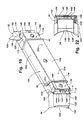
- FIG. 2 is a rear perspective view of the plow assembly of FIG. 1;
- FIG. 3 is a front elevation of the plow assembly of FIGS. 1 and 2;
- FIG. 4 is a rear elevation of the plow assembly of FIGS. 1-3, with the fluid cylinders, hinge and slide assembly shown in phantom for each of the plow wings;
- FIG. 5 is an end elevation of the plow assembly of FIGS. 1-4;
- FIG. 6 is a cross sectional view taken along the line VI—VI in FIG. 4;
- FIG. 7 is a cross sectional view taken along the line VII—VII in FIG. 23;
- FIG. 8 is a perspective view of a slide member useful with the present invention.
- FIG. 9 is a top plan view of the slide member of FIG. 8;
- FIG. 10 is an end elevation of the slide member of FIGS. 8 and 9;
- FIG. 11 is a front elevation of the slide member of FIGS. 8-10;
- FIG. 12 is a perspective view of the slide member and plow wing of the present invention, with portions of the slide member cut away to show additional details;
- FIG. 13 is a rear elevation of the slide member and plow wing of FIG. 12;
- FIG. 14 is a top plan view of the plow assembly of the present invention with the plow wings extended, with the fluid cylinders, hinge and slide assembly shown in phantom for each of the plow wings;
- FIG. 15 is a rear perspective view of the plow assembly of FIG. 14, showing the mounting brackets for mounting the plow to a support frame at the vehicle;
- FIG. 16 is a front elevation of the plow assembly with the wings extended as shown in FIGS. 14 and 15;
- FIG. 17 is a rear elevation of the plow assembly of FIGS. 14-16, with the fluid cylinders, hinge and slide assembly shown in phantom for each of the plow wings;
- FIG. 18 is a top plan view of the plow assembly of the present invention with the plow wings extended and angled forwardly forming a generally U-shaped plow, with the fluid cylinders, hinge and slide assembly shown in phantom for each of the plow wings;
- FIG. 19 is a rear perspective view of the plow assembly with the wings extended and angled forwardly as shown in FIG. 18;
- FIG. 20 is a front elevation of the plow assembly of FIGS. 18 and 19;
- FIG. 21 is a rear elevation of the plow assembly of FIGS. 18-20, with the fluid cylinders, hinge and slide assembly shown in phantom for each of the plow wings;
- FIG. 22 is an end elevation of the plow assembly of FIGS. 18-21;
- FIG. 23 is a top plan view of the plow assembly of the present invention with one of the plow wings extended and angled forwardly and the other plow wing in the retracted position, with the fluid cylinders, hinge and slide assembly shown in phantom for each of the plow wings; and
- FIG. 24 is a schematic illustration of the hydraulic system for operation of the adjustable plow assembly of the present invention.
- an adjustable wing plow assembly 10 includes a reinforced main plow 12 pivotally mounted on a support frame 14 via an intermediate support 16 .
- extendable plow wings 22 , 24 which are each moved by at least one and, in certain embodiments, two actuators, such as fluid power cylinders 200 , 202 , 204 and 206 , remotely controlled from the cab of the pickup truck, dozer, or other vehicle on which the plow assembly 10 is mounted.
- Wings 22 , 24 are independently slidably movable between retracted positions as shown in FIGS. 1-5, fully extended positions as shown in FIGS.
- Plow assembly 10 is primarily adapted for plowing snow when attached to the front of a transport vehicle such as a pickup truck, utility vehicle, tractor, or the like via support frame 14 .
- a transport vehicle such as a pickup truck, utility vehicle, tractor, or the like
- other materials such as sand, dirt, gravel, bark mulch, and the like, can also be moved with the plow.
- plow 12 can be mounted on other vehicles, such as bulldozers, graders or other construction or excavation vehicles, and in other ways besides support frame 14 , such as by vertical supports secured to the rear of the plow as explained more fully below.
- both support frame 14 and intermediate support 16 are similar to the support frame and intermediate support disclosed in commonly assigned U.S. Pat. Nos. 5,638,618 and 5,899,007, which are hereby incorporated herein by reference, such that a detailed discussion of the support frame and intermediate support need not be included herein.
- plow assembly 10 may be mounted to the vehicle via any other means, such as via conventional mounting frames or supports, without affecting the scope of the present invention. Suffice it to say that, as shown in FIG.
- support frame 14 is of the type suitable for attachment to the front of a pickup truck or the like and preferably includes a triangularly shaped, reinforced framework having a base 26 , inwardly tapering sides 28 , 30 leading to a forward apex 32 , and spaced pairs of rearwardly extending support flanges 34 , 36 on base 26 adapted to allow frame 14 to be secured to a suitable hitch assembly on the front of a pickup truck or other vehicle for pivotal movement about a horizontal axis A extending through the support flanges.
- Laterally extending pairs of vertically spaced cylinder support flanges 38 , 40 extend outwardly from the opposite sides 28 , 30 of frame 14 and the outermost support flanges 34 , 36 .
- a pair of extendable, single acting, hydraulic fluid cylinders 42 , 44 are pivotally mounted, one on either side of frame 14 , between cylinder support flanges 38 , 40 and pivot pins 46 , 48 on intermediate support 16 .
- Pins 46 , 48 extend between an upper plate 47 and a spaced lower plate (not shown) of intermediate support 16 .
- Intermediate support 16 (FIG. 1) is an elongated steel beam having a generally U-shaped configuration in cross section, upper plate 47 , the lower plate, a forward plate (also not shown), and pairs of plow mounting flanges 50 welded to the ends of the plates and projecting forwardly toward the rear surface of plow 12 .
- Plow 12 includes rearwardly extending, vertically oriented supports or mounting flanges 54 , 56 extending between flanges 50 , for mounting on horizontal rods 58 , 60 aligned on a common horizontal axis B to allow the entire plow 12 to pivot about that horizontal axis.
- Intermediate support 16 is, in turn, pivotally mounted to apex 32 of support frame 14 by a generally vertically extending pivot pin 62 .
- intermediate support 16 and plow 12 By controlling the extension and retraction of fluid cylinders 42 , 44 , intermediate support 16 and plow 12 , which is mounted thereon, may be moved to a series of angled positions such that plow 12 is swung and angled to the left or right about pivot 62 .
- Plow 12 is biased to an upright position about horizontal axis B on pins 58 , 60 by a series of biasing members such as coil springs 64 which extend between mounting flanges 66 extending upwardly from the top surface of intermediate support 16 and support flanges 68 at the top of rear surface 84 of plow 12 .
- a shock absorber 70 is pivotally mounted between upstanding support flanges 72 on intermediate support 16 and rearwardly extending support flanges 74 on the rear surface 84 of plow 12 .
- Shock absorber 70 and springs 64 are shown in FIG. 1 with their middle portions cut away to reveal additional details of plow assembly 10 , as discussed below.
- Shock absorber 70 dampens the pivotal movement of plow assembly 10 about horizontal axis B on pins 58 , 60 during plowing when the plow encounters an obstacle along the surface being plowed thereby causing the plow 12 with wings 22 , 24 to tip or pivot forwardly against the bias of springs 64 .
- Rearward pivoting of the plow about axis B on pins 58 , 60 is limited by the rear, vertical edges of flanges 54 , 56 which engage the forward plate on intermediate support 16 . Forward pivotal movement is limited by springs 64 and shock absorber 70 .
- support frame 14 is pivotally secured to a horizontal axis A on a vehicle via support flanges 34 , 36 , the entire support frame 14 , intermediate support 16 and plow 12 including extendable wings 22 , 24 may be lifted away from the ground or other support surface via a retractable hydraulic cylinder 76 (FIG. 24 ).
- Lift cylinder 76 is preferably pivotally mounted between the support frame 14 and a suitable mounting point on the pickup truck or other vehicle.
- plow 12 may alternately mount directly to a support frame via the mounting brackets shown in FIG. 15 .
- Such mounting brackets may be suitable for mounting the plow to a dozer or other excavation or construction vehicles.
- a central pivot bracket or collar 94 pivotally receives a pivot pin or axle (not shown) at a forward end of the support frame (also not shown).
- a pair of actuator mount flanges 95 are positioned at each side of central bracket 94 and pivotally mount an end of a pair of side actuators, which are operable to pivot plow 12 about the pivot pin similar to actuators 42 , 44 discussed above.
- a pair of brackets 97 may also be mounted at the rear of plow 12 to provide attachment for a fore/aft tilt restraint linkage or the like. Such a bracket could also accommodate a side tilt actuator or cylinder (not shown). Additional plates or flanges 96 may be provided to strengthen and support plow 12 . Other mounting means may be implemented, without affecting the scope of the present invention.
- main plow 12 is preferably an elongated, rectilinear steel moldboard 80 having a concave front surface 82 and a convex rear surface 84 .
- a replaceable elongated, rectilinear plow blade 90 Secured to a lower flange which extends along the lower edge of moldboard 80 is a replaceable elongated, rectilinear plow blade 90 , which may be secured to moldboard 80 by fasteners (not shown) having countersunk heads which are flush with the front surface of blade 90 to prevent interference with the material being plowed.
- moldboard 80 provides a generally continuous, uninterrupted front surface 82 , such that the material being moved by the plow moves upwardly along moldboard 80 from plow blade 90 and continues along front surface 82 of the moldboard without interruption.
- the right and left ends of moldboard 80 are curved (FIG. 3) so as to align with the front surface of wings 22 , 24 when the plow wings 22 , 24 are extended outwardly and angled forwardly as shown, for example, in FIGS. 18-22.
- the rear surface 84 of moldboard 80 is preferably reinforced with supports or mounting flanges (not shown) on either side of its center, as well as end flanges 81 welded to rear surface 84 adjacent either end.
- Moldboard 80 is preferably formed of steel or other strong, durable material. However, it is envisioned that the rectilinear moldboard 80 may alternately be formed in two sections, similar to the moldboard disclosed in U.S. Pat. No. 5,899,007.
- moldboard 80 may include a first, steel section which extends up from the top of plow blade 90 , and a second, upper, curved section of the moldboard, which is preferably formed from a polymeric sheet material such as opaque ultra high molecular weight (UHMW) polyethylene or clear polycarbonate.
- UHMW opaque ultra high molecular weight
- material to be plowed such as snow, sand, dirt, gravel or other plowable material
- material to be plowed engages the plow blade 90
- it is forced upwardly along the first moldboard section, which bears the principal amount of force causing the material to change directions, while the remainder of the first section and the second section impart a rolling action or a continuation of the change in direction to force the plowed material forwardly as the plow is moved in the same direction.
- Such a polymeric sheet material may save a significant amount of weight in the overall plow assembly, and also may provide the ability to view through the upper section of the plow, especially when the plow assembly is raised to its inoperative position when mounted on the front of a truck.
- moldboard 80 may be unitarily formed of steel or polymeric materials, and may be formed with the plow blade, without affecting the scope of the present invention.
- support skids (not shown) may be mounted at either end of the rear of the main plow assembly.
- moldboard 80 On the rear surface 84 of moldboard 80 is preferably welded a rectangular, steel slide support or housing 100 having a top wall 102 , bottom wall 104 , and rear wall 106 forming a generally U-shaped enclosure. End flanges 81 define a partial outer wall of housing 100 and provide an opening therethrough. As will be explained below, slide support or housing 100 is adapted to receive a generally rectangular inner slide member 170 , 170 ′, best seen in FIGS. 8-13.
- the actuators, slides, hinges and wings may be mounted along the rear surface 84 of moldboard 80 within an open frame or structure or along support rails or the like positioned along the rear of the plow, such that the slides and wings are otherwise movably mounted along the rear of the plow, without affecting the scope of the present invention.
- Mounting flanges 54 , 56 and the plow reinforcing flanges may extend over top wall 102 , along rear wall 106 and thereafter along bottom wall 104 of housing 100 and are welded thereto to reinforce the entire assembly.
- FIGS. 2-14 and 16 - 23 are shown with the mounting and reinforcing flanges removed to assist in clarifying the details of the present invention.
- a center support plate or flange 86 is welded to rear surface 84 of moldboard 80 and/or to walls 102 , 104 and/or 106 of housing 100 (FIGS. 4, 14 , 17 , 18 and 21 ).
- a pair of actuator mounting flanges 208 , 210 and 208 ′, 210 ′ are welded to center plate 86 and extend laterally outwardly from both sides of plate 86 .
- Flanges 208 , 210 and 208 , 210 ′ provide a corresponding pair of vertically spaced apertures 201 and 201 ′ for mounting actuators 200 , 202 to plow 12 , as discussed below.
- Flanges 208 , 210 and 208 ′, 210 ′ may also or alternately be welded or otherwise secured to housing 100 and/or rear surface 84 of moldboard 80 , without affecting the scope of the present invention.
- each plow wing extension 22 , 24 is a substantial mirror image of the other. Because the plow wings are substantially identical, only one will be described in detail herein, namely, plow wing 22 . Substantially the same elements are included in plow wing extension 24 but are shown with prime numerals.
- Plow wing extension 22 includes a moldboard section 120 having a radius of curvature substantially the same as that for moldboard 80 and extending generally parallel to moldboard 80 when mounted on the plow assembly.
- a steel extension blade 124 also known as a cutting edge or wear edge, is removably secured to the front surface of the lower edge of moldboard 120 and extends generally parallel to plow blade 90 , as shown in FIG. 5 .
- Blade 124 may be secured to moldboard 120 via any known means, such as via fasteners or the like, and may be formed as part of moldboard 120 , without affecting the scope of the present invention. Blade 124 engages the plowed surface during plowing and may be repaired or replaced when worn.
- a generally vertical reinforcing wall or flange 126 extends along the outermost edge 128 of wing extension moldboard 120 .
- the innermost edge 130 of moldboard 120 is generally curved outwardly, as best shown in FIG. 13 .
- housing 132 Extending parallel to the upper and lower edges of wing extension 22 on the rear surface thereof is a tapered housing 132 which may have a series of weight reducing, generally rectangular openings (not shown) formed therethrough.
- Housing 132 is preferably formed from sheet steel bent into a generally U-shaped configuration and welded to the rear surface of moldboard 120 .
- Housing 132 is slightly smaller than both outer housing 100 and inner slide member 170 , as will be understood from FIG. 19 .
- Housings 132 , 132 ′ preferably extend only along a portion of the rear of their respective moldboards, such that a substantial area of the rear surfaces of moldboards 120 , 120 ′, and thus the rear wing structure, are exposed. This provides improved visibility of the blade cutting edges of the wings as they contact the ground, thereby providing improved control of the quality of the finished grade to the operator of the plow.
- a vertical support plate 140 is welded to the edges of the housing 132 at the inner edge of plow wing 22 .
- a vertically oriented hinge support tube or hinge cylinder 142 welded to plate 140 .
- Intermediate the ends of support tube 142 are a pair of spaced hinge plates 144 , 146 which are welded to both support tube 142 and support plate 140 and extend parallel to one another outwardly away from the inner edge of the wing extension.
- a vertical hinge pivot axis X is provided by support tube 142 while a fluid cylinder pivot axis Y is provided by aligned apertures 148 extending through hinge plates 144 , 146 .
- Hinge pivot axis X is offset from fluid cylinder pivot axis Y by a predetermined distance creating a moment arm providing torque for pivoting the wing extension on its hinge axis X, as will be explained more fully below.
- each plow wing extension 22 , 24 is pivotally mounted to the end of a generally rectangular slide member 170 , 170 ′, only one of which is described in detail herein.
- the subassemblies 160 , 160 ′ of slide member 170 and wing extension 22 , or slide member 170 ′ and wing extension 24 (FIGS. 8 - 13 ), are both adapted to be slidably mounted telescopingly within housing 100 on the rear surface of main plow moldboard 80 to allow extension, retraction and forward angling of the plow wing extensions 22 , 24 by actuators 200 , 202 , 204 and 206 , as referenced above and as explained more fully below.
- each slide member 170 , 170 ′ is an elongated beam or frame having a generally rectangular cross section, preferably formed from welded steel, and including a top wall 172 , rear wall 174 , bottom wall 176 , and a front wall 178 .
- Rear walls 174 , 174 ′ may include elongated, closed slots 212 (FIGS. 6 and 8) which are adapted to receive a cylindrical stop pins 214 (FIGS. 2 and 19) projecting from housing 100 , which limit the extension and retraction of the slide members, and thus, wing extensions 22 , 24 , as explained below.
- a pair of parallel hinge plates 179 , 180 are welded to the top and bottom walls 172 , 176 , respectively, of slide member 170 .
- Hinge plates 179 , 180 project outwardly from the outer end of slide member 170 , and provide vertically spaced, vertically aligned apertures 182 a and 182 b in the projecting portion of the hinge plates.
- three actuator support plates 186 , 188 , 190 are secured between forward wall and rear wall of slide members 170 , 170 ′.
- Support plates 186 , 188 , 190 include two pair of vertically aligned apertures 192 a, b and 194 a, b which receive pivot pins for mounting the outer end and inner end of the pair of actuators or fluid cylinders for operating the wing extensions, as will be more fully explained below.
- plow wing extensions 22 , 24 are pivotally mounted to the outer ends of elongated slide members 170 , 170 ′, by means of hinge plates 179 , 180 .
- a hinge pin 196 extends through vertically aligned apertures 182 a , 182 b and through cylindrical hinge tube 142 along axis X to provide the hinged movement.
- Plow wing 22 therefore pivots on axis X from a position in which moldboard 120 is generally rectilinearly aligned with slide member 170 to a forwardly angled position in which moldboard 120 extends at an obtuse angle to slide member 170 (FIG. 19 ).
- slide member 170 or housing 100 may include elongated, synthetic wear pads or strips 108 (FIG. 6) secured to the outer surface of one or more walls of slide member 170 or to the inner surface of one or more walls of housing 100 to slidably support slide member 170 inside housing 100 and to maintain the slide members in alignment with the rear surface of 84 of moldboard 80 .
- wear pads 108 are formed from ultra high molecular weight (UHMW) polyethylene, although other materials, such as Teflon, steel and the like could also be used.
- UHMW ultra high molecular weight
- one or more of the walls of slide member 170 may engage the inner surface of housing 100 to slidingly support the slide member 170 within the housing.
- suitable lubricants may also be used to enhance sliding of the slide member along the slide support or housing.
- the subassemblies 160 , 160 ′ of slide members 170 , 170 ′ and their pivotally attached plow wing extensions 22 , 24 , respectively, are telescopingly mounted within the interior of the slide support or outer housing 100 for sliding rectilinear movement within the outer housing along a common axis.
- the slide members may slide along one or more wear pads 108 within housing 100 .
- the slide members, actuators and wings may be mounted along the rear of the plow via other slide support means, such as an open frame or upper and lower support rails or the like, without affecting the scope of the present invention.
- Wings 22 , 24 are extended and pivoted via actuators 200 , 202 and 204 , 206 , respectively.
- Actuators or fluid cylinders 200 , 202 include extendable members 200 a , 202 a , such as piston rods or the like, while actuators 204 , 206 include extendable members or rods 204 a , 206 a .
- Actuators 200 , 202 are longer and extend rods 200 a , 202 a a greater distance than actuators 204 , 206 and rods 204 a , 206 a . As shown in FIGS.
- actuators 200 , 202 extend into the interior space of slide members 170 , 171 ′ from their inner end, while fluid cylinders 204 , 206 are mounted within the interior space of slide members 170 , 170 ′ and extend out of the outer end of the slide members for engagement with the plow wings.
- each slide member 170 , 170 ′ is accomplished by a power source or actuator 200 , 202 , preferably a pair of independent, overlapping, double acting, hydraulic fluid cylinders.
- the nonextendable ends of actuators 200 , 202 are pivotally mounted between the pair of support plates 208 , 210 and 208 ′, 210 ′ via pivot pins 201 a (FIGS. 18 and 21 ), such that actuators 200 , 202 are generally aligned with one another along the rear surface of the plow and within housing 100 .
- An aperture (not shown) may be provided through rear wall 106 of housing 100 adjacent to plates 208 , 210 and 208 ′, 210 ′ for access to the actuators.
- extendable piston rods 200 a , 202 a are pivotally secured to slide member 170 , 170 ′ by pivot pins 205 mounted through vertically aligned apertures 192 a , 192 b or 192 a ′, 192 b ′ of support plates 188 , 186 or 188 ′, 186 ′, respectively.
- pivot pins 205 mounted through vertically aligned apertures 192 a , 192 b or 192 a ′, 192 b ′ of support plates 188 , 186 or 188 ′, 186 ′, respectively.
- two double acting, hydraulic fluid cylinders are shown for use in slidably moving the slide members along the plow, it is within the scope of the invention to utilize other power sources to extend or retract the plow wings, such as a single actuator for each wing, whereby extension of the actuator first extends the wing to the extended position and further extension of the actuator pivots the wings toward the forwardly angled position.
- both of the plow wings may be movable via a single, double acting hydraulic cylinder which has extendable rods projecting from either end, or by other means for extending or retracting the wings with respect to the plow.
- Other extendable means may be implemented, such as, for example, threaded rods rotated by at least one electric motor or a pulley and cable system, to move slides 170 , 170 ′ outwardly or inwardly for extension and retraction, without affecting the scope of the present invention.
- actuators or fluid cylinders 204 , 206 are respectively pivotally connected to slide member 170 , 170 ′ via pivot pins 203 passed through vertically aligned apertures 194 a , 194 b or 194 a ′, 194 b ′ of support plates 190 , 188 or 190 ′, 188 ′, and through the end of the fluid cylinders.
- the outer ends of extendable piston rods 204 a , 206 a are pivotally connected via hinge pins 207 passed through the vertically aligned apertures 148 , thereby defining axis Y in hinge plates 144 , 146 or 144 ′, 146 ′.
- the respective fluid cylinder 200 and/or 202 is activated by means of a hydraulic control system, described more fully below, to extend piston rod 200 a , 202 a , thereby moving slide member 170 or 170 ′ rectilinearly outwardly along with wings 22 or 24 , and preferably on wear pads 108 .
- Fluid cylinders 200 , 202 move slide members 170 , 170 ′ outwardly to their full extension while moldboard 120 remains substantially parallel to the front surface of main plow 12 . Sliding movement of slide member 170 , 170 ′ may be limited by the projecting, cylindrical stop members 214 which are mounted at housing 100 and are in alignment with the corresponding slots 212 in the slide members.
- the hydraulic cylinders 200 , 202 may provide a positive stop of their extension and retraction at their full extension or retraction, whereby the pistons may “bottom out” within the cylinder to limit extension/retraction of the piston and rod assembly at a desired position.
- Extension of slide member 170 , 170 ′ thus continues until a switch is thrown to stop extension of actuator 200 , 202 or until the stops engage the inner ends of the slots, or is otherwise stopped, thereby stopping further outward extension of the plow wings.
- other means for limiting outer movement of the slide members relative to plow 12 may be implemented, without affecting the scope of the present invention.
- the outer wing ends 128 , 128 ′ are spaced outwardly of the retracted position and of the outer ends 18 , 20 of main plow moldboard 80 .
- one of the actuators 204 , 206 are activated to pivot the wings about pivot pins 196 , 196 ′ until the wings are angled forwardly at an obtuse angle to the main plow moldboard, as shown in FIGS. 18-23, such that the entire plow may have a U-shaped configuration (if both wings are pivoted forwardly as shown in FIGS. 18 - 22 ).
- Extension of pivotally mounted fluid cylinders 204 , 206 causes rotation of wing extensions 22 , 24 forwardly about hinge pins 196 , 196 ′ due to the distance between pivot axes X and Y, as shown in FIGS.
- ends 18 , 20 of main plow moldboard 80 are curved to substantially engage the forward surface of partial moldboard 120 of plow wings 22 , 24 along an inward end thereof.
- the outward curved edges 18 , 20 of moldboard 80 allows the plow wings to be pivoted to the forward position without interference between those edges and the plow wings.
- edges 130 , 130 ′ of wings 22 , 24 are curved inwardly to avoid interference with the actuators, housings and slide members as the wings are pivoted toward their forwardly angled positions. Hydraulic pressure within cylinders 204 , 206 keeps the plow wings in the forwardly pivoted positions for pushing or carrying snow or other plowable material such that the material does not slip off the ends of the plow assembly.
- the plow operator may simply operate a single switch to extend one or both of fluid cylinders 200 , 202 after which the fluid pressure is automatically transferred to the second fluid cylinder or cylinders 204 , 206 , respectively, such that the slide member is fully extended and the wing extensions are then pivoted forwardly all in a continuous movement or motion.
- the hydraulic pressure in the fluid cylinders resists rearward pivoting of the forwardly angled wing extensions during plowing.
- extreme pressure created within the fluid cylinders 204 , 206 would be relieved through the hydraulic system to prevent rupture of hydraulic lines or damage to any of the components.
- the plow assembly may be used in its retracted position to plow snow or other plowable materials when either centered or angled to the left or right, the preferred length of such plow in the retracted position being approximately eight feet.
- cylinders 200 , 202 can be extended simultaneously or independently of one another such that wing extensions 22 , 24 are in their fully extended positions as shown in FIGS. 14-17 and the plow may also be used either centered or angled left or right by extending one or the other of fluid cylinders 42 , 44 (FIG. 1 ). With the wing extensions fully extended, the plow assembly has a preferred overall length of approximately eleven feet. Further, as shown in FIGS.
- extension of cylinders 204 and/or 206 causes forward pivotal movement of plow extensions 22 and/or 24 to the positions shown therein, thereby providing a substantial U-shape for the plow assembly allowing snow or other material to be pushed or carried from one position along a horizontal surface to another without the material slipping off the ends of the plow assembly. It is also possible to extend only one or the other of wing extensions 22 , 24 such that the plow may be used with only one end extended or pivoted forwardly (as shown in FIG. 23 ), or one end extended with the opposite end extended and pivoted forwardly.
- each pair of fluid cylinders 200 , 204 or 202 , 206 is controlled by its own respective set of solenoid operated hydraulic valves and cooperating hydraulic relief valves or sequencing valves via electrical switches mounted in the cab of the plowing vehicle.
- a conventional hydraulic pump 250 creates hydraulic line pressure which is directed by an electric solenoid operated spool valve 252 a or 252 b through line 254 a or 254 b to the inner end of fluid cylinder 200 or 202 , thereby extending piston rod 200 a or 202 a upon closure of an appropriate electrical switch in the vehicle cab by the vehicle/plow operator. This shifts solenoid valve 252 a or 252 b to the left or right, respectively, in FIG. 24 .
- piston rod 200 a or 202 a is fully extended, the buildup of hydraulic pressure in line 254 a or 254 b activates hydraulic relief valve or sequencing valve 256 a or 256 b to allow fluid pressure through hydraulic line 258 a or 258 b to fluid cylinder 204 or 206 , thereby causing extension of piston rod 204 a or 206 a , and thereby pivoting plow wing 22 or 24 forwardly as shown in FIG. 24 .
- the plow operator may only need to depress a single switch causing fluid pressure to extend cylinder 200 or 202 and then subsequently cylinder 204 or 206 through the operation of relief valves 256 a , 256 b .
- Release of the switch causes solenoid valves 252 a , 252 b to return to their centered positions thereby holding fluid cylinders 200 , 204 , and/or 202 , 206 in their extended and forwardly pivoted positions.
- solenoid valve 252 a or 252 b is activated in the reverse direction by moving or depressing the appropriate electrical switch shifting the spool valve to the right or left, respectively, in FIG. 24 .
- Hydraulic pressure is directed through lines 260 a , 260 b to the outer end of fluid cylinder 204 or 206 , causing retraction of piston rod 204 a or 206 a and pivoting wing 22 or 24 to its extended position from its forwardly angled position.
- the electronic switch is operable to deactivate the respective actuator 200 , 202 in response to a threshold amount of movement of the plow wing (corresponding to the fully extended position or fully retracted position of the plow wing) along the rear surface of the plow.
- the micro switches may each include a flexible strap which extends through an aperture in housing 100 and flexes away from the plunger on an electrical switch when slide member 170 , 170 ′ is extended, but is flexed into contact with the switch plunger when the slide member is retracted.
- stop members or limit switches may be implemented to deactuate one actuator 200 , 202 , and subsequently or substantially simultaneously actuate the other actuator 204 , 206 , such that the plow wings are smoothly and continuously movable between the retracted and forwardly angled positions, without affecting the scope of the present invention.
- valving for operating the fluid cylinders 42 , 44 to pivot the plow assembly about support 14 and axis 62 to the left or right is provided through solenoid operated valve 266 which is shifted to the right by operation of an electrical switch to angle the plow assembly to the left with fluid cylinder 42 through hydraulic line 270 a , and shifted to the right through the reversal of the same switch to angle the plow assembly to the right with fluid cylinder 44 through hydraulic line 270 b .
- Appropriate relief valves 272 , 274 are connected, respectively, to lines 270 a , 270 b in the event pressure on the plow during plowing forces the plow in the opposite pivotal direction and creates extreme pressure within the hydraulic system.
- a solenoid operated valve 276 and an electrically operated check valve 278 may be shifted to the left to activate and extend the lift cylinder 76 in the event such a cylinder is included on the support 14 .
- Check valve 279 retains cylinder 76 in its extended position.
- a solenoid operated valve 277 and a check valve 279 are shifted to the left, and check valve 278 holds cylinder 76 in its retracted position.
- the present invention provides a plow assembly which includes extendable and retractable wings which are also pivotable forwardly with respect to the main plow blade. Because the wings are mounted and movable along the rear surface of the main plow, the plow moldboard may provide a continuous, uninterrupted front surface for pushing material. By positioning the plow wings rearward of the main plow, the hinge and slide components of the plow wings of the present invention are protected behind the plow and thus are not exposed to the material being moved by the plow. This substantially improves protection of the movable components of the plow assembly, while providing a continuous front surface of the plow blade.
- each plow wing may be accomplished via extension of a single actuator.
- an actuator may extend a certain distance to move the plow wing outwardly along the rear surface of the plow to a point of maximum allowable extension, whereby further movement is limited by a stop, such as stop pins or the like. Because subsequent extension of the plow wing is substantially precluded, further extension of the single cylinder will cause pivotal movement of the wing about the pivot axis toward the forwardly angled position.
- Pivotal movement of the wing prior to full extension of the wing is substantially precluded due to the plow wing being positioned along a rear surface of the plow, which prevents forward pivoting of the wing until the wing is extended beyond the outer edge of the plow.
- the actuator When the actuator is retracted, the plow wing will pivot back toward its aligned position as it is pulled inwardly by the actuator until the plow wing is again fully aligned and retracted with respect to the plow.
- the plow wing may include a mechanical locking mechanism (not shown), similar to the locking mechanism disclosed in U.S. Pat. Nos. 5,638,618 and 5,899,007, which prevents pivotal movement of the plow wing until the plow wing is first fully extended from the plow.
- the locking mechanism may function to prevent inward retraction of the plow wing along the plow until after the plow wing has been fully pivoted back into its aligned position with respect to the plow.
- the locking mechanism may comprise any means for precluding rotation of the plow wing until full extension and then preventing retraction of the plow wing until full rotation of the plow wing back to the aligned position occurs, without affecting the scope of the present invention.
- one or more springs or biasing members may be mounted between the slide member and the plow, and exert a biasing force to resist pivotal movement of the plow wing until the wing is extended and the biasing force is overcome by the actuator (to avoid potential binding of the wing if it pivots while still in an at least partially retracted position along the rear of the plow).
- the biasing force is selected such that the slide members are fully extendable until they contact a stop, and then further extension by the actuator overcomes the spring force and pivots the plow wing forwardly.
- Such a spring may also function to absorb the shock or impact force of an obstacle impacting the rear of an extended plow wing as the plow is moving in reverse, thereby protecting the actuators from such a shock.
- the actuators for the plow assembly of the present invention may comprise other means for extending and retracting or for pivoting.
- the actuators 204 , 206 may comprise an electronic or hydraulic rotary motor or other means for imparting relative rotation between two components about a hinge or pivot axis.
- the actuators 200 , 202 , 204 and/or 206 may comprise a linear actuator with a ball and screw mechanism, or may comprise a rotary motor with a gear which engages a timing belt or other toothed, movable member, such that rotation of the motor imparts a generally linear movement of the movable member, thereby extending or pivoting the plow wings. It is further envisioned that the actuators may even be manually operated mechanical devices, such as a hand crank or lever, which may be operable to linearly or rotationally move one or both of the plow wings with respect to the main plow. Other means for imparting a linear or rotational movement to the plow wings may be implemented without affecting the scope of the present invention. In situations where an hydraulic cylinder is not implemented, an additional stop or locking mechanism may be desired to lock or retain the plow wings in the desired position, such that the wings are not pivoted when resistance is encountered by the plow as it is moved by the vehicle.
- an overhead beam may include downwardly extending rods or other supports which engage rear mounting flanges 54 , 56 from above to support the assembly in the normal horizontal position shown in the drawings.
- Other supports such as bulldozer type support arms extending from the rear of the plow to a support frame on a vehicle may also be used with this plow assembly.
Abstract
Description
Claims (50)
Priority Applications (2)
| Application Number | Priority Date | Filing Date | Title |
|---|---|---|---|
| US09/689,004 US6442877B1 (en) | 2000-10-12 | 2000-10-12 | Plow with rear mounted, adjustable wing |
| CA002358359A CA2358359C (en) | 2000-10-12 | 2001-10-02 | Plow with rear mounted, adjustable wing |
Applications Claiming Priority (1)
| Application Number | Priority Date | Filing Date | Title |
|---|---|---|---|
| US09/689,004 US6442877B1 (en) | 2000-10-12 | 2000-10-12 | Plow with rear mounted, adjustable wing |
Publications (1)
| Publication Number | Publication Date |
|---|---|
| US6442877B1 true US6442877B1 (en) | 2002-09-03 |
Family
ID=24766670
Family Applications (1)
| Application Number | Title | Priority Date | Filing Date |
|---|---|---|---|
| US09/689,004 Expired - Lifetime US6442877B1 (en) | 2000-10-12 | 2000-10-12 | Plow with rear mounted, adjustable wing |
Country Status (2)
| Country | Link |
|---|---|
| US (1) | US6442877B1 (en) |
| CA (1) | CA2358359C (en) |
Cited By (55)
| Publication number | Priority date | Publication date | Assignee | Title |
|---|---|---|---|---|
| US20040205985A1 (en) * | 2003-03-31 | 2004-10-21 | Schmeichel Charles M | Self-adjusting snow plow |
| US20040216333A1 (en) * | 2003-05-02 | 2004-11-04 | Quenzi Philip J. | Adjustable wing plow |
| US20050229437A1 (en) * | 2004-03-30 | 2005-10-20 | Clinton Nesseth | Double wing scraper |
| US20060230648A1 (en) * | 2003-02-25 | 2006-10-19 | Gianluca Malacrino | Bucket or scoop with adjustable capacity |
| US20070056193A1 (en) * | 2001-11-12 | 2007-03-15 | Schmeichel Charles M | Snow plow having wear minimizing apparatus |
| US20070062071A1 (en) * | 2001-11-12 | 2007-03-22 | Charles Schmeichel | Snow plow having pivotal mounting apparatus |
| US20070062073A1 (en) * | 2001-11-12 | 2007-03-22 | Charles Schmeichel | Multifunctional plow blade positioning apparatus and method |
| US20070062072A1 (en) * | 2001-11-12 | 2007-03-22 | Charles Schmeichel | Snow plow having two-piece mold board |
| US20070089327A1 (en) * | 2005-10-21 | 2007-04-26 | Watson Gary E | Plow with blade wing |
| US20070256334A1 (en) * | 2001-11-12 | 2007-11-08 | Charles Schmeichel | Snow plow having internally reinforced mold board |
| US20080155865A1 (en) * | 2006-12-31 | 2008-07-03 | Mills David W | Snowplow system, snow deflector apparatus and kit |
| US20080235996A1 (en) * | 2007-03-29 | 2008-10-02 | Degelman Industries Ltd. | Hinged plow and scraper blade |
| US7584557B1 (en) | 2004-06-09 | 2009-09-08 | Degelman Industries Ltd. | Snow plowing system |
| US20090307942A1 (en) * | 2008-06-17 | 2009-12-17 | Gamble Ii Robert N | Snow Plow Rebound Apparatus |
| US20090307944A1 (en) * | 2008-06-17 | 2009-12-17 | Buckbee Mark D | Removable and storable wings for a snow plow blade and snow removal system used therewith |
| US20090307935A1 (en) * | 2008-06-17 | 2009-12-17 | Stevens Mike M | Plow Including Independently Moveable Wings |
| EP2154294A1 (en) * | 2008-08-05 | 2010-02-17 | Destia Oy | Extendible scraper blade |
| US7669353B2 (en) | 2001-11-12 | 2010-03-02 | Agri-Cover, Inc. | Snow plow having hitch tongue connecting member |
| US7676963B2 (en) | 2001-11-12 | 2010-03-16 | Agri-Cover, Inc. | Snow plow including mold board having back plate |
| US20100064554A1 (en) * | 2008-09-12 | 2010-03-18 | Jim Ropog | Three position wing for snowplow |
| US7681335B2 (en) | 2001-11-12 | 2010-03-23 | Agri-Cover, Inc. | Snow plow having attachable biasing member |
| US7681337B2 (en) | 2005-10-21 | 2010-03-23 | Batesville Services, Inc. | Plow with blade wing |
| US7735247B2 (en) | 2001-11-12 | 2010-06-15 | Agri-Cover, Inc. | Snow plow for all terrain vehicle |
| US7735245B2 (en) | 2001-11-12 | 2010-06-15 | Agri-Cover, Inc. | Snow plow having catch structure |
| US20100199527A1 (en) * | 2007-09-25 | 2010-08-12 | Assaloni.Com S.P.A. | Extensible Snowplough Blade |
| US8037625B2 (en) | 2003-03-31 | 2011-10-18 | Agri-Cover, Inc. | Snow plow having pivotal mounting apparatus |
| US8061063B2 (en) | 2008-06-17 | 2011-11-22 | Sno-Way International, Inc. | Plow wing blade |
| US20130185962A1 (en) * | 2012-01-25 | 2013-07-25 | Cives Corporation | Finger snow plow with extension |
| US8607482B2 (en) | 2011-02-28 | 2013-12-17 | Douglas Dynamics, L.L.C. | Plow with pivoting blade wing(s) |
| US20140083725A1 (en) * | 2012-09-27 | 2014-03-27 | Cnh America Llc | Bulldozer folding blade |
| US8850724B2 (en) | 2013-02-15 | 2014-10-07 | Douglas Dynamics, L.L.C. | Plow with pivoting blade wing |
| US8875419B2 (en) | 2001-11-12 | 2014-11-04 | Agri-Cover, Inc. | Snow plow |
| US8887413B2 (en) * | 2012-02-13 | 2014-11-18 | Thomas Andrew Miller | Expanding material box for equipment |
| US9085860B2 (en) | 2012-09-04 | 2015-07-21 | Universal Truck Equipment, Inc. | Wing plow post |
| US9255371B1 (en) * | 2013-07-01 | 2016-02-09 | Joshua Jordan | Vehicle pulled snow scraper systems |
| US9353495B2 (en) | 2011-07-29 | 2016-05-31 | Henderson Products, Inc. | Wing plow with rotatable floating connection |
| US9428866B2 (en) | 2014-09-23 | 2016-08-30 | Nordco Inc. | Segmented railway regulator blade |
| EP3049583A4 (en) * | 2013-09-26 | 2017-05-24 | 9277-9347 Québec Inc. | Equipment for forming surfaces, method of manufacture and use of the equipment for forming surfaces and mobile unit including the equipment for forming surfaces |
| US9752293B2 (en) | 2012-09-04 | 2017-09-05 | Universal Truck Equipment, Inc. | Wing plow post |
| WO2018141021A1 (en) * | 2017-02-02 | 2018-08-09 | Excavator Innovations Pty Ltd | A bucket for earthmoving machines |
| US10053826B1 (en) | 2014-12-12 | 2018-08-21 | Alamo Group Inc. | Wing plow apparatus |
| US10119233B2 (en) | 2016-03-31 | 2018-11-06 | Stonebrooke Equipment, Inc. | Plow assembly with cushioning attachment |
| US10358782B2 (en) | 2016-06-28 | 2019-07-23 | Stonebrooke Equipment, Inc. | Plow assembly with wings |
| US10435864B2 (en) | 2016-02-01 | 2019-10-08 | Stonebrooke Equipment Inc. | Plow assembly with valve system for wings |
| US20210285170A1 (en) * | 2020-03-10 | 2021-09-16 | Betts Platinum Group, PLLC, dba J-Tech | Debris Mover for Mounting on Highway Trucks |
| US11203852B2 (en) * | 2017-01-05 | 2021-12-21 | 9407-4895 Quebec Inc. | Scraping device for cleaning a roadway surface |
| EP3940143A1 (en) * | 2020-07-14 | 2022-01-19 | Florian Lagger | Levelling plate |
| US11248354B2 (en) | 2020-03-12 | 2022-02-15 | Ricky A. Weihl | Plow assembly |
| US11293149B2 (en) * | 2019-03-08 | 2022-04-05 | Caterpillar Paving Products Inc. | Stiffened screed extender tube |
| US11459717B2 (en) * | 2019-12-18 | 2022-10-04 | 9091-4532 Québec Inc. | Snow plow extension slide |
| US11466418B2 (en) * | 2018-12-28 | 2022-10-11 | Meyer Products, Llc | Adjustable snowplow |
| US11466417B2 (en) | 2020-03-12 | 2022-10-11 | Ricky A. Weihl | Plow assembly |
| WO2023073278A1 (en) * | 2021-10-27 | 2023-05-04 | Kiho Palvelut Oy | A snow plough |
| US11926988B2 (en) | 2020-09-22 | 2024-03-12 | Deere & Company | Work machine with automatic pitch control of implement |
| AT18187U1 (en) * | 2022-08-31 | 2024-04-15 | Hochsteiner Johann | Width-adjustable tumbling and sliding shield |
Families Citing this family (1)
| Publication number | Priority date | Publication date | Assignee | Title |
|---|---|---|---|---|
| RU192628U1 (en) * | 2018-11-26 | 2019-09-24 | федеральное государственное бюджетное образовательное учреждение высшего образования "Брянский государственный инженерно-технологический университет" | HYDRAULIC BULLDOZER WORKING EQUIPMENT |
Citations (50)
| Publication number | Priority date | Publication date | Assignee | Title |
|---|---|---|---|---|
| US595202A (en) | 1897-12-07 | Snow-plow | ||
| US1927078A (en) | 1930-02-13 | 1933-09-19 | Root Spring Scraper Company | Snowplow |
| US2218512A (en) | 1938-12-15 | 1940-10-22 | Thomas J Ball | Apparatus for dislodging surface materials |
| US2299451A (en) | 1941-01-27 | 1942-10-20 | Plant Choate Mfg Co Inc | Snow plow |
| US2410543A (en) | 1942-06-22 | 1946-11-05 | Kester George Benjamin | Snow plow |
| US2524329A (en) | 1949-02-07 | 1950-10-03 | Walter B Richardson | Hydraulic wing control |
| US2643470A (en) | 1947-03-14 | 1953-06-30 | George L Kaeser | Wing plow structure |
| DE919474C (en) | 1941-06-07 | 1954-12-06 | Paul Pellischek | Snow plow with swivel walls |
| US3157099A (en) | 1960-09-06 | 1964-11-17 | Ulrich Mfg Co | Earth materials handling apparatus |
| US3250026A (en) | 1963-12-23 | 1966-05-10 | Int Harvester Co | Scraper blade |
| GB1037674A (en) | 1962-05-04 | 1966-08-03 | David Bunce | Snow plough blades |
| US3302317A (en) | 1963-09-26 | 1967-02-07 | Domres Franklin | Grader |
| US3378084A (en) | 1965-01-04 | 1968-04-16 | Ulrich Foundation Inc | Earth materials handling apparatus |
| US3425497A (en) | 1967-07-19 | 1969-02-04 | Caterpillar Tractor Co | Motor grader moldboard |
| US3430706A (en) | 1965-10-22 | 1969-03-04 | John W Marron | Slope cutting attachment for bulldozers |
| US3477151A (en) | 1965-07-06 | 1969-11-11 | Robert C Zanella | Snowplow |
| SE323974B (en) | 1967-01-10 | 1970-05-19 | F Lundholm | |
| US3657828A (en) | 1970-10-23 | 1972-04-25 | Percy D Anderson | Scraper snowplow with pivotal dozer blade |
| US3775877A (en) | 1972-09-28 | 1973-12-04 | E Gove | Backplowing snowplow attachment |
| US3803733A (en) | 1972-10-05 | 1974-04-16 | R Ramsey | Convertible snow plow with slidable closing wings |
| US3807064A (en) | 1972-01-25 | 1974-04-30 | Schmidt Alfred Ing Fa | Snow plow |
| US4019268A (en) | 1976-11-01 | 1977-04-26 | Valley Engineering, Inc. | Apparatus for compacting snow for skiing |
| US4073077A (en) | 1977-01-03 | 1978-02-14 | Essel Albert E | Snowplow blade extension |
| US4074448A (en) | 1976-06-17 | 1978-02-21 | Niemela W Wally | Hinged snowplow, conversion kit, and method therefor |
| US4099578A (en) | 1977-02-10 | 1978-07-11 | Stevens John L | Hinged bulldozer blade |
| US4145825A (en) | 1977-12-16 | 1979-03-27 | Emanual Bertolino | Plow wings |
| US4196532A (en) | 1977-06-16 | 1980-04-08 | Materiel Industriel S.A. | Ballast regulator side plow |
| US4249323A (en) | 1978-06-19 | 1981-02-10 | De Lorean Manufacturing Company | Variable wing plow blade and mounting structure therefor |
| US4275514A (en) | 1980-01-28 | 1981-06-30 | Maura Nicholas J | Snowplow extensions |
| USRE31045E (en) | 1977-01-03 | 1982-10-05 | Snowplow blade extension | |
| US4356645A (en) | 1978-06-19 | 1982-11-02 | De Lorean Manufacturing Company | Variable wing plow blade and mounting structure therefor |
| US4369847A (en) | 1980-01-30 | 1983-01-25 | Mitsubishi Jukogyo Kabushiki Kaisha | Blade assembly |
| US4372617A (en) | 1981-01-05 | 1983-02-08 | Frank J. Zamboni & Co. | Ice edger for ice resurfacing machine |
| US4479312A (en) | 1983-04-11 | 1984-10-30 | Valley Engineering, Inc. | Foldable snow compactor with side wings pivotable behind central blade |
| EP0140139A2 (en) | 1983-09-21 | 1985-05-08 | Erich Prinoth | Smooth shield for a snow vehicle |
| US4614048A (en) | 1985-11-18 | 1986-09-30 | Melby Phillip J | Snow plow apparatus with hinged side blade |
| US4658519A (en) | 1985-08-05 | 1987-04-21 | W. Wally Niemela | Snowplow and implement attachment means for a vehicle |
| US4667426A (en) | 1986-01-27 | 1987-05-26 | Howard Ralph E | Hydraulic wing extension |
| US4723609A (en) | 1985-12-30 | 1988-02-09 | Curtis Floyd F | Double bladed combination scraper |
| US4779363A (en) | 1985-02-27 | 1988-10-25 | Jacques Boutrais | Apparatus adaptable on a pusher vehicle, for the removal and loading of objects such as refuse lying on the ground |
| US4834191A (en) | 1987-12-22 | 1989-05-30 | Vecchio Charles J | Plow for motor grader |
| US4962600A (en) | 1989-09-08 | 1990-10-16 | Zellaha Dennis D | Wing assembly for use with a plow blade |
| US5165191A (en) | 1992-02-25 | 1992-11-24 | William G. Davis | Front end loader attachment convertible between loading bucket and side-shift-angle dozer configurations |
| US5285588A (en) | 1992-07-13 | 1994-02-15 | W. Wally Niemela | Winged plow |
| US5375349A (en) | 1993-04-20 | 1994-12-27 | Jochim; Eric M. | Wing assembly for moldboards of graders and other material moving equipment |
| US5392538A (en) | 1993-06-02 | 1995-02-28 | Geerligs; Gerald J. | Extendable drag plow |
| US5411102A (en) | 1993-09-01 | 1995-05-02 | Nickels; Dean R. | Grader blade attachment for small tractors |
| US5638618A (en) | 1996-06-07 | 1997-06-17 | Blizzard Corporation | Adjustable wing plow |
| US5829174A (en) | 1994-04-08 | 1998-11-03 | Sno-Way International, Inc. | Articulated snowplow system |
| US5899007A (en) | 1996-06-07 | 1999-05-04 | Blizzard Corporation | Adjustable wing plow |
-
2000
- 2000-10-12 US US09/689,004 patent/US6442877B1/en not_active Expired - Lifetime
-
2001
- 2001-10-02 CA CA002358359A patent/CA2358359C/en not_active Expired - Lifetime
Patent Citations (51)
| Publication number | Priority date | Publication date | Assignee | Title |
|---|---|---|---|---|
| US595202A (en) | 1897-12-07 | Snow-plow | ||
| US1927078A (en) | 1930-02-13 | 1933-09-19 | Root Spring Scraper Company | Snowplow |
| US2218512A (en) | 1938-12-15 | 1940-10-22 | Thomas J Ball | Apparatus for dislodging surface materials |
| US2299451A (en) | 1941-01-27 | 1942-10-20 | Plant Choate Mfg Co Inc | Snow plow |
| DE919474C (en) | 1941-06-07 | 1954-12-06 | Paul Pellischek | Snow plow with swivel walls |
| US2410543A (en) | 1942-06-22 | 1946-11-05 | Kester George Benjamin | Snow plow |
| US2643470A (en) | 1947-03-14 | 1953-06-30 | George L Kaeser | Wing plow structure |
| US2524329A (en) | 1949-02-07 | 1950-10-03 | Walter B Richardson | Hydraulic wing control |
| US3157099A (en) | 1960-09-06 | 1964-11-17 | Ulrich Mfg Co | Earth materials handling apparatus |
| GB1037674A (en) | 1962-05-04 | 1966-08-03 | David Bunce | Snow plough blades |
| US3302317A (en) | 1963-09-26 | 1967-02-07 | Domres Franklin | Grader |
| US3250026A (en) | 1963-12-23 | 1966-05-10 | Int Harvester Co | Scraper blade |
| US3378084A (en) | 1965-01-04 | 1968-04-16 | Ulrich Foundation Inc | Earth materials handling apparatus |
| US3477151A (en) | 1965-07-06 | 1969-11-11 | Robert C Zanella | Snowplow |
| US3430706A (en) | 1965-10-22 | 1969-03-04 | John W Marron | Slope cutting attachment for bulldozers |
| SE323974B (en) | 1967-01-10 | 1970-05-19 | F Lundholm | |
| US3425497A (en) | 1967-07-19 | 1969-02-04 | Caterpillar Tractor Co | Motor grader moldboard |
| US3657828A (en) | 1970-10-23 | 1972-04-25 | Percy D Anderson | Scraper snowplow with pivotal dozer blade |
| US3807064A (en) | 1972-01-25 | 1974-04-30 | Schmidt Alfred Ing Fa | Snow plow |
| US3775877A (en) | 1972-09-28 | 1973-12-04 | E Gove | Backplowing snowplow attachment |
| US3803733A (en) | 1972-10-05 | 1974-04-16 | R Ramsey | Convertible snow plow with slidable closing wings |
| US4074448A (en) | 1976-06-17 | 1978-02-21 | Niemela W Wally | Hinged snowplow, conversion kit, and method therefor |
| US4019268A (en) | 1976-11-01 | 1977-04-26 | Valley Engineering, Inc. | Apparatus for compacting snow for skiing |
| US4073077A (en) | 1977-01-03 | 1978-02-14 | Essel Albert E | Snowplow blade extension |
| USRE31045E (en) | 1977-01-03 | 1982-10-05 | Snowplow blade extension | |
| US4099578A (en) | 1977-02-10 | 1978-07-11 | Stevens John L | Hinged bulldozer blade |
| US4196532A (en) | 1977-06-16 | 1980-04-08 | Materiel Industriel S.A. | Ballast regulator side plow |
| US4145825A (en) | 1977-12-16 | 1979-03-27 | Emanual Bertolino | Plow wings |
| US4356645B1 (en) | 1978-06-19 | 1984-11-06 | ||
| US4249323A (en) | 1978-06-19 | 1981-02-10 | De Lorean Manufacturing Company | Variable wing plow blade and mounting structure therefor |
| US4356645A (en) | 1978-06-19 | 1982-11-02 | De Lorean Manufacturing Company | Variable wing plow blade and mounting structure therefor |
| US4275514A (en) | 1980-01-28 | 1981-06-30 | Maura Nicholas J | Snowplow extensions |
| US4369847A (en) | 1980-01-30 | 1983-01-25 | Mitsubishi Jukogyo Kabushiki Kaisha | Blade assembly |
| US4372617A (en) | 1981-01-05 | 1983-02-08 | Frank J. Zamboni & Co. | Ice edger for ice resurfacing machine |
| US4479312A (en) | 1983-04-11 | 1984-10-30 | Valley Engineering, Inc. | Foldable snow compactor with side wings pivotable behind central blade |
| EP0140139A2 (en) | 1983-09-21 | 1985-05-08 | Erich Prinoth | Smooth shield for a snow vehicle |
| US4779363A (en) | 1985-02-27 | 1988-10-25 | Jacques Boutrais | Apparatus adaptable on a pusher vehicle, for the removal and loading of objects such as refuse lying on the ground |
| US4658519A (en) | 1985-08-05 | 1987-04-21 | W. Wally Niemela | Snowplow and implement attachment means for a vehicle |
| US4614048A (en) | 1985-11-18 | 1986-09-30 | Melby Phillip J | Snow plow apparatus with hinged side blade |
| US4723609A (en) | 1985-12-30 | 1988-02-09 | Curtis Floyd F | Double bladed combination scraper |
| US4667426A (en) | 1986-01-27 | 1987-05-26 | Howard Ralph E | Hydraulic wing extension |
| US4834191A (en) | 1987-12-22 | 1989-05-30 | Vecchio Charles J | Plow for motor grader |
| US4962600A (en) | 1989-09-08 | 1990-10-16 | Zellaha Dennis D | Wing assembly for use with a plow blade |
| US5165191A (en) | 1992-02-25 | 1992-11-24 | William G. Davis | Front end loader attachment convertible between loading bucket and side-shift-angle dozer configurations |
| US5285588A (en) | 1992-07-13 | 1994-02-15 | W. Wally Niemela | Winged plow |
| US5375349A (en) | 1993-04-20 | 1994-12-27 | Jochim; Eric M. | Wing assembly for moldboards of graders and other material moving equipment |
| US5392538A (en) | 1993-06-02 | 1995-02-28 | Geerligs; Gerald J. | Extendable drag plow |
| US5411102A (en) | 1993-09-01 | 1995-05-02 | Nickels; Dean R. | Grader blade attachment for small tractors |
| US5829174A (en) | 1994-04-08 | 1998-11-03 | Sno-Way International, Inc. | Articulated snowplow system |
| US5638618A (en) | 1996-06-07 | 1997-06-17 | Blizzard Corporation | Adjustable wing plow |
| US5899007A (en) | 1996-06-07 | 1999-05-04 | Blizzard Corporation | Adjustable wing plow |
Non-Patent Citations (8)
| Title |
|---|
| "Snow Track 440," Publication, Excel Industries, 1989. |
| Commonly Assigned Co-Pending U.S. Patent Application, Serial No. 09/243,908, filed Feb. 3, 1999 by Philip J. Quenzi et al. for Plow Hitch Assembly for Vehicles. |
| Commonly Assigned, Co-Pending U.S. Patent Application, Serial No. 09/689,494, filed Oct. 12, 2000 by Philip J. Quenzi et al., for Adjustable Wing Plow. |
| Commonly Assigned, Co-Pending U.S. Patent Application, Serial No. 09/689,524, filed Oct. 12, 2000 by Philip J. Quenzi et al., for Adjustable Wing Plow with Fixed Pivot. |
| Farm Industry News, vol. 23, No. 7, Jul./Aug. 1990, p. 25. |
| Publication "Still Out Front in Productivity," Excel Industries, Inc., (C) 1988. |
| Publication "Still Out Front in Productivity," Excel Industries, Inc., © 1988. |
| Snow Craft Industries, Inc. Publication, Sedalla, Colorado, published more than one year prior to the filing date of this application -(No date). |
Cited By (99)
| Publication number | Priority date | Publication date | Assignee | Title |
|---|---|---|---|---|
| US7676962B2 (en) * | 2001-11-12 | 2010-03-16 | Agri-Cover, Inc. | Snow plow having reinforced mold board |
| US20050066554A1 (en) * | 2001-11-12 | 2005-03-31 | Schmeichel Charles M. | Self-adjusting snow plow |
| US7676964B2 (en) | 2001-11-12 | 2010-03-16 | Agri-Cover, Inc. | Snow plow having wear minimizing apparatus |
| US7681335B2 (en) | 2001-11-12 | 2010-03-23 | Agri-Cover, Inc. | Snow plow having attachable biasing member |
| US7735247B2 (en) | 2001-11-12 | 2010-06-15 | Agri-Cover, Inc. | Snow plow for all terrain vehicle |
| US7676963B2 (en) | 2001-11-12 | 2010-03-16 | Agri-Cover, Inc. | Snow plow including mold board having back plate |
| US20070056193A1 (en) * | 2001-11-12 | 2007-03-15 | Schmeichel Charles M | Snow plow having wear minimizing apparatus |
| US20070062071A1 (en) * | 2001-11-12 | 2007-03-22 | Charles Schmeichel | Snow plow having pivotal mounting apparatus |
| US20070256334A1 (en) * | 2001-11-12 | 2007-11-08 | Charles Schmeichel | Snow plow having internally reinforced mold board |
| US20070062072A1 (en) * | 2001-11-12 | 2007-03-22 | Charles Schmeichel | Snow plow having two-piece mold board |
| US20100229432A1 (en) * | 2001-11-12 | 2010-09-16 | Agri-Cover, Inc. | Snow plow having limiting member |
| US7703222B2 (en) | 2001-11-12 | 2010-04-27 | Agri-Cover, Inc. | Snow plow having hitch tongue and pivoting mechanism |
| US20070062073A1 (en) * | 2001-11-12 | 2007-03-22 | Charles Schmeichel | Multifunctional plow blade positioning apparatus and method |
| US20070266600A1 (en) * | 2001-11-12 | 2007-11-22 | Charles Schmeichel | Snow plow having hitch tongue and pivoting mechanism |
| US8875419B2 (en) | 2001-11-12 | 2014-11-04 | Agri-Cover, Inc. | Snow plow |
| US8069590B2 (en) * | 2001-11-12 | 2011-12-06 | Agri-Cover, Inc. | Snow plow having limiting member |
| US7669353B2 (en) | 2001-11-12 | 2010-03-02 | Agri-Cover, Inc. | Snow plow having hitch tongue connecting member |
| US7735245B2 (en) | 2001-11-12 | 2010-06-15 | Agri-Cover, Inc. | Snow plow having catch structure |
| US7658021B2 (en) | 2001-11-12 | 2010-02-09 | Agri-Cover, Inc. | Self-adjusting snow plow |
| US7707753B2 (en) | 2001-11-12 | 2010-05-04 | Agri-Cover, Inc. | Multifunctional plow blade positioning apparatus and method |
| US7743534B2 (en) | 2001-11-12 | 2010-06-29 | Agri-Cover, Inc. | Snow plow having two-piece mold board |
| US7784199B2 (en) | 2001-11-12 | 2010-08-31 | Agri-Cover, Inc. | Snow plow having pivotal mounting apparatus |
| US7647713B2 (en) * | 2003-02-25 | 2010-01-19 | Gianluca Malacrino | Bucket or scoop with adjustable capacity |
| US20060230648A1 (en) * | 2003-02-25 | 2006-10-19 | Gianluca Malacrino | Bucket or scoop with adjustable capacity |
| US20040205985A1 (en) * | 2003-03-31 | 2004-10-21 | Schmeichel Charles M | Self-adjusting snow plow |
| US8037625B2 (en) | 2003-03-31 | 2011-10-18 | Agri-Cover, Inc. | Snow plow having pivotal mounting apparatus |
| US7603798B2 (en) | 2003-03-31 | 2009-10-20 | Agri-Cover, Inc. | Self-adjusting snow plow |
| US20070068049A1 (en) * | 2003-05-02 | 2007-03-29 | Douglas Dynamics, L.L.C. | Adjustable wing plow |
| US7134227B2 (en) | 2003-05-02 | 2006-11-14 | Douglas Dynamics, L.L.C. | Adjustable wing plow |
| US20040216333A1 (en) * | 2003-05-02 | 2004-11-04 | Quenzi Philip J. | Adjustable wing plow |
| US7481011B2 (en) * | 2004-03-30 | 2009-01-27 | Nth Inc. | Double wing scraper |
| US20050229437A1 (en) * | 2004-03-30 | 2005-10-20 | Clinton Nesseth | Double wing scraper |
| US7584557B1 (en) | 2004-06-09 | 2009-09-08 | Degelman Industries Ltd. | Snow plowing system |
| US20070089327A1 (en) * | 2005-10-21 | 2007-04-26 | Watson Gary E | Plow with blade wing |
| US7681337B2 (en) | 2005-10-21 | 2010-03-23 | Batesville Services, Inc. | Plow with blade wing |
| US20110113657A1 (en) * | 2006-12-31 | 2011-05-19 | Mills David W | Snowplow system, snow deflector apparatus and kit |
| US8051587B2 (en) * | 2006-12-31 | 2011-11-08 | Mills David W | Snowplow system, snow deflector apparatus and kit |
| US7779563B2 (en) * | 2006-12-31 | 2010-08-24 | Mills David W | Snowplow system, snow deflector apparatus and kit |
| US20080155865A1 (en) * | 2006-12-31 | 2008-07-03 | Mills David W | Snowplow system, snow deflector apparatus and kit |
| US20080235996A1 (en) * | 2007-03-29 | 2008-10-02 | Degelman Industries Ltd. | Hinged plow and scraper blade |
| US7743536B2 (en) * | 2007-03-29 | 2010-06-29 | Degelman Industries Ltd. | Hinged plow and scraper blade |
| US8096066B2 (en) * | 2007-09-25 | 2012-01-17 | Assaloni.Com S.P.A. | Extensible snowplough blade |
| US20100199527A1 (en) * | 2007-09-25 | 2010-08-12 | Assaloni.Com S.P.A. | Extensible Snowplough Blade |
| US20090307940A1 (en) * | 2008-06-17 | 2009-12-17 | Maas Andrew J | Height Adjustment on Plow A-Frame |
| US8065822B2 (en) | 2008-06-17 | 2011-11-29 | Sno-Way International, Inc. | Height adjustment on plow a-frame |
| US20110067274A1 (en) * | 2008-06-17 | 2011-03-24 | Stevens Mike M | Plow Including Independently Moveable Wings |
| US8499477B2 (en) | 2008-06-17 | 2013-08-06 | Sno-Way International, Inc. | Plow wing blade |
| US20090307944A1 (en) * | 2008-06-17 | 2009-12-17 | Buckbee Mark D | Removable and storable wings for a snow plow blade and snow removal system used therewith |
| US7992327B2 (en) | 2008-06-17 | 2011-08-09 | Sno-Way International, Inc. | Snow plow rebound apparatus |
| US20090307942A1 (en) * | 2008-06-17 | 2009-12-17 | Gamble Ii Robert N | Snow Plow Rebound Apparatus |
| US20090307935A1 (en) * | 2008-06-17 | 2009-12-17 | Stevens Mike M | Plow Including Independently Moveable Wings |
| US8061063B2 (en) | 2008-06-17 | 2011-11-22 | Sno-Way International, Inc. | Plow wing blade |
| US7841109B2 (en) | 2008-06-17 | 2010-11-30 | Sno-Way International, Inc. | Plow including independently moveable wings |
| US7640682B1 (en) | 2008-06-17 | 2010-01-05 | Sno-Way International, Inc. | Removable and storable wings for a snow plow blade and snow removal system used therewith |
| US8127471B2 (en) | 2008-06-17 | 2012-03-06 | Sno-Way International, Inc. | Plow including independently moveable wings |
| EP2154294A1 (en) * | 2008-08-05 | 2010-02-17 | Destia Oy | Extendible scraper blade |
| US20100064554A1 (en) * | 2008-09-12 | 2010-03-18 | Jim Ropog | Three position wing for snowplow |
| US7918042B2 (en) | 2008-09-12 | 2011-04-05 | Louis Berkman Winter Products Company | Three position wing for snowplow |
| US8607482B2 (en) | 2011-02-28 | 2013-12-17 | Douglas Dynamics, L.L.C. | Plow with pivoting blade wing(s) |
| US9353495B2 (en) | 2011-07-29 | 2016-05-31 | Henderson Products, Inc. | Wing plow with rotatable floating connection |
| US9388544B2 (en) * | 2012-01-25 | 2016-07-12 | Cives Corporation | Finger snow plow with extension |
| US20130185962A1 (en) * | 2012-01-25 | 2013-07-25 | Cives Corporation | Finger snow plow with extension |
| US8887413B2 (en) * | 2012-02-13 | 2014-11-18 | Thomas Andrew Miller | Expanding material box for equipment |
| US10246850B2 (en) | 2012-02-13 | 2019-04-02 | Meyer Products, Llc | Expanding material box for equipment |
| US9739031B2 (en) | 2012-02-13 | 2017-08-22 | Meyer Products, Llc | Expanding material box for equipment |
| US9752293B2 (en) | 2012-09-04 | 2017-09-05 | Universal Truck Equipment, Inc. | Wing plow post |
| US9085860B2 (en) | 2012-09-04 | 2015-07-21 | Universal Truck Equipment, Inc. | Wing plow post |
| US9068324B2 (en) * | 2012-09-27 | 2015-06-30 | Cnh Industrial America Llc | Bulldozer folding blade |
| US20140083725A1 (en) * | 2012-09-27 | 2014-03-27 | Cnh America Llc | Bulldozer folding blade |
| US8850724B2 (en) | 2013-02-15 | 2014-10-07 | Douglas Dynamics, L.L.C. | Plow with pivoting blade wing |
| US9255371B1 (en) * | 2013-07-01 | 2016-02-09 | Joshua Jordan | Vehicle pulled snow scraper systems |
| EP3049583A4 (en) * | 2013-09-26 | 2017-05-24 | 9277-9347 Québec Inc. | Equipment for forming surfaces, method of manufacture and use of the equipment for forming surfaces and mobile unit including the equipment for forming surfaces |
| US11072907B2 (en) | 2013-09-26 | 2021-07-27 | 9277-9347 Québec Inc. | Method for mounting a surface-formation equipment to a mobile unit |
| US10267015B2 (en) | 2013-09-26 | 2019-04-23 | 9277-9347 Quebec Inc. | Surface-forming equipment and motorized surface-forming equipment |
| US9428866B2 (en) | 2014-09-23 | 2016-08-30 | Nordco Inc. | Segmented railway regulator blade |
| US10053826B1 (en) | 2014-12-12 | 2018-08-21 | Alamo Group Inc. | Wing plow apparatus |
| US10480141B1 (en) | 2014-12-12 | 2019-11-19 | Alamo Group Inc. | Wing plow apparatus |
| US10196790B1 (en) | 2014-12-12 | 2019-02-05 | Alamo Group Inc. | Wing plow apparatus |
| US10435864B2 (en) | 2016-02-01 | 2019-10-08 | Stonebrooke Equipment Inc. | Plow assembly with valve system for wings |
| US20200024824A1 (en) * | 2016-02-01 | 2020-01-23 | Stonebrooke Equipment, Inc. | Vehicle accessory system with valve system control |
| US11505914B2 (en) * | 2016-02-01 | 2022-11-22 | Stonebrooke Equipment, Inc. | Vehicle accessory system with valve system control |
| US10119233B2 (en) | 2016-03-31 | 2018-11-06 | Stonebrooke Equipment, Inc. | Plow assembly with cushioning attachment |
| US10358782B2 (en) | 2016-06-28 | 2019-07-23 | Stonebrooke Equipment, Inc. | Plow assembly with wings |
| US11946220B2 (en) * | 2017-01-05 | 2024-04-02 | 9407-4895 Quebec Inc. | Scraping device for cleaning a roadway surface |
| US11203852B2 (en) * | 2017-01-05 | 2021-12-21 | 9407-4895 Quebec Inc. | Scraping device for cleaning a roadway surface |
| US20220081874A1 (en) * | 2017-01-05 | 2022-03-17 | 9407-4895 Quebec Inc. | Scraping device for cleaning a roadway surface |
| WO2018141021A1 (en) * | 2017-02-02 | 2018-08-09 | Excavator Innovations Pty Ltd | A bucket for earthmoving machines |
| US11466418B2 (en) * | 2018-12-28 | 2022-10-11 | Meyer Products, Llc | Adjustable snowplow |
| US11293149B2 (en) * | 2019-03-08 | 2022-04-05 | Caterpillar Paving Products Inc. | Stiffened screed extender tube |
| US11459717B2 (en) * | 2019-12-18 | 2022-10-04 | 9091-4532 Québec Inc. | Snow plow extension slide |
| US20210285170A1 (en) * | 2020-03-10 | 2021-09-16 | Betts Platinum Group, PLLC, dba J-Tech | Debris Mover for Mounting on Highway Trucks |
| US11248354B2 (en) | 2020-03-12 | 2022-02-15 | Ricky A. Weihl | Plow assembly |
| US11466416B2 (en) | 2020-03-12 | 2022-10-11 | Ricky A. Weihl | Plow assembly |
| US11466417B2 (en) | 2020-03-12 | 2022-10-11 | Ricky A. Weihl | Plow assembly |
| US11591761B2 (en) | 2020-03-12 | 2023-02-28 | Ricky A. Weihl | Plow assembly |
| EP3940143A1 (en) * | 2020-07-14 | 2022-01-19 | Florian Lagger | Levelling plate |
| US11926988B2 (en) | 2020-09-22 | 2024-03-12 | Deere & Company | Work machine with automatic pitch control of implement |
| WO2023073278A1 (en) * | 2021-10-27 | 2023-05-04 | Kiho Palvelut Oy | A snow plough |
| AT18187U1 (en) * | 2022-08-31 | 2024-04-15 | Hochsteiner Johann | Width-adjustable tumbling and sliding shield |
Also Published As
| Publication number | Publication date |
|---|---|
| CA2358359A1 (en) | 2002-04-12 |
| CA2358359C (en) | 2009-12-15 |
Similar Documents
| Publication | Publication Date | Title |
|---|---|---|
| US6442877B1 (en) | Plow with rear mounted, adjustable wing | |
| US6412199B1 (en) | Adjustable wing plow with fixed pivot | |
| US6408549B1 (en) | Adjustable wing plow | |
| US5899007A (en) | Adjustable wing plow | |
| CA2184922C (en) | Adjustable wing plow | |
| US6314666B1 (en) | Material moving blade | |
| US3808714A (en) | Double bladed snowplow with overload release | |
| US4074448A (en) | Hinged snowplow, conversion kit, and method therefor | |
| US6240660B1 (en) | Snow blade attachment | |
| US6151809A (en) | Rear mounted snowplow | |
| US6425196B1 (en) | Folding pusher | |
| US6381880B1 (en) | Vehicle hitch mount assembly for a snow plow | |
| US3775877A (en) | Backplowing snowplow attachment | |
| US7481011B2 (en) | Double wing scraper | |
| US6412200B1 (en) | Retractable side wing assembly | |
| US5058295A (en) | Rear-mounted scraper | |
| US6523620B1 (en) | Movable blade for material moving machines | |
| US20200354910A1 (en) | Wing plow apparatus for vehicle | |
| US4837951A (en) | Reversible moldboard assembly | |
| CA2632026C (en) | Apparatus protecting vehicle with accessory when scraping edge of accessory strikes fixed object | |
| US6681505B1 (en) | Snow plow barrier attachment | |
| US8881433B2 (en) | Implement attaching to a forward motion-producing machine for elevating an edge encountering an immovable object | |
| CA2229783C (en) | Adjustable wing plow | |
| US20200131727A1 (en) | Convertible snow plow | |
| CN108660997B (en) | Dragging type snow remover |
Legal Events
| Date | Code | Title | Description |
|---|---|---|---|
| AS | Assignment |
Owner name: BLIZZARD CORPORATION A CORPORATION OF THE STATE OF Free format text: ASSIGNMENT OF ASSIGNORS INTEREST;ASSIGNORS:QUENZI, PHILIP J.;NIEMELA, CAL G.;NIEMELA, CURT E.;REEL/FRAME:011241/0970;SIGNING DATES FROM 20000925 TO 20000927 |
|
| STCF | Information on status: patent grant |
Free format text: PATENTED CASE |
|
| FEPP | Fee payment procedure |
Free format text: PAT HOLDER NO LONGER CLAIMS SMALL ENTITY STATUS, ENTITY STATUS SET TO UNDISCOUNTED (ORIGINAL EVENT CODE: STOL); ENTITY STATUS OF PATENT OWNER: LARGE ENTITY |
|
| AS | Assignment |
Owner name: DOUGLAS DYNAMICS, L.L.C., WISCONSIN Free format text: ASSIGNMENT OF ASSIGNORS INTEREST;ASSIGNOR:BLIZZARD CORPORATION;REEL/FRAME:017176/0660 Effective date: 20051031 |
|
| FPAY | Fee payment |
Year of fee payment: 4 |
|
| AS | Assignment |
Owner name: JPMORGAN CHASE BANK, N.A., WISCONSIN Free format text: SECOND LIEN PATENT SECURITY AGREEMENT;ASSIGNORS:DOUGLAS DYNAMICS HOLDINGS, INC.;DOUGLAS DYNAMICS, L.L.C.;DOUGLAS DYNAMICS FINANCE COMPANY;AND OTHERS;REEL/FRAME:019668/0230 Effective date: 20070521 Owner name: CREDIT SUISSE, CAYMAN ISLANDS BRANCH, NEW YORK Free format text: FIRST LIEN PATENT SECURITY AGREEMENT;ASSIGNORS:DOUGLAS DYNAMICS HOLDINGS, INC.;DOUGLAS DYNAMICS, L.L.C.;DOUGLAS DYNAMICS FINANCE COMPANY;AND OTHERS;REEL/FRAME:019580/0959 Effective date: 20070521 |
|
| FPAY | Fee payment |
Year of fee payment: 8 |
|
| AS | Assignment |
Owner name: DOUGLAS DYNAMICS FINANCE COMPANY, WISCONSIN Free format text: RELEASE OF SECURITY INTEREST IN PATENTS;ASSIGNOR:CREDIT SUISSE, CAYMAN ISLANDS BRANCH;REEL/FRAME:026159/0361 Effective date: 20110418 Owner name: FISHER, LLC, MAINE Free format text: RELEASE OF SECURITY INTEREST IN PATENTS;ASSIGNOR:CREDIT SUISSE, CAYMAN ISLANDS BRANCH;REEL/FRAME:026159/0361 Effective date: 20110418 Owner name: DOUGLAS DYNAMICS, INC., WISCONSIN Free format text: RELEASE OF SECURITY INTEREST IN PATENTS;ASSIGNOR:CREDIT SUISSE, CAYMAN ISLANDS BRANCH;REEL/FRAME:026159/0361 Effective date: 20110418 Owner name: DOUGLAS DYNAMICS, L.L.C., WISCONSIN Free format text: RELEASE OF SECURITY INTEREST IN PATENTS;ASSIGNOR:CREDIT SUISSE, CAYMAN ISLANDS BRANCH;REEL/FRAME:026159/0361 Effective date: 20110418 |
|
| AS | Assignment |
Owner name: JPMORGAN CHASE BANK, N.A., WISCONSIN Free format text: FIRST LIEN PATENT SECURITY AGREEMENT;ASSIGNORS:DOUGLAS DYNAMICS, INC.;DOUGLAS DYNAMICS, L.L.C.;DOUGLAS DYNAMICS FINANCE COMPANY;AND OTHERS;REEL/FRAME:026165/0423 Effective date: 20110418 |
|
| FPAY | Fee payment |
Year of fee payment: 12 |
|
| AS | Assignment |
Owner name: DOUGLAS DYNAMICS HOLDINGS, INC., WISCONSIN Free format text: RELEASE OF SECURITY INTEREST IN PATENTS PREVIOUSLY RECORDED AT REEL/FRAME (019668/0230);ASSIGNOR:JPMORGAN CHASE BANK, N.A., AS COLLATERAL AGENT;REEL/FRAME:056540/0138 Effective date: 20210609 Owner name: DOUGLAS DYNAMICS, L.L.C., WISCONSIN Free format text: RELEASE OF SECURITY INTEREST IN PATENTS PREVIOUSLY RECORDED AT REEL/FRAME (019668/0230);ASSIGNOR:JPMORGAN CHASE BANK, N.A., AS COLLATERAL AGENT;REEL/FRAME:056540/0138 Effective date: 20210609 Owner name: DOUGLAS DYNAMICS FINANCE COMPANY, WISCONSIN Free format text: RELEASE OF SECURITY INTEREST IN PATENTS PREVIOUSLY RECORDED AT REEL/FRAME (019668/0230);ASSIGNOR:JPMORGAN CHASE BANK, N.A., AS COLLATERAL AGENT;REEL/FRAME:056540/0138 Effective date: 20210609 Owner name: FISHER, LLC, MAINE Free format text: RELEASE OF SECURITY INTEREST IN PATENTS PREVIOUSLY RECORDED AT REEL/FRAME (019668/0230);ASSIGNOR:JPMORGAN CHASE BANK, N.A., AS COLLATERAL AGENT;REEL/FRAME:056540/0138 Effective date: 20210609 Owner name: DOUGLAS DYNAMICS, L.L.C., WISCONSIN Free format text: RELEASE OF SECURITY INTEREST IN PATENTS PREVIOUSLY RECORDED AT REEL/FRAME (026165/0423);ASSIGNOR:JPMORGAN CHASE BANK, N.A., AS COLLATERAL AGENT;REEL/FRAME:056540/0199 Effective date: 20210609 Owner name: DOUGLAS DYNAMICS, INC., WISCONSIN Free format text: RELEASE OF SECURITY INTEREST IN PATENTS PREVIOUSLY RECORDED AT REEL/FRAME (026165/0423);ASSIGNOR:JPMORGAN CHASE BANK, N.A., AS COLLATERAL AGENT;REEL/FRAME:056540/0199 Effective date: 20210609 Owner name: DOUGLAS DYNAMICS FINANCE COMPANY, WISCONSIN Free format text: RELEASE OF SECURITY INTEREST IN PATENTS PREVIOUSLY RECORDED AT REEL/FRAME (026165/0423);ASSIGNOR:JPMORGAN CHASE BANK, N.A., AS COLLATERAL AGENT;REEL/FRAME:056540/0199 Effective date: 20210609 Owner name: FISHER, LLC, MAINE Free format text: RELEASE OF SECURITY INTEREST IN PATENTS PREVIOUSLY RECORDED AT REEL/FRAME (026165/0423);ASSIGNOR:JPMORGAN CHASE BANK, N.A., AS COLLATERAL AGENT;REEL/FRAME:056540/0199 Effective date: 20210609 |