EP0192803A1 - Sas comprenant une roue à cellules pour séparer de fines particules solides à partir d'un courant d'air - Google Patents
Sas comprenant une roue à cellules pour séparer de fines particules solides à partir d'un courant d'air Download PDFInfo
- Publication number
- EP0192803A1 EP0192803A1 EP85104640A EP85104640A EP0192803A1 EP 0192803 A1 EP0192803 A1 EP 0192803A1 EP 85104640 A EP85104640 A EP 85104640A EP 85104640 A EP85104640 A EP 85104640A EP 0192803 A1 EP0192803 A1 EP 0192803A1
- Authority
- EP
- European Patent Office
- Prior art keywords
- connection opening
- air
- housing
- perforated sheet
- rotary valve
- Prior art date
- Legal status (The legal status is an assumption and is not a legal conclusion. Google has not performed a legal analysis and makes no representation as to the accuracy of the status listed.)
- Granted
Links
Images
Classifications
-
- B—PERFORMING OPERATIONS; TRANSPORTING
- B65—CONVEYING; PACKING; STORING; HANDLING THIN OR FILAMENTARY MATERIAL
- B65G—TRANSPORT OR STORAGE DEVICES, e.g. CONVEYORS FOR LOADING OR TIPPING, SHOP CONVEYOR SYSTEMS OR PNEUMATIC TUBE CONVEYORS
- B65G53/00—Conveying materials in bulk through troughs, pipes or tubes by floating the materials or by flow of gas, liquid or foam
- B65G53/34—Details
- B65G53/60—Devices for separating the materials from propellant gas
Definitions
- the invention relates to a rotary valve for separating finely divided solids from an air stream, consisting of a cellular wheel rotatably supported for circulation in a housing drum, a connection opening in the housing drum for a connection to a delivery line for supplying and feeding the air stream containing the solids into the cells of the Cell wheel, an outlet connected to the connection opening via a sieve for conveying the air flow and with an ejection opening for solid particles separated from the air flow by means of the sieve.
- the outlet for conveying the air flow and the screen are directly associated with the feeder itself so that the separation of F örder- air and particulates, as well as the discharge of the conveyor air on the one hand and the discharging of the solid particles on the other hand directly on the cells or the cell walls of the cellular wheel.
- the cells of the cell wheel are divided into outer cell pockets and inner cell chambers connected to the outlet for conveying the air flow, which are each pneumatically connected to one another by sieves between the cells.
- the invention has for its object to provide a rotary valve of the type specified, which is capable of absorbing large volumes of air per unit of time and effectively separating solid particles distributed therein from the air stream without any significant increase in size.
- the sieve is formed by a perforated sheet metal jacket, which substantially occupies half of its circumferential surface on the side of the housing drum adjacent to the housing-side connection opening, and in that the perforated sheet metal jacket is surrounded on the outside at a distance from a cover box , which, with the perforated sheet jacket, forms a circumferential air duct for the air that has passed through the perforated sheet jacket, opening into the outlet for conveying the air flow.
- the air passage surfaces can be further enlarged in a further embodiment of the invention in that the two end faces of the housing drum in their surface areas corresponding to the circumferential length of the perforated sheet jacket as well as a separate connecting piece attached to the housing-side connection opening in the area of the circumferential air duct of their consist of perforated sheet.
- the cell walls are inventively designed Z ellenradschleuse preferably at their radial lateral edges and their outer edges provided with sealing and scraper strips of elastic material, the mit.den inner sides of the end walls and the inner circumferential surface are held to the housing drum in engagement.
- the individual cells of the cellular wheel are each sealed off from one another, so that, in the interest of a high level of operational safety and a high material separation performance, the air quantities fed in through the housing-side connection opening are forced to leave the cellular wheel sluice only via the perforated sheet metal components of the housing drum through the outlet for conveying the air flow.
- the solid particles originally contained in the air flow such as in paper processing from punching, trimming and.
- the rotary valve shown in the drawing for the A-b separate finely divided solids from a stream of air may find particular application in the papierver inden.Industrie, wherein small paper wastes and from the punching, trimming. Like processing operations originate, are to be separated. Large air capacities are used for the removal from the processing machines, so that the cellular wheel sluice has to pass large amounts of air per unit of time with effective separation of the solids.
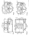
- the cellular wheel sluice comprises, as the main component, a cellular wheel 1, which is rotatably supported with its shaft 2 in the two end faces of a housing drum 3.
- the cellular wheel shaft 2 is driven by a geared motor 5 flanged on a bracket: 4 of the housing drum 3 via a chain drive 6.
- the housing drum 3 comprises a lower cylinder part 7, which is made of non-perforated steel sheet and, viewed in cross section, is somewhat larger than the lower semicircle of the housing drum 3.
- the cylinder part 7 Above the horizontal diameter plane of the housing drum 3, the cylinder part 7 is provided with a circumferential horizontal edge flange 8.
- the cylinder part 7 In the area of the vertical diameter plane of the housing drum 3, the cylinder part 7 is provided with a lower ejection opening 9 in the manner of an ejection shaft extending over the axial length of the housing drum 3.
- an upper perforated sheet jacket 10 is combined with the lower cylinder part 7 in order to form the housing drum 3 together with the latter.
- the perforated sheet jacket 10 essentially occupies the upper half of the circumferential surface of the housing drum 3 and contains a connection opening 11 for connection to a conveyor in the region of the central vertical transverse plane of the housing drum 3 Line for feeding and feeding the air flow containing the solids into the cellular wheel 1.
- the two end faces 12 and 13 of the perforated sheet jacket 10 also consist of perforated sheet which, as in the case of the perforated sheet jacket 10, can be formed from normal steel sheet with a hole diameter of, for example, about 2 mm .
- connection stub 15 From the same perforated sheet there is in its lower area 14 adjoining the perforated sheet casing 10, a separate connecting piece 15 which is attached to the housing-side connection opening 11 and surrounds it firmly connected to the perforated sheet casing 10, e.g. welded, is.
- two line strands of the delivery line for supplying the air / solids flow can be connected to the end of the connection stub 15 opposite the connection opening 11 with the aid of two connection stubs 16.
- the length, measured transversely to the axis of rotation 17 of the cellular wheel 1, of the housing-side connection opening 11 and the region 14 of the connecting piece 15 adjoining it is dimensioned such that in the operating state of the cellular wheel 1 with the connection opening 11 there is always at least two cells 19 formed by the cell walls 18 circumferentially in open connection with the connection opening 11. In a given instantaneous state during the rotation of the Z ellenrades.1 can thereby simultaneously three cells 19 .in.offener connection with the connection opening 11 are, as it. Figure 3 shows. This arrangement is conducive to high air throughput.
- connection opening 11 and the adjoining area 14 of the connecting piece 15 is at most equal to the length of a straight connection between the diametrically opposite base points of the perforated sheet jacket 10, as by the plane of the edge flange 8 is defined.
- the width of the connection opening 11 and the area 1.4 of the connecting piece 15 is expediently about half of that L josenageses. This configuration creates increased perforated surface areas of the connecting piece 15 in its lower connection area 14, which further promotes rapid air passage.
- the perforated sheet jacket 10 is surrounded on the outside at a distance by a cover box 20 which is open at the bottom but is otherwise closed.
- the cover box 20 is placed on the edge flange 8 and firmly connected to it. Together with the perforated sheet jacket 10, the cover box 20 forms a circumferential air guide channel 21 which surrounds the perforated sheet jacket 10 with the perforated area 14 of the connecting piece 15 on all sides and for a rapid removal of the air emerging through the perforated sheet openings to an outlet 22, which in the form of a Stub molded onto the cover box 20 or connected to it in an otherwise suitable manner.
- the perforated plate area 14 of the connecting piece 15 is limited to this air duct 21.
- the upper part 23 of the connecting piece 15 consists of non-perforated sheet metal and is attached to the closed top of the cover box 20 by means of an edge flange.
- FIG. 4 shows an embodiment in which the connecting piece 15 'is aligned laterally via the connection opening 11 r opens into the perforated sheet jacket 10 of the cellular wheel 1.
- the dacasstutzen.15 ' has a short inner or lower to the perforated metal jacket 10 subsequent, die.Anschlußö réelle 11' on the edge side here limiting wall 24 and one of the curvature of the perforated sheet metal casing 10 following the outer wall 25, which andflansches.8 at its end at the level of R to connects the perforated sheet jacket 10 and here limits the connection opening 11 'at the edge.
- the outer wall 25 and the side walls connecting them to the inner wall 24, and possibly also the short inner wall 24 itself consist again of perforated plate analogous to the perforated plate region 14 of the connecting piece 15.
- This arrangement of the connecting piece 15 ' enables a tangential inflow of the air / solid stream via the connection opening 11 r into the perforated sheet jacket 10 or the circumferentially open cells 19, which during the circulation of the Cellular wheel 1 are presented at the connection opening 11 '.
- the tangential inflow of the air flow can prove advantageous for the air throughput under certain operating conditions.
- the outer cover box 20 with the outlet 22 for conveying the air flow surrounds, as in the case of the embodiment according to FIGS. 1 to 3, the perforated sheet jacket 10 and the connecting piece 15 ', with the end of which it closes, and in turn forms the air duct 21 for the rapid removal of the Airflow.
- the cell walls 18 are provided on their radial side edges and their outer edges with sealing and scraper strips 26 made of elastic material, which engage with the inside of the end walls and the inner peripheral surface of the housing drum 3 both in its perforated and in its non-perforated areas are held.
- the solid particles originally contained in the air flow which remain adhering to the inside of the perforated sheet jacket 10 and the perforated end face regions 12, 13 when the air flow is passed through, are stripped off and along the inside of the hole-free cylinder part 7 including its end faces to the ejection opening 9 promoted.
- the cells 19 are sealed against each other by the elastic cell wall strips 26 when they are in contact with the hole-free areas of the housing drum 3, so that the air fed into the cell wheel only emerges from the housing drum 3 via the perforated plate areas of the housing drum 3, including the perforated plate area 14 of the connecting piece 15 and can reach the air outlet 22 via the air guide duct 21.
- the air flow containing the solids is preferably as Compressed air flow supplied to the rotary valve, but this can in principle also be included in a suction air line. It is further understood that instead of the rectangular passage cross-sections shown in the drawing of the housing-side connection opening 11 or the region of the connecting piece 15 adjoining these, other suitable cross-sections, such as polygonal or circular, can be used.
Priority Applications (1)
| Application Number | Priority Date | Filing Date | Title |
|---|---|---|---|
| AT85104640T ATE32693T1 (de) | 1985-02-27 | 1985-04-17 | Zellenradschleuse zum abscheiden feinteiliger feststoffe aus einem luftstrom. |
Applications Claiming Priority (2)
| Application Number | Priority Date | Filing Date | Title |
|---|---|---|---|
| DE19858505540U DE8505540U1 (de) | 1985-02-27 | 1985-02-27 | Zellenradschleuse zum abscheiden feinteiliger feststoffe aus einem luftstrom |
| DE8505540U | 1985-02-27 |
Publications (2)
| Publication Number | Publication Date |
|---|---|
| EP0192803A1 true EP0192803A1 (fr) | 1986-09-03 |
| EP0192803B1 EP0192803B1 (fr) | 1988-03-02 |
Family
ID=6777937
Family Applications (1)
| Application Number | Title | Priority Date | Filing Date |
|---|---|---|---|
| EP85104640A Expired EP0192803B1 (fr) | 1985-02-27 | 1985-04-17 | Sas comprenant une roue à cellules pour séparer de fines particules solides à partir d'un courant d'air |
Country Status (3)
| Country | Link |
|---|---|
| EP (1) | EP0192803B1 (fr) |
| AT (1) | ATE32693T1 (fr) |
| DE (2) | DE8505540U1 (fr) |
Cited By (3)
| Publication number | Priority date | Publication date | Assignee | Title |
|---|---|---|---|---|
| EP0952095A2 (fr) * | 1998-04-22 | 1999-10-27 | Hildegard Thele | Vanne à roue cellulaire |
| DE29821221U1 (de) * | 1998-11-27 | 2000-03-30 | Hoecker Polytechnik | Vorrichtung zum Abscheiden von Feststoffen aus einem Luftstrom |
| DE202008008814U1 (de) | 2008-08-14 | 2009-09-24 | Piepmeyer, Eduard | Vorrichtung zum Abscheiden von Feststoffteilchen aus einem Luftstrom mit einer Zellenradschleuse |
Families Citing this family (1)
| Publication number | Priority date | Publication date | Assignee | Title |
|---|---|---|---|---|
| DE202016003312U1 (de) | 2016-05-24 | 2017-08-31 | Dirk Barnstedt | Vorrichtung zur Abscheidung von Leichtgut aus einem Transportluftstrom |
Citations (4)
| Publication number | Priority date | Publication date | Assignee | Title |
|---|---|---|---|---|
| DE497967C (de) * | 1927-06-22 | 1930-05-16 | United Cigarette Mach Co Inc | Zellenrad zum Ausschleusen des Schuettguts bei pneumatischen Foerderanlagen |
| DE1269948B (de) * | 1966-04-21 | 1968-06-06 | Vokes Ltd | Abgabevorrichtung fuer pneumatisch gefoerdertes Gut |
| DE2338675A1 (de) * | 1973-07-31 | 1975-02-13 | Augsburger Textilmaschf | Abscheider |
| EP0004125A1 (fr) * | 1978-02-04 | 1979-09-19 | Hambro Machinery Limited | Appareil pour séparer de la matière en grains de l'air |
-
1985
- 1985-02-27 DE DE19858505540U patent/DE8505540U1/de not_active Expired
- 1985-04-17 AT AT85104640T patent/ATE32693T1/de not_active IP Right Cessation
- 1985-04-17 EP EP85104640A patent/EP0192803B1/fr not_active Expired
- 1985-04-17 DE DE8585104640T patent/DE3561710D1/de not_active Expired
Patent Citations (4)
| Publication number | Priority date | Publication date | Assignee | Title |
|---|---|---|---|---|
| DE497967C (de) * | 1927-06-22 | 1930-05-16 | United Cigarette Mach Co Inc | Zellenrad zum Ausschleusen des Schuettguts bei pneumatischen Foerderanlagen |
| DE1269948B (de) * | 1966-04-21 | 1968-06-06 | Vokes Ltd | Abgabevorrichtung fuer pneumatisch gefoerdertes Gut |
| DE2338675A1 (de) * | 1973-07-31 | 1975-02-13 | Augsburger Textilmaschf | Abscheider |
| EP0004125A1 (fr) * | 1978-02-04 | 1979-09-19 | Hambro Machinery Limited | Appareil pour séparer de la matière en grains de l'air |
Cited By (7)
| Publication number | Priority date | Publication date | Assignee | Title |
|---|---|---|---|---|
| EP0952095A2 (fr) * | 1998-04-22 | 1999-10-27 | Hildegard Thele | Vanne à roue cellulaire |
| EP0952095A3 (fr) * | 1998-04-22 | 2001-01-17 | Hildegard Thele | Vanne à roue cellulaire |
| DE29821221U1 (de) * | 1998-11-27 | 2000-03-30 | Hoecker Polytechnik | Vorrichtung zum Abscheiden von Feststoffen aus einem Luftstrom |
| EP1004526A2 (fr) * | 1998-11-27 | 2000-05-31 | Höcker Polytechnik GmbH | Dispositif pour séparer des solides d'un courant d'air |
| US6277162B1 (en) * | 1998-11-27 | 2001-08-21 | Hoecker Polytechnik Gmbh | Apparatus for depositing solids from an air current |
| EP1004526A3 (fr) * | 1998-11-27 | 2001-11-28 | Höcker Polytechnik GmbH | Dispositif pour séparer des solides d'un courant d'air |
| DE202008008814U1 (de) | 2008-08-14 | 2009-09-24 | Piepmeyer, Eduard | Vorrichtung zum Abscheiden von Feststoffteilchen aus einem Luftstrom mit einer Zellenradschleuse |
Also Published As
| Publication number | Publication date |
|---|---|
| EP0192803B1 (fr) | 1988-03-02 |
| DE3561710D1 (en) | 1988-04-07 |
| DE8505540U1 (de) | 1985-05-23 |
| ATE32693T1 (de) | 1988-03-15 |
Similar Documents
| Publication | Publication Date | Title |
|---|---|---|
| DE2741710C2 (de) | Vorrichtung zum Trennen von Feststoffen und Flüssigkeiten aus einer Suspension | |
| DE3420157C1 (de) | Vorrichtung zum Entfernen von Rechen- und/oder Siebgut aus in einem Gerinne stroemender Fluessigkeit | |
| DE2647486A1 (de) | Hydrozyklon | |
| DE3590322C2 (de) | Vorrichtung zur Abscheidung von Gas aus einer Fasersuspension | |
| DE2202311C2 (de) | Anlage zur Wiedergewinnung von Sand aus dem beim Abstrahlen von kunstharzgebundenen Formen anfallenden Gemisch | |
| DE2744522A1 (de) | Verfahren und vorrichtung zum kontinuierlichen mischen von holzspaenen mit bindemittel | |
| DE2027028A1 (de) | Siebmaschine für Fasersuspensionen | |
| DE2150800A1 (de) | Vorrichtung zum Sieben von Saatgut u.dgl. | |
| DE3322578A1 (de) | Sortiervorrichtung | |
| EP0261241B1 (fr) | Desintegrateur | |
| DE2901720C2 (de) | Zellenrad-Luftschleuse | |
| EP0192803B1 (fr) | Sas comprenant une roue à cellules pour séparer de fines particules solides à partir d'un courant d'air | |
| DE19900280A1 (de) | Fluid-Trennvorrichtung | |
| DE2908729C2 (fr) | ||
| DE60021567T2 (de) | Schleuse zum entladen von schüttgut | |
| DE3210385C2 (de) | Sortiertrommel | |
| DE3726610A1 (de) | Mahlkoerperabtrennsystem in ruehrwerkskugelmuehlen | |
| DE19818270A1 (de) | Verbesserungen betreffend Tabakseparatoren bzw. Tabaktrennvorrichtungen | |
| DE1279538B (de) | Zentrifugalabscheider | |
| DE3626044C2 (fr) | ||
| DE2750499B2 (de) | Sortierer für Fasersuspension | |
| DE3612103C2 (fr) | ||
| WO2005080238A1 (fr) | Separateur tangentiel servant a separer le tabac contenu dans un courant air-tabac | |
| DE3318797C2 (de) | Zellenradschleuse | |
| DE2245580C2 (de) | Kreiselbrecher mit im Gutaufgabebereich angeordneter Gutverteilvorrichtung |
Legal Events
| Date | Code | Title | Description |
|---|---|---|---|
| PUAI | Public reference made under article 153(3) epc to a published international application that has entered the european phase |
Free format text: ORIGINAL CODE: 0009012 |
|
| AK | Designated contracting states |
Kind code of ref document: A1 Designated state(s): AT CH DE LI |
|
| 17P | Request for examination filed |
Effective date: 19861103 |
|
| 17Q | First examination report despatched |
Effective date: 19870811 |
|
| GRAA | (expected) grant |
Free format text: ORIGINAL CODE: 0009210 |
|
| AK | Designated contracting states |
Kind code of ref document: B1 Designated state(s): AT CH DE LI |
|
| REF | Corresponds to: |
Ref document number: 32693 Country of ref document: AT Date of ref document: 19880315 Kind code of ref document: T |
|
| REF | Corresponds to: |
Ref document number: 3561710 Country of ref document: DE Date of ref document: 19880407 |
|
| PLBE | No opposition filed within time limit |
Free format text: ORIGINAL CODE: 0009261 |
|
| STAA | Information on the status of an ep patent application or granted ep patent |
Free format text: STATUS: NO OPPOSITION FILED WITHIN TIME LIMIT |
|
| 26N | No opposition filed | ||
| PGFP | Annual fee paid to national office [announced via postgrant information from national office to epo] |
Ref country code: DE Payment date: 20040202 Year of fee payment: 20 |
|
| PGFP | Annual fee paid to national office [announced via postgrant information from national office to epo] |
Ref country code: CH Payment date: 20040413 Year of fee payment: 20 |
|
| PGFP | Annual fee paid to national office [announced via postgrant information from national office to epo] |
Ref country code: AT Payment date: 20040426 Year of fee payment: 20 |
|
| REG | Reference to a national code |
Ref country code: CH Ref legal event code: PL |