EP0192803A1 - Cock comprising a cellular wheel for separating fine solid particles from an air stream - Google Patents
Cock comprising a cellular wheel for separating fine solid particles from an air stream Download PDFInfo
- Publication number
- EP0192803A1 EP0192803A1 EP85104640A EP85104640A EP0192803A1 EP 0192803 A1 EP0192803 A1 EP 0192803A1 EP 85104640 A EP85104640 A EP 85104640A EP 85104640 A EP85104640 A EP 85104640A EP 0192803 A1 EP0192803 A1 EP 0192803A1
- Authority
- EP
- European Patent Office
- Prior art keywords
- connection opening
- air
- housing
- perforated sheet
- rotary valve
- Prior art date
- Legal status (The legal status is an assumption and is not a legal conclusion. Google has not performed a legal analysis and makes no representation as to the accuracy of the status listed.)
- Granted
Links
Images
Classifications
-
- B—PERFORMING OPERATIONS; TRANSPORTING
- B65—CONVEYING; PACKING; STORING; HANDLING THIN OR FILAMENTARY MATERIAL
- B65G—TRANSPORT OR STORAGE DEVICES, e.g. CONVEYORS FOR LOADING OR TIPPING, SHOP CONVEYOR SYSTEMS OR PNEUMATIC TUBE CONVEYORS
- B65G53/00—Conveying materials in bulk through troughs, pipes or tubes by floating the materials or by flow of gas, liquid or foam
- B65G53/34—Details
- B65G53/60—Devices for separating the materials from propellant gas
Definitions
- the invention relates to a rotary valve for separating finely divided solids from an air stream, consisting of a cellular wheel rotatably supported for circulation in a housing drum, a connection opening in the housing drum for a connection to a delivery line for supplying and feeding the air stream containing the solids into the cells of the Cell wheel, an outlet connected to the connection opening via a sieve for conveying the air flow and with an ejection opening for solid particles separated from the air flow by means of the sieve.
- the outlet for conveying the air flow and the screen are directly associated with the feeder itself so that the separation of F örder- air and particulates, as well as the discharge of the conveyor air on the one hand and the discharging of the solid particles on the other hand directly on the cells or the cell walls of the cellular wheel.
- the cells of the cell wheel are divided into outer cell pockets and inner cell chambers connected to the outlet for conveying the air flow, which are each pneumatically connected to one another by sieves between the cells.
- the invention has for its object to provide a rotary valve of the type specified, which is capable of absorbing large volumes of air per unit of time and effectively separating solid particles distributed therein from the air stream without any significant increase in size.
- the sieve is formed by a perforated sheet metal jacket, which substantially occupies half of its circumferential surface on the side of the housing drum adjacent to the housing-side connection opening, and in that the perforated sheet metal jacket is surrounded on the outside at a distance from a cover box , which, with the perforated sheet jacket, forms a circumferential air duct for the air that has passed through the perforated sheet jacket, opening into the outlet for conveying the air flow.
- the air passage surfaces can be further enlarged in a further embodiment of the invention in that the two end faces of the housing drum in their surface areas corresponding to the circumferential length of the perforated sheet jacket as well as a separate connecting piece attached to the housing-side connection opening in the area of the circumferential air duct of their consist of perforated sheet.
- the cell walls are inventively designed Z ellenradschleuse preferably at their radial lateral edges and their outer edges provided with sealing and scraper strips of elastic material, the mit.den inner sides of the end walls and the inner circumferential surface are held to the housing drum in engagement.
- the individual cells of the cellular wheel are each sealed off from one another, so that, in the interest of a high level of operational safety and a high material separation performance, the air quantities fed in through the housing-side connection opening are forced to leave the cellular wheel sluice only via the perforated sheet metal components of the housing drum through the outlet for conveying the air flow.
- the solid particles originally contained in the air flow such as in paper processing from punching, trimming and.
- the rotary valve shown in the drawing for the A-b separate finely divided solids from a stream of air may find particular application in the papierver inden.Industrie, wherein small paper wastes and from the punching, trimming. Like processing operations originate, are to be separated. Large air capacities are used for the removal from the processing machines, so that the cellular wheel sluice has to pass large amounts of air per unit of time with effective separation of the solids.
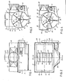
- the cellular wheel sluice comprises, as the main component, a cellular wheel 1, which is rotatably supported with its shaft 2 in the two end faces of a housing drum 3.
- the cellular wheel shaft 2 is driven by a geared motor 5 flanged on a bracket: 4 of the housing drum 3 via a chain drive 6.
- the housing drum 3 comprises a lower cylinder part 7, which is made of non-perforated steel sheet and, viewed in cross section, is somewhat larger than the lower semicircle of the housing drum 3.
- the cylinder part 7 Above the horizontal diameter plane of the housing drum 3, the cylinder part 7 is provided with a circumferential horizontal edge flange 8.
- the cylinder part 7 In the area of the vertical diameter plane of the housing drum 3, the cylinder part 7 is provided with a lower ejection opening 9 in the manner of an ejection shaft extending over the axial length of the housing drum 3.
- an upper perforated sheet jacket 10 is combined with the lower cylinder part 7 in order to form the housing drum 3 together with the latter.
- the perforated sheet jacket 10 essentially occupies the upper half of the circumferential surface of the housing drum 3 and contains a connection opening 11 for connection to a conveyor in the region of the central vertical transverse plane of the housing drum 3 Line for feeding and feeding the air flow containing the solids into the cellular wheel 1.
- the two end faces 12 and 13 of the perforated sheet jacket 10 also consist of perforated sheet which, as in the case of the perforated sheet jacket 10, can be formed from normal steel sheet with a hole diameter of, for example, about 2 mm .
- connection stub 15 From the same perforated sheet there is in its lower area 14 adjoining the perforated sheet casing 10, a separate connecting piece 15 which is attached to the housing-side connection opening 11 and surrounds it firmly connected to the perforated sheet casing 10, e.g. welded, is.
- two line strands of the delivery line for supplying the air / solids flow can be connected to the end of the connection stub 15 opposite the connection opening 11 with the aid of two connection stubs 16.
- the length, measured transversely to the axis of rotation 17 of the cellular wheel 1, of the housing-side connection opening 11 and the region 14 of the connecting piece 15 adjoining it is dimensioned such that in the operating state of the cellular wheel 1 with the connection opening 11 there is always at least two cells 19 formed by the cell walls 18 circumferentially in open connection with the connection opening 11. In a given instantaneous state during the rotation of the Z ellenrades.1 can thereby simultaneously three cells 19 .in.offener connection with the connection opening 11 are, as it. Figure 3 shows. This arrangement is conducive to high air throughput.
- connection opening 11 and the adjoining area 14 of the connecting piece 15 is at most equal to the length of a straight connection between the diametrically opposite base points of the perforated sheet jacket 10, as by the plane of the edge flange 8 is defined.
- the width of the connection opening 11 and the area 1.4 of the connecting piece 15 is expediently about half of that L josenageses. This configuration creates increased perforated surface areas of the connecting piece 15 in its lower connection area 14, which further promotes rapid air passage.
- the perforated sheet jacket 10 is surrounded on the outside at a distance by a cover box 20 which is open at the bottom but is otherwise closed.
- the cover box 20 is placed on the edge flange 8 and firmly connected to it. Together with the perforated sheet jacket 10, the cover box 20 forms a circumferential air guide channel 21 which surrounds the perforated sheet jacket 10 with the perforated area 14 of the connecting piece 15 on all sides and for a rapid removal of the air emerging through the perforated sheet openings to an outlet 22, which in the form of a Stub molded onto the cover box 20 or connected to it in an otherwise suitable manner.
- the perforated plate area 14 of the connecting piece 15 is limited to this air duct 21.
- the upper part 23 of the connecting piece 15 consists of non-perforated sheet metal and is attached to the closed top of the cover box 20 by means of an edge flange.
- FIG. 4 shows an embodiment in which the connecting piece 15 'is aligned laterally via the connection opening 11 r opens into the perforated sheet jacket 10 of the cellular wheel 1.
- the dacasstutzen.15 ' has a short inner or lower to the perforated metal jacket 10 subsequent, die.Anschlußö réelle 11' on the edge side here limiting wall 24 and one of the curvature of the perforated sheet metal casing 10 following the outer wall 25, which andflansches.8 at its end at the level of R to connects the perforated sheet jacket 10 and here limits the connection opening 11 'at the edge.
- the outer wall 25 and the side walls connecting them to the inner wall 24, and possibly also the short inner wall 24 itself consist again of perforated plate analogous to the perforated plate region 14 of the connecting piece 15.
- This arrangement of the connecting piece 15 ' enables a tangential inflow of the air / solid stream via the connection opening 11 r into the perforated sheet jacket 10 or the circumferentially open cells 19, which during the circulation of the Cellular wheel 1 are presented at the connection opening 11 '.
- the tangential inflow of the air flow can prove advantageous for the air throughput under certain operating conditions.
- the outer cover box 20 with the outlet 22 for conveying the air flow surrounds, as in the case of the embodiment according to FIGS. 1 to 3, the perforated sheet jacket 10 and the connecting piece 15 ', with the end of which it closes, and in turn forms the air duct 21 for the rapid removal of the Airflow.
- the cell walls 18 are provided on their radial side edges and their outer edges with sealing and scraper strips 26 made of elastic material, which engage with the inside of the end walls and the inner peripheral surface of the housing drum 3 both in its perforated and in its non-perforated areas are held.
- the solid particles originally contained in the air flow which remain adhering to the inside of the perforated sheet jacket 10 and the perforated end face regions 12, 13 when the air flow is passed through, are stripped off and along the inside of the hole-free cylinder part 7 including its end faces to the ejection opening 9 promoted.
- the cells 19 are sealed against each other by the elastic cell wall strips 26 when they are in contact with the hole-free areas of the housing drum 3, so that the air fed into the cell wheel only emerges from the housing drum 3 via the perforated plate areas of the housing drum 3, including the perforated plate area 14 of the connecting piece 15 and can reach the air outlet 22 via the air guide duct 21.
- the air flow containing the solids is preferably as Compressed air flow supplied to the rotary valve, but this can in principle also be included in a suction air line. It is further understood that instead of the rectangular passage cross-sections shown in the drawing of the housing-side connection opening 11 or the region of the connecting piece 15 adjoining these, other suitable cross-sections, such as polygonal or circular, can be used.
Abstract
Description
Die Erfindung betrifft eine Zellenradschleuse zum Abscheiden feinteiliger Feststoffe aus einem Luftstrom, bestehend aus einem für einen Umlauf in einer Gehäusetrommel drehbar abgestützten Zellenrad, einer Anschlußöffnung in der Gehäusetrommel für eine Verbindung mit einer Förderleitung zum Zuführen und Einspeisen des die Feststoffe enthaltenden Luftstroms in die Zellen des Zellenrades, einem über ein Sieb mit der Anschlußöffnung in Verbindung stehenden Auslaß zum Abfördern des Luftstroms und mit einer Auswurföffnung für mittels des Siebes aus dem Luftstrom abgeschiedene Feststoffteilchen.The invention relates to a rotary valve for separating finely divided solids from an air stream, consisting of a cellular wheel rotatably supported for circulation in a housing drum, a connection opening in the housing drum for a connection to a delivery line for supplying and feeding the air stream containing the solids into the cells of the Cell wheel, an outlet connected to the connection opening via a sieve for conveying the air flow and with an ejection opening for solid particles separated from the air flow by means of the sieve.
Bei einer bekannten Zellenradschleuse dieser Art sind der Auslaß zum Abfördern des Luftstroms und das Sieb unmittelbar dem Zellenrad selbst zugeordnet, derart, daß die Trennung von Förder- luft und Feststoffteilchen sowie das Abführen der Förderluft einerseits und das Ausschleusen der Feststoffteilchen andererseits direkt über die Zellen bzw. die Zellenwände des Zellenrades erfolgt. Zu diesem Zweck sind die Zellen des Zellenrades in äußere Zellentaschen und innere, an den Auslaß zum Abfördern des Luftstroms angeschlossene Zellenkammern unterteilt, die jeweils durch Siebe zwischen den Zellen pneumatisch miteinander in Verbindung stehen. Durch.diese Ausgestaltung ist zwar eine kompakte Bauweise der Zellenradschleuse erreicht, jedoch sind derartige Zellenradschleusen mit in die Zellenwände integrierten Trennsieben nicht für einen Betrieb mit hohen Luftdurchsätzen geeignet, um in feiner Verteilung im Luftstrom enthaltene leichte Feststoffteilchen, wie Papierabfälle,wirksam aus dem Luftstrom abzuscheiden. Dies ist vor allen Dingen dadurch bedingt, daß die im Inneren des Zellenrades angeordneten Trennsiebe der bekannten Zellenradschleuse nur begrenzte Durchtrittsflächen für die in das Zellenrad eingespeisten Luftvolumen darbieten.In a known rotary valve of this type, the outlet for conveying the air flow and the screen are directly associated with the feeder itself so that the separation of F örder- air and particulates, as well as the discharge of the conveyor air on the one hand and the discharging of the solid particles on the other hand directly on the cells or the cell walls of the cellular wheel. For this purpose, the cells of the cell wheel are divided into outer cell pockets and inner cell chambers connected to the outlet for conveying the air flow, which are each pneumatically connected to one another by sieves between the cells. Although this design achieves a compact design of the cellular wheel sluice, such cellular wheel sluices with separating screens integrated into the cell walls are not suitable for operation with high air throughputs Suitable for effectively separating light solid particles, such as paper waste, contained in the air stream from the air stream. This is primarily due to the fact that the separating screens arranged in the interior of the cellular wheel of the known cellular wheel sluice provide only limited passage areas for the air volumes fed into the cellular wheel.
Der Erfindung liegt die Aufgabe zugrunde, eine Zellenradschleuse der eingangs angegebenen Art zu schaffen, die ohne nennenswerte Erhöhung ihrer Baugröße in der Lage ist, große Luftvolumen pro Zeiteinheit aufzunehmen und in diesen verteilte Feststoffpartikel wirksam aus dem Luftstrom abzuscheiden.The invention has for its object to provide a rotary valve of the type specified, which is capable of absorbing large volumes of air per unit of time and effectively separating solid particles distributed therein from the air stream without any significant increase in size.
Diese Aufgabe wird nach der Erfindung dadurch gelöst, daß das Sieb von einem Lochblechmantel gebildet ist, der die an die gehäuseseitige Anschlußöffnung angrenzende Seite der Gehäusetrommel im wesentlichen zur Hälfte ihrer Umfangsfläche einnimmt, und daß der Lochblechmantel,außen mit Abstand von einem Abdeckkasten.umgeben ist, der mit dem Lochblechmantel einen umlaufenden, in den Auslaß zum Abfördern des.Luftströms einmündenden Luftleitkanal für die durch den Lochblechmantel hindurchgetretene Luft bildet. Bei dieser Ausgestaltung können dadurch, daß praktisch die Hälfte der Umfangsfläche der Gehäusetrommel durch.den vorgesehenen Lochblechmantel als Siebfläche ausgebildet ist, große Luftvolumen in Verbindung mit dem durch den äußeren Abdeckkasten gebildeten umlaufenden Luftleitkanal unter gleichzeitiger wirksamer Ausscheidung der im Luftstrom enthaltenen.Feststoffteilchen durchgeschleust werden, ohne daß es zu Blockierungen kommtbund die Baugröße wesentlich erhöht ist.This object is achieved according to the invention in that the sieve is formed by a perforated sheet metal jacket, which substantially occupies half of its circumferential surface on the side of the housing drum adjacent to the housing-side connection opening, and in that the perforated sheet metal jacket is surrounded on the outside at a distance from a cover box , which, with the perforated sheet jacket, forms a circumferential air duct for the air that has passed through the perforated sheet jacket, opening into the outlet for conveying the air flow. With this configuration, because practically half of the circumferential surface of the housing drum is designed as a sieve surface through the perforated sheet jacket provided, large volumes of air can be passed through in connection with the circumferential air duct formed by the outer cover box with simultaneous effective separation of the solid particles contained in the air stream. without blocking and the size is significantly increased.
Die Luftdurchtrittsflächen können in weiterer Ausgestaltung der Erfindung dadurch noch vergrößert werden, daß auch die beiden Stirnseiten der Gehäusetrommel in ihren der Umfangslänge des Lochblechmantels entsprechenden Flächenbereichen sowie ein an die gehäuseseitige Anschlußöffnung angesetzter gesonderter Verbindungsstutzen im Bereich des umlaufenden Luftleitkanals ihrerseits aus Lochblech bestehen.The air passage surfaces can be further enlarged in a further embodiment of the invention in that the two end faces of the housing drum in their surface areas corresponding to the circumferential length of the perforated sheet jacket as well as a separate connecting piece attached to the housing-side connection opening in the area of the circumferential air duct of their consist of perforated sheet.
Die Zellenwände sind in der erfindungsgemäß ausgestalteten Zellenradschleuse vorzugsweise an ihren radialen Seitenrändern und ihren Außenrändern mit Dichtungs- und Abstreifleisten aus elastischem Werkstoff versehen, die mit.den Innenseitender Stirnwände und der inneren Umfangsfläche der Gehäusetrommel in Eingriff gehalten sind. Hierdurch sind die einzelnen Zellen des Zellenrades jeweils gegeneinander abgedichtet, so daß im Interesse einer großen Betriebssicherheit und einer hohen Materialabscheidungsleistung die durch die gehäuseseitige Anschlußöffnung eingespeisten Luftmengen gezwungen sind, lediglich über die Lochblechbestandteile der Gehäusetrommel durch den Auslaß zum Abfördern des Luftströms die Zellenradschleuse zu verlassen. Die im Luftstrom ursprünglich enthaltenen Feststoffteilchen, wie bei der Papierverarbeitung vom Stanzen, Besäumen u. dgl. herrührende Papierabfälle, die dabei an der Innenseite des Lochblechmantels und der gelochten Stirnseitenbereiche der Gehäusetrommel haften bleiben, werden beim Umlauf des Zellenrades von den elastischen Zellenwandleisten zugleich sicher abgestreift und entlang der Innenseite des lochfreien Gehäusetrommelbereichs zur Auswurföffnung gefördert.The cell walls are inventively designed Z ellenradschleuse preferably at their radial lateral edges and their outer edges provided with sealing and scraper strips of elastic material, the mit.den inner sides of the end walls and the inner circumferential surface are held to the housing drum in engagement. As a result, the individual cells of the cellular wheel are each sealed off from one another, so that, in the interest of a high level of operational safety and a high material separation performance, the air quantities fed in through the housing-side connection opening are forced to leave the cellular wheel sluice only via the perforated sheet metal components of the housing drum through the outlet for conveying the air flow. The solid particles originally contained in the air flow, such as in paper processing from punching, trimming and. Similar paper waste that adheres to the inside of the perforated sheet jacket and the perforated end face areas of the housing drum is at the same time safely stripped off by the elastic cell wall strips when the cell wheel rotates and conveyed along the inside of the hole-free housing drum area to the ejection opening.
Weitere Merkmale und Vorteile der Erfindung ergeben sich aus den Ansprüchen und der nachstehenden Beschreibung in Verbindung mit der Zeichnung, in der..zwei Ausführungsbeispiele des Gegenstands der Erfindung schematisch veranschaulicht sind. In der Zeichnung...zeigen:
- Fig. 1 eine Seitenansicht einer erfindungsgemäßen Zellen- radschleuse zum Abscheiden feinteiliger Feststoffe, wie Papierabfälle, aus einem Luftstrom,
- Fig..2 : eine teilweise geschnitte Draufsicht auf die Zellenradschleuse nach Fig. 1,
- Fig. 3 einen Schnitt nach der Linie III-III der Fig. 2 .und
- Fig. 4 eine Darstellung entsprechend Fig. 3 zur Veranschaulichung einer abgewandelten Ausführungsform.
- 1 shows a side view of a cellular wheel sluice according to the invention for separating finely divided solids, such as paper waste, from an air stream,
- Fig. 2: a partially sectioned plan view of the rotary valve according to Fig. 1,
- Fig. 3 is a section along the line III-III of Fig. 2. And
- Fig. 4 is an illustration corresponding to Fig. 3 for Veran clarification of a modified embodiment.
Die in der Zeichnung dargestellte Zellenradschleuse zum Ab-scheiden feinteiliger Feststoffe aus einem Luftstrom kann insbesondere in der papierverarbeitenden.Industrie Anwendung finden, wobei kleine Papierabfälle, die vom Stanzen, Besäumen u. dgl. Bearbeitungsvorgängen herrühren, abzuscheiden sind. Für die Abförderung von den Verarbeitungsmaschinen werden dabei große Luftleistungen eingesetzt, so daß die,Zellenradschleuse entsprechend große Luftmengen pro Zeiteinheit unter wirksamer Abscheidung der Feststoffe durchschleusen muß.The rotary valve shown in the drawing for the A-b separate finely divided solids from a stream of air may find particular application in the papierverarbeitenden.Industrie, wherein small paper wastes and from the punching, trimming. Like processing operations originate, are to be separated. Large air capacities are used for the removal from the processing machines, so that the cellular wheel sluice has to pass large amounts of air per unit of time with effective separation of the solids.
Die Zellenradschleuse umfaßt, wie an sich bekannt, als Hauptbestandteil ein Zellenrad 1, das mit seiner Welle 2 in den beiden Stirnseiten einer Gehäusetrommel 3 drehbar abgestützt ist. Der Antrieb der Zellenradwelle 2 erfolgt von einem auf einer Konsole :4 der Gehäusetrommel 3 angeflanschten Getriebemotor 5 über einen Kettentrieb 6.As known per se, the cellular wheel sluice comprises, as the main component, a cellular wheel 1, which is rotatably supported with its
Die Gehäusetrommel 3 umfaßt einen unteren Zylinderteil 7, der aus ungelochtem Stahlblech besteht und im Querschnitt gesehen etwas größer ist als der untere Halbkreis der Gehäusetrommel 3. Oberhalb der waagerechten Durchmesserebene der Gehäusetrommel 3 ist der Zylinderteil 7 mit einem umlaufenden waagerechten Randflansch 8 versehen. Im Bereich der senkrechten Durchmesserebene der Gehäusetrommel.3 ist der Zylinderteil 7 mit einer unteren Auswurföffnung 9 nach Art eines sich über die axiale Länge der Gehäusetrommel 3 erstreckenden Auswurfschachtes versehen.The
Im Bereich des waagerechten Randflansches 8 ist ein oberer Lochblechmantel 10.mit dem unteren Zylinderteil 7 vereinigt, um gemeinsam mit diesem die Gehäusetrommel 3 zu bilden. Der Lochblechmantel 10 nimmt dabei im wesentlichen die obere Hälfte der Umfangsfläche der Gehäusetrommel 3 ein und enthält im Bereich der mittleren senkrechten Querebene der Gehäusetrommel 3 eine AnschluBöffnung 11 für eine Verbindung mit einer Förderleitung zum Zuführen und Einspeisen des die Feststoffe enthaltenden Luftstroms in das Zellenrad 1. Die beiden Stirnseiten 12 und 13 des Lochblechmantels 10 bestehen ebenfalls aus Lochblech, das wie im Falle des Lochblechmantels 10 von normalem Stahlblech mit einem Lochdurchmesser von beispielsweise etwa 2 mm gebildet sein kann.In the area of the
Aus dem gleichen Lochblech besteht in seinem an den Lochblechmantel 10 angrenzenden unteren Bereich 14 ein gesonderter Verbindungsstutzen 15, der an die gehäuseseitige Anschlußöffnung 11 angesetzt und diese umgebend mit dem Lochblechmantel 10 fest verbunden,.z.B. verschweißt, ist. An das der Anschlußöffnung 11 gegenüber.liegende Ende des Verbindungsstutzens 15 sind bei dem dargestellten Beispiel zwei Leitungsstränge der Förderleitung für die Zuführung des Luft/Feststoff-Stroms mit Hilfe zweier Anschlußstutzen 16 anschließbar.From the same perforated sheet there is in its
Die quer zur.Drehachse 17 des Zellenrades 1 gemessene Länge der gehäuseseitigen_Anschlußöffnung 11 und des an diese angrenzenden Bereichs 14 des Verbindungsstutzens 15 ist so bemessen, daß im Betriebszustand des Zellenrades 1 mit der Anschlußöffnung 11 stets zumindest zwei von den Zellenwänden 18 gebildete Zellen 19 umfangsseitig in offener Verbindung mit der.Anschlußöffnung 11 stehen. In einem gegebenen Momentanzustand während des Umlaufs des Zellenrades.1 können dabei auch gleichzeitig drei Zellen 19 .in.offener Verbindung mit der Anschlußöffnung 11 stehen, wie es Fig. 3 zeigt. Diese Anordnung ist einem hohen Luftdurchsatz förderlich.The length, measured transversely to the axis of
Die in der Ebene gemessene Länge der Anschlußöffnung 11 und des andiese angrenzenden Bereichs 14 des Verbindungsstutzens 15, wie sie in Fig. 2 zur Darstellung kommt, ist höchstens gleich der Länge einer geraden Verbindung zwischen den einander diametral gegenüberliegenden Fußpunkten des Lochblechmantels 10, wie sie durch die Ebene des Randflansches 8 definiert ist. Die Breite der Anschlußöffnung 11 und des. Bereichs 1.4 des Verbindungsstutzens 15 beträgt dabei zweckmäßig etwa die Hälfte ihres Längenmaßes. Diese Ausgestaltung schafft vermehrte Lochflächenbereiche des Verbindungsstutzens 15 in seinem unteren Anschlußbereich 14, was eine rasche Luftdurchschleusung weiter begünstigt.The measured in the plane length of the connection opening 11 and the
Der Lochblechmantel 10 ist außen mit Abstand von einem nach unten offenen, im übrigen aber geschlossenen Abdeckkasten 20 umgeben. Der Abdeckkasten 20 ist auf den Randflansch 8 aufgesetzt und mit diesem fest verbunden. Zusammen mit dem Lochblechmantel 10 bildet der Abdeckkasten 20 einen umlaufenden Luftleitkanal 21, der den Lochblechmantel 10 mit dem gelochten Bereich 14 des Verbindungsstutzens 15 allseits umgibt und für eine rasche Abförderung der durch die Lochblechöffnungen austretenden Luft zu einem Auslaß 22 Sorge trägt, der in Form eines Stutzens an den Abdeckkasten 20 angeformt oder mit diesem in sonst geeigneter Weise verbunden ist.The perforated
Auf diesen Luftleitkanal 21 ist der Lochblechbereich 14 des Verbindungsstutzens 15 beschränkt. Der obere Teil 23 des Verbindungsstutzens 15 besteht aus ungelochtem Blech und ist an der geschlossenen Oberseite des Abdeckkastens 20 mittels eines Randflansches befestigt.The
Während bei dem Ausführungsbeispiel nach den Fig. 1 bis 3 der Verbindüngsstutzen 15 senkrecht von oben über die gehäuseseitige Anschlußöffnung 11 in den Lochblechmantel 10 des Zellenrades 1 einmündet, zeigt Fig. 4 eine Ausgestaltung, bei der der Verbindungsstutzen 15' in seitlicher Ausrichtung über die Anschlußöffnung 11r in den Lochblechmantel 10 des Zellenrades 1 einmündet. Der Verbindungsstutzen.15' hat eine kurze innere oder untere an den Lochblechmantel 10 anschließende, die.Anschlußöffnung 11' hier randseitig begrenzende Wand 24 und eine der Krümmung des Lochblechmantels 10 folgende Außenwand 25, die an ihrem Ende in Höhe des Randflansches.8 an den Lochblechmantel 10 anschließt und hier die Anschlußöffnung 11' randseitig begrenzt. Die Außenwand 25 und die diese mit der Innenwand 24 verbindenden Seitenwände sowie ggf auch die kurze Innenwand 24 selbst bestehen wiederum aus Lochblech analog dem Lochblechbereich 14 des Verbindungsstutzens 15. Diese Anordnung des Verbindungsstutzens 15' ermöglicht eine tangentiale Einströmung des Luft/Feststoff-Stroms über die Anschlußöffnung 11r in den Lochblechmantel 10 bzw. die umfangsseitig offenen Zellen 19, die beim Umlauf des Zellenrades 1 an der Anschlußöffnung 11' jeweils dargeboten werden. Die tangentiale Einströmung des Luftstroms kann sich unter bestimmten Betriebsbedingungen als vorteilhaft für den Luftdurchsatz erweisen. Der äußere Abdeckkasten 20 mit dem Auslaß 22 zum Abfördern des Luftstroms umgibt wie im Falle des Ausführungsbeispiels nach den Fig. 1 bis 3 den Lochblechmantel 10 sowie den Verbindungsstutzen 15', mit dessen Stirnseite er abschließt, und bildet wiederum den Luftleitkanal 21 zur raschen Abförderung des Luftstroms aus.While in the exemplary embodiment according to FIGS. 1 to 3 the connecting
Bei beiden Ausführungsbeispielen sind die Zellenwände 18 an ihren radialen Seitenrändern und ihren Außenrändern mit Dichtungs- und Abstreifleisten 26 aus elastischem Werkstoff versehen, die mit den Innenseiten der Stirnwände und der inneren Umfangsfläche der Gehäusetrommel 3 sowohl in deren gelochten als auch in deren ungelochten Bereichen in Eingriff gehalten sind. Hierdurch werden im Betrieb der Zellenradschleuse die ursprünglich im Luftstrom enthaltenen Feststoffteilchen, die beim Durchschleusen des Luftstroms an der Innenseite des Lochblechmantels 10 und der gelochten Stirnseitenbereiche 12,13 haften bleiben, abgestreift und entlang der Innenseite des lochfreien Zylinderteils 7 einschließlich dessen.Stirnseiten zur Auswurföffnung 9 gefördert. Zugleich werden die Zellen 19 durch die elastischen.Zellenwandleisten 26 gegeneinander bei Anlage an den lochfreien Bereichen der Gehäusetrommel 3 abgedichtet, so daß die in das Zellenrad eingespeiste Luft nur über die Lochblechbereiche der Gehäusetrommel 3 einschließlich des Lochblechbereichs 14 des Verbindungsstutzens 15 aus der Gehäusetrommel 3 austreten und über den Luftleitkanal.21 zum Luftauslaß 22 gelangen kann.In both embodiments, the
Der die Feststoffe enthaltende Luftstrom wird vorzugsweise als Druckluftstrom der Zellenradschleuse zugeführt, jedoch kann diese grundsätzlich auch in eine Saugluftleitung einbezogen sein. Es versteht sich ferner, daß anstelle der in der Zeichnung dargestellten rechteckigen Durchtrittsquerschnitte der gehäuseseitigen Anschlußöffnung 11 bzw. des an diese angrenzenden Bereichs des Verbindungsstutzens 15 andere geeignete Querschnitte,wie polygonale oder kreisförmige, Anwendung finden können.The air flow containing the solids is preferably as Compressed air flow supplied to the rotary valve, but this can in principle also be included in a suction air line. It is further understood that instead of the rectangular passage cross-sections shown in the drawing of the housing-side connection opening 11 or the region of the connecting
Claims (11)
Priority Applications (1)
| Application Number | Priority Date | Filing Date | Title |
|---|---|---|---|
| AT85104640T ATE32693T1 (en) | 1985-02-27 | 1985-04-17 | ROTARY WHEEL LOCK FOR SEPARATING FINE PARTICULATED SOLIDS FROM AN AIR FLOW. |
Applications Claiming Priority (2)
| Application Number | Priority Date | Filing Date | Title |
|---|---|---|---|
| DE19858505540U DE8505540U1 (en) | 1985-02-27 | 1985-02-27 | CELLWHEEL LOCK FOR SEPARATING FINE-PARTICLE SOLIDS FROM AN AIRFLOW |
| DE8505540U | 1985-02-27 |
Publications (2)
| Publication Number | Publication Date |
|---|---|
| EP0192803A1 true EP0192803A1 (en) | 1986-09-03 |
| EP0192803B1 EP0192803B1 (en) | 1988-03-02 |
Family
ID=6777937
Family Applications (1)
| Application Number | Title | Priority Date | Filing Date |
|---|---|---|---|
| EP85104640A Expired EP0192803B1 (en) | 1985-02-27 | 1985-04-17 | Cock comprising a cellular wheel for separating fine solid particles from an air stream |
Country Status (3)
| Country | Link |
|---|---|
| EP (1) | EP0192803B1 (en) |
| AT (1) | ATE32693T1 (en) |
| DE (2) | DE8505540U1 (en) |
Cited By (3)
| Publication number | Priority date | Publication date | Assignee | Title |
|---|---|---|---|---|
| EP0952095A2 (en) * | 1998-04-22 | 1999-10-27 | Hildegard Thele | Rotary valve apparatus |
| DE29821221U1 (en) * | 1998-11-27 | 2000-03-30 | Hoecker Polytechnik | Device for separating solids from an air stream |
| DE202008008814U1 (en) | 2008-08-14 | 2009-09-24 | Piepmeyer, Eduard | Device for separating solid particles from an air stream with a rotary valve |
Families Citing this family (1)
| Publication number | Priority date | Publication date | Assignee | Title |
|---|---|---|---|---|
| DE202016003312U1 (en) | 2016-05-24 | 2017-08-31 | Dirk Barnstedt | Device for separating light goods from a transport air stream |
Citations (4)
| Publication number | Priority date | Publication date | Assignee | Title |
|---|---|---|---|---|
| DE497967C (en) * | 1927-06-22 | 1930-05-16 | United Cigarette Mach Co Inc | Cell wheel for discharging the bulk material in pneumatic conveyor systems |
| DE1269948B (en) * | 1966-04-21 | 1968-06-06 | Vokes Ltd | Dispensing device for pneumatically conveyed goods |
| DE2338675A1 (en) * | 1973-07-31 | 1975-02-13 | Augsburger Textilmaschf | Separator for textile waste extractor - has counter rotating sieve drum with elastic air seal flaps |
| EP0004125A1 (en) * | 1978-02-04 | 1979-09-19 | Hambro Machinery Limited | Apparatus for separating airborne matter |
-
1985
- 1985-02-27 DE DE19858505540U patent/DE8505540U1/en not_active Expired
- 1985-04-17 AT AT85104640T patent/ATE32693T1/en not_active IP Right Cessation
- 1985-04-17 EP EP85104640A patent/EP0192803B1/en not_active Expired
- 1985-04-17 DE DE8585104640T patent/DE3561710D1/en not_active Expired
Patent Citations (4)
| Publication number | Priority date | Publication date | Assignee | Title |
|---|---|---|---|---|
| DE497967C (en) * | 1927-06-22 | 1930-05-16 | United Cigarette Mach Co Inc | Cell wheel for discharging the bulk material in pneumatic conveyor systems |
| DE1269948B (en) * | 1966-04-21 | 1968-06-06 | Vokes Ltd | Dispensing device for pneumatically conveyed goods |
| DE2338675A1 (en) * | 1973-07-31 | 1975-02-13 | Augsburger Textilmaschf | Separator for textile waste extractor - has counter rotating sieve drum with elastic air seal flaps |
| EP0004125A1 (en) * | 1978-02-04 | 1979-09-19 | Hambro Machinery Limited | Apparatus for separating airborne matter |
Cited By (7)
| Publication number | Priority date | Publication date | Assignee | Title |
|---|---|---|---|---|
| EP0952095A2 (en) * | 1998-04-22 | 1999-10-27 | Hildegard Thele | Rotary valve apparatus |
| EP0952095A3 (en) * | 1998-04-22 | 2001-01-17 | Hildegard Thele | Rotary valve apparatus |
| DE29821221U1 (en) * | 1998-11-27 | 2000-03-30 | Hoecker Polytechnik | Device for separating solids from an air stream |
| EP1004526A2 (en) * | 1998-11-27 | 2000-05-31 | Höcker Polytechnik GmbH | Device for separating solids from an air stream |
| US6277162B1 (en) * | 1998-11-27 | 2001-08-21 | Hoecker Polytechnik Gmbh | Apparatus for depositing solids from an air current |
| EP1004526A3 (en) * | 1998-11-27 | 2001-11-28 | Höcker Polytechnik GmbH | Device for separating solids from an air stream |
| DE202008008814U1 (en) | 2008-08-14 | 2009-09-24 | Piepmeyer, Eduard | Device for separating solid particles from an air stream with a rotary valve |
Also Published As
| Publication number | Publication date |
|---|---|
| EP0192803B1 (en) | 1988-03-02 |
| DE3561710D1 (en) | 1988-04-07 |
| DE8505540U1 (en) | 1985-05-23 |
| ATE32693T1 (en) | 1988-03-15 |
Similar Documents
| Publication | Publication Date | Title |
|---|---|---|
| DE2741710C2 (en) | Device for separating solids and liquids from a suspension | |
| DE3420157C1 (en) | Device for removing screenings and / or screenings from liquid flowing in a channel | |
| DE2647486A1 (en) | HYDROCYCLONE | |
| DE3590322C2 (en) | Device for separating gas from a fiber suspension | |
| DE2202311C2 (en) | Plant for the recovery of sand from the mixture resulting from the blasting of synthetic resin-bonded molds | |
| DE2744522A1 (en) | PROCESS AND DEVICE FOR CONTINUOUS MIXING OF WOOD SHADES WITH BINDERS | |
| DE2027028A1 (en) | Sieving machine for fiber suspensions | |
| DE2150800A1 (en) | Device for sieving seeds and the like. | |
| DE3322578A1 (en) | SORTING DEVICE | |
| EP0261241B1 (en) | Disintegrator | |
| DE2901720C2 (en) | Rotary airlock | |
| EP0192803B1 (en) | Cock comprising a cellular wheel for separating fine solid particles from an air stream | |
| DE19900280A1 (en) | Fluid separator | |
| DE2908729C2 (en) | ||
| DE60021567T2 (en) | SLAUGHTER FOR UNLOADING SHOPS | |
| DE3210385C2 (en) | Sorting drum | |
| DE3726610A1 (en) | Grinding-body separating system in agitator ball mills | |
| DE19818270A1 (en) | Improvements regarding tobacco separators and tobacco separators | |
| DE1279538B (en) | Centrifugal separator | |
| DE3626044C2 (en) | ||
| DE2750499B2 (en) | Sorter for fiber suspension | |
| DE3612103C2 (en) | ||
| WO2005080238A1 (en) | Tangential separator for separating tobacco products from an air tobacco product flow | |
| DE3318797C2 (en) | Rotary valve | |
| DE2245580C2 (en) | Rotary crusher with material distribution device arranged in the material feed area |
Legal Events
| Date | Code | Title | Description |
|---|---|---|---|
| PUAI | Public reference made under article 153(3) epc to a published international application that has entered the european phase |
Free format text: ORIGINAL CODE: 0009012 |
|
| AK | Designated contracting states |
Kind code of ref document: A1 Designated state(s): AT CH DE LI |
|
| 17P | Request for examination filed |
Effective date: 19861103 |
|
| 17Q | First examination report despatched |
Effective date: 19870811 |
|
| GRAA | (expected) grant |
Free format text: ORIGINAL CODE: 0009210 |
|
| AK | Designated contracting states |
Kind code of ref document: B1 Designated state(s): AT CH DE LI |
|
| REF | Corresponds to: |
Ref document number: 32693 Country of ref document: AT Date of ref document: 19880315 Kind code of ref document: T |
|
| REF | Corresponds to: |
Ref document number: 3561710 Country of ref document: DE Date of ref document: 19880407 |
|
| PLBE | No opposition filed within time limit |
Free format text: ORIGINAL CODE: 0009261 |
|
| STAA | Information on the status of an ep patent application or granted ep patent |
Free format text: STATUS: NO OPPOSITION FILED WITHIN TIME LIMIT |
|
| 26N | No opposition filed | ||
| PGFP | Annual fee paid to national office [announced via postgrant information from national office to epo] |
Ref country code: DE Payment date: 20040202 Year of fee payment: 20 |
|
| PGFP | Annual fee paid to national office [announced via postgrant information from national office to epo] |
Ref country code: CH Payment date: 20040413 Year of fee payment: 20 |
|
| PGFP | Annual fee paid to national office [announced via postgrant information from national office to epo] |
Ref country code: AT Payment date: 20040426 Year of fee payment: 20 |
|
| REG | Reference to a national code |
Ref country code: CH Ref legal event code: PL |