EP0192371B1 - Dynamic vibration attenuator utilizing inertial fluid - Google Patents
Dynamic vibration attenuator utilizing inertial fluid Download PDFInfo
- Publication number
- EP0192371B1 EP0192371B1 EP86300701A EP86300701A EP0192371B1 EP 0192371 B1 EP0192371 B1 EP 0192371B1 EP 86300701 A EP86300701 A EP 86300701A EP 86300701 A EP86300701 A EP 86300701A EP 0192371 B1 EP0192371 B1 EP 0192371B1
- Authority
- EP
- European Patent Office
- Prior art keywords
- fluid
- chamber
- opening
- tuning
- assemblies
- Prior art date
- Legal status (The legal status is an assumption and is not a legal conclusion. Google has not performed a legal analysis and makes no representation as to the accuracy of the status listed.)
- Expired - Lifetime
Links
- 239000012530 fluid Substances 0.000 title claims abstract description 34
- 230000005284 excitation Effects 0.000 claims abstract description 23
- 230000003534 oscillatory effect Effects 0.000 claims abstract description 11
- 230000000712 assembly Effects 0.000 claims description 9
- 238000000429 assembly Methods 0.000 claims description 9
- 241000237858 Gastropoda Species 0.000 claims description 4
- 239000013536 elastomeric material Substances 0.000 claims description 3
- 230000002093 peripheral effect Effects 0.000 claims description 3
- 230000000570 adjustive effect Effects 0.000 claims 2
- 230000005540 biological transmission Effects 0.000 description 4
- 230000007423 decrease Effects 0.000 description 3
- 238000010304 firing Methods 0.000 description 2
- 230000010355 oscillation Effects 0.000 description 2
- LFQSCWFLJHTTHZ-UHFFFAOYSA-N Ethanol Chemical compound CCO LFQSCWFLJHTTHZ-UHFFFAOYSA-N 0.000 description 1
- 230000033228 biological regulation Effects 0.000 description 1
- 238000010276 construction Methods 0.000 description 1
- 238000013016 damping Methods 0.000 description 1
- 230000003247 decreasing effect Effects 0.000 description 1
- 230000001419 dependent effect Effects 0.000 description 1
- 230000000694 effects Effects 0.000 description 1
- 238000004519 manufacturing process Methods 0.000 description 1
- 230000002265 prevention Effects 0.000 description 1
- 238000007789 sealing Methods 0.000 description 1
- 238000004513 sizing Methods 0.000 description 1
- 230000003068 static effect Effects 0.000 description 1
- 230000001360 synchronised effect Effects 0.000 description 1
- XLYOFNOQVPJJNP-UHFFFAOYSA-N water Substances O XLYOFNOQVPJJNP-UHFFFAOYSA-N 0.000 description 1
Images
Classifications
-
- F—MECHANICAL ENGINEERING; LIGHTING; HEATING; WEAPONS; BLASTING
- F16—ENGINEERING ELEMENTS AND UNITS; GENERAL MEASURES FOR PRODUCING AND MAINTAINING EFFECTIVE FUNCTIONING OF MACHINES OR INSTALLATIONS; THERMAL INSULATION IN GENERAL
- F16F—SPRINGS; SHOCK-ABSORBERS; MEANS FOR DAMPING VIBRATION
- F16F13/00—Units comprising springs of the non-fluid type as well as vibration-dampers, shock-absorbers, or fluid springs
- F16F13/04—Units comprising springs of the non-fluid type as well as vibration-dampers, shock-absorbers, or fluid springs comprising both a plastics spring and a damper, e.g. a friction damper
- F16F13/06—Units comprising springs of the non-fluid type as well as vibration-dampers, shock-absorbers, or fluid springs comprising both a plastics spring and a damper, e.g. a friction damper the damper being a fluid damper, e.g. the plastics spring not forming a part of the wall of the fluid chamber of the damper
- F16F13/22—Units comprising springs of the non-fluid type as well as vibration-dampers, shock-absorbers, or fluid springs comprising both a plastics spring and a damper, e.g. a friction damper the damper being a fluid damper, e.g. the plastics spring not forming a part of the wall of the fluid chamber of the damper characterised by comprising also a dynamic damper
-
- F—MECHANICAL ENGINEERING; LIGHTING; HEATING; WEAPONS; BLASTING
- F16—ENGINEERING ELEMENTS AND UNITS; GENERAL MEASURES FOR PRODUCING AND MAINTAINING EFFECTIVE FUNCTIONING OF MACHINES OR INSTALLATIONS; THERMAL INSULATION IN GENERAL
- F16F—SPRINGS; SHOCK-ABSORBERS; MEANS FOR DAMPING VIBRATION
- F16F13/00—Units comprising springs of the non-fluid type as well as vibration-dampers, shock-absorbers, or fluid springs
- F16F13/04—Units comprising springs of the non-fluid type as well as vibration-dampers, shock-absorbers, or fluid springs comprising both a plastics spring and a damper, e.g. a friction damper
- F16F13/06—Units comprising springs of the non-fluid type as well as vibration-dampers, shock-absorbers, or fluid springs comprising both a plastics spring and a damper, e.g. a friction damper the damper being a fluid damper, e.g. the plastics spring not forming a part of the wall of the fluid chamber of the damper
- F16F13/08—Units comprising springs of the non-fluid type as well as vibration-dampers, shock-absorbers, or fluid springs comprising both a plastics spring and a damper, e.g. a friction damper the damper being a fluid damper, e.g. the plastics spring not forming a part of the wall of the fluid chamber of the damper the plastics spring forming at least a part of the wall of the fluid chamber of the damper
- F16F13/10—Units comprising springs of the non-fluid type as well as vibration-dampers, shock-absorbers, or fluid springs comprising both a plastics spring and a damper, e.g. a friction damper the damper being a fluid damper, e.g. the plastics spring not forming a part of the wall of the fluid chamber of the damper the plastics spring forming at least a part of the wall of the fluid chamber of the damper the wall being at least in part formed by a flexible membrane or the like
- F16F13/105—Units comprising springs of the non-fluid type as well as vibration-dampers, shock-absorbers, or fluid springs comprising both a plastics spring and a damper, e.g. a friction damper the damper being a fluid damper, e.g. the plastics spring not forming a part of the wall of the fluid chamber of the damper the plastics spring forming at least a part of the wall of the fluid chamber of the damper the wall being at least in part formed by a flexible membrane or the like characterised by features of partitions between two working chambers
-
- F—MECHANICAL ENGINEERING; LIGHTING; HEATING; WEAPONS; BLASTING
- F16—ENGINEERING ELEMENTS AND UNITS; GENERAL MEASURES FOR PRODUCING AND MAINTAINING EFFECTIVE FUNCTIONING OF MACHINES OR INSTALLATIONS; THERMAL INSULATION IN GENERAL
- F16F—SPRINGS; SHOCK-ABSORBERS; MEANS FOR DAMPING VIBRATION
- F16F13/00—Units comprising springs of the non-fluid type as well as vibration-dampers, shock-absorbers, or fluid springs
- F16F13/04—Units comprising springs of the non-fluid type as well as vibration-dampers, shock-absorbers, or fluid springs comprising both a plastics spring and a damper, e.g. a friction damper
- F16F13/26—Units comprising springs of the non-fluid type as well as vibration-dampers, shock-absorbers, or fluid springs comprising both a plastics spring and a damper, e.g. a friction damper characterised by adjusting or regulating devices responsive to exterior conditions
- F16F13/262—Units comprising springs of the non-fluid type as well as vibration-dampers, shock-absorbers, or fluid springs comprising both a plastics spring and a damper, e.g. a friction damper characterised by adjusting or regulating devices responsive to exterior conditions changing geometry of passages between working and equilibration chambers, e.g. cross-sectional area or length
Definitions
- This invention relates to dynamic vibration attenuating devices of the type containing hydraulic fluid whose induced oscillation generates inertia forces that at particular excitation frequencies minimize the dynamic stiffness of the device.
- dynamic vibration attenuating devices of the type containing hydraulic fluid whose induced oscillation generates inertia forces that at particular excitation frequencies minimize the dynamic stiffness of the device.
- such devices are particularly adapted for mounting engine and/or transmission components upon frame components of an automobile or similar vehicle.
- the engine/transmission mounts of compact and lightweight automobiles may be required to fulfil differing and somewhat conflicting design requirements.
- To minimize transmission to the frame of vibrations produced by the engine at idling or low speed operation it may be desirable for such mounts to possess low stiffness at low frequencies (e.g., 0-30 Hz).
- Low frequencies e.g., 0-30 Hz.
- the mount should also prevent insofar as possible the production within the vehicle interior of so-called "drone” noise.
- Such noise occurs when excessive mount stiffness results in transmission to the automobile frame of high frequency (i.e., greater than 100 Hz) vibrations caused by second or subsequent order firing disturbances of the engine during operation at speeds of more than about 3,000 RPM.
- the objectionable drone noise can be avoided by causing the mount to have a very low dynamic stiffness at the particular high frequency excitation resulting from the engine firing disturbances.
- DE-A-3245653 discloses oscillator means, which may be in a working chamber of a device and tuned to a particular frequency by choice of the dimensions and construction of a tube or regulation of pressure in an associated chamber.
- the frequency response of an oscillator can be varied by adjustment of a bleed orifice to the working chamber or of the pressure in the chamber itself.
- a similar arrangement is shown in EP-A-115417.
- the present invention provides tuning means for permitting control over and selection of a particular high excitation frequency at which there occurs large reduction in the dynamic stiffness of a vibration attenuating device of the hereinbefore described type.
- the device of the present invention comprises a housing formed in part of spring-like elastomeric material, said housing having a variable volume working chamber, containing hydraulic fluid, said chamber having a wall including resilient fluid oscillator means comprising, a thin diaphragm-like member having a constrained peripheral portion and a flexible central portion, for, during excitation of said mount, imparting oscillatory movement to a slug of said hydraulic fluid, said oscillatory movement of said fluid slug generating inertial forces effecting a reduction of the dynamic stiffness of said mount at high frequency excitation thereof, and tuning means disposed within said chamber and extending in generally parallel relationship to the diaphragm-like member and being spaced therefrom so that the diaphragm-like member does not contact the tuning means in use; the tuning means having at least one opening through which said fluid slug projects, and being co-operable with the oscillator means for causing said stiffness reduction of said mount to occur at a selected excitation frequency of said mount.
- resilient fluid oscillator means
- the tuning means may be and preferably is constructed so as to permit manual or automatic adjustment in the size of its aforesaid opening.
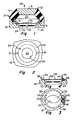
- the vibration attenuating device 10 of Fig. 1 of the drawings is comprised of a housing 12 that includes a spring element 14, made of elastomeric material and of generally conical hollow shape, secured to and between rigid housing members 16, 18 that are adapted for connection to members, such as the engine and frame of an automobile, in association in which device 10 is to be used.
- An interior variable volume or "working" chamber 20 of housing 12 is filled with hydraulic fluid such as water and/or alcohol or the like.
- the peripheral walls of chamber 20 are defined by inner surface portions of housing elements 14,16, 18 and by the inner surface of resilient diaphragm means 22 associated with rigid housing element 18.
- diaphragm 22 is bonded or otherwise suitably affixed about its periphery within an opening 24 extending partially or completely (as shown) through element 18.
- the central portion of the diaphragm 22 is free to flex freely along an axis orthogonal to its major surfaces. In the illustrated orientation of the diaphragm, the flexure axis thereof extends vertically.
- the central portion of diaphragm 22 undergoes oscillatory flexure and imparts oscillatory movement along its aforesaid flexure axis to a portion or slug 26 of the fluid within chamber 20.
- the fluid slug 26 overlies the central portion of diaphragm 22 and extends inwardly (upwardly as viewed in Fig. 1) a considerable distance therefrom.
- the inertia forces generated by the oscillating fluid slug 26 will minimize the dynamic stiffness of device 10. The particular excitation frequency at which this occurs is determined and controlled by tuning means to be now described.
- the tuning means comprises a thin annular tuning plate 28 having a central opening 30.
- Suitable fasteners 31 mount plate 28 upon the inner surface of housing member 18.
- the plate extends generally parallel to diaphragm 22, and is centered about the diaphragm's flexure axis.
- Plate 28 and diaphragm 22 are spaced sufficiently far apart as to prevent engagement between them as the diaphragm flexes, but are sufficiently close together as to insure that the oscillating fluid slug 26 projects through plate opening 30.
- plate opening 30 affects the size of fluid slug 26 and thus the inertial forces generated by its oscillation.
- device 10 may be tuned to reach its minimum dynamic stiffness at a particular desired high frequency. Decreasing the size of opening 30 decreases the frequency at which minimum stiffness is achieved, provided that the opening (or openings, if more than one is provided) of the tuning means is not so small as to significantly impede the movement through it of fluid slug 26. Free oscillatory movement of fluid slug 26 is desired, and is enhanced by the large ratio of the diameter of opening 30 to its length, i.e., to the thickness of plate 28. Such ratio is at least ten to one, and usually will be greater.
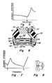
- Fig. 5 plot of the dynamic stiffness of device 10 against excitation frequency, minimum dynamic stiffness is realized at a particular high (i.e., greater than 100 Hz) frequency f n dependent upon the size of opening 30 of annular tuning plate 28.
- the Fig. 5 curve or plot would be shifted to the left by the use of tuning plate having a smaller opening 30, and to the right by the use of the plate having a larger opening.
- the dynamic stiffness at frequency f n may be considerably less than the static stiffness of device 10.
- device 10 might employ an adjustable tuning assembly 32 such as shown in Figs. 3 and 4.
- Assembly 32 has an elliptical opening 34, corresponding to the circular plate opening 30 of previously described plate 32, defined between a pair of arcuate plate elements 36, 38 having superimposed opposite end portions.
- a pin 40 adjacent one end of the assembly 32 mounts the same upon housing element 18 while permitting elements 36, 38 to undergo relative pivotal movement effective to vary the size of assembly opening 34.
- toothed surfaces 42 upon elements 36, 38 mesh with a gear 44 carried by and rotatable with a shaft 46 journalled within a bore of housing member 18.
- Shaft 46 is drivable in either direction by a flexible cable 48 connected thereto and extending therefrom to the exterior of device 10 in a manner similar to that illustrated in connection with the device 10' of Fig. 6, to be now described.
- the housing of device 10' includes a flexible bellows that underlies and is fixedly secured to housing element 18' so as to define therewith a second fluid chamber 52.
- Chamber 52 and the upper or "working" chamber 20' of device 10' are interconnected by an elongate slender passageway 54 provided within housing member 18' and having openings (not shown) at its opposite ends respectively communicating with chambers 20', 54.
- the stiffness characteristics of device 10 are affected by the fluid within passageway 54.
- the oscillatory flexure of diaphragm 22' produces synchronous oscillatory movement of axially aligned fluid slugs 26', 56, the latter being within expansion chamber 52 of device 10'.
- the tuning means associated with diaphragm 22, for the purpose of governing the high excitation frequency at which minimum dynamic stiffness occurs, may and illustratively does consist of two tuning assemblies 32' respectively mounted upon the upper and lower surfaces of housing member 18' so as to receive, within their central openings, respective ones of the fluid slugs 26', 56.
- assemblies 32, 32' While in some instances it might be desirable for assemblies 32, 32' to be adjustable independently of one another, they may be and illustratively are interconnected by a common shaft 46' so as to undergo simultaneous adjustment upon rotation of the flexible cable 48' connected to it. Cable 48' extends to the exterior of device 10 through a bore 58 directed through housing element 16 and containing suitable bushing and sealing elements 60.
- the Fig. 7 dynamic stiffness plot for device 10' illustrates two "notches" or valleys of minimum dynamic stiffness of the mount. The first of these occurs at a low (e.g., under 20 Hz) frequency f1 due to the inertia effect of the fluid within passageway 54 on device 10'. The second occurs at a high frequency f2 as a result of the inertia forces of oscillating fluid slugs 26', 56, and can be varied by adjustment of the tuning means of device 10'.
- a low e.g., under 20 Hz
- Fig. 8 of the drawings is a schematic representation of an adjustable device M, constructed in accordance with the present invention, mounting the engine E upon the frame F of an automobile or similar vehicle further equipped with a controller C that automatically adjusts or tunes device M in relation to changes in speed of engine E.
- controller C might adjust or tune device E in response to input from a sensor that detects frame vibrations capable of causing drone noise within the vehicle.
Landscapes
- Engineering & Computer Science (AREA)
- General Engineering & Computer Science (AREA)
- Mechanical Engineering (AREA)
- Combined Devices Of Dampers And Springs (AREA)
- Arrangement Or Mounting Of Propulsion Units For Vehicles (AREA)
- Vibration Prevention Devices (AREA)
- Apparatuses For Generation Of Mechanical Vibrations (AREA)
- Fluid-Damping Devices (AREA)
Priority Applications (1)
| Application Number | Priority Date | Filing Date | Title |
|---|---|---|---|
| AT86300701T ATE52584T1 (de) | 1985-02-22 | 1986-02-03 | Dynamischer schwingungsdaempfer mit traegheitsfluessigkeit. |
Applications Claiming Priority (2)
| Application Number | Priority Date | Filing Date | Title |
|---|---|---|---|
| US06/704,448 US4641808A (en) | 1985-02-22 | 1985-02-22 | Dynamic vibration attenuator utilizing inertial fluid |
| US704448 | 1985-02-22 |
Publications (3)
| Publication Number | Publication Date |
|---|---|
| EP0192371A2 EP0192371A2 (en) | 1986-08-27 |
| EP0192371A3 EP0192371A3 (en) | 1988-01-13 |
| EP0192371B1 true EP0192371B1 (en) | 1990-05-09 |
Family
ID=24829529
Family Applications (1)
| Application Number | Title | Priority Date | Filing Date |
|---|---|---|---|
| EP86300701A Expired - Lifetime EP0192371B1 (en) | 1985-02-22 | 1986-02-03 | Dynamic vibration attenuator utilizing inertial fluid |
Country Status (6)
| Country | Link |
|---|---|
| US (1) | US4641808A (ja) |
| EP (1) | EP0192371B1 (ja) |
| JP (1) | JPH0689802B2 (ja) |
| AT (1) | ATE52584T1 (ja) |
| CA (1) | CA1245679A (ja) |
| DE (1) | DE3671079D1 (ja) |
Families Citing this family (17)
| Publication number | Priority date | Publication date | Assignee | Title |
|---|---|---|---|---|
| JPS62180130A (ja) * | 1986-02-03 | 1987-08-07 | Honda Motor Co Ltd | 可変オリフイスを有する複合エンジンマウント |
| FR2596837B1 (fr) * | 1986-04-07 | 1990-06-22 | Hutchinson | Perfectionnements aux supports antivibratoires de type hydraulique |
| JPH0799189B2 (ja) * | 1986-06-12 | 1995-10-25 | 本田技研工業株式会社 | 流体封入型防振装置 |
| IT1197531B (it) * | 1986-10-31 | 1988-11-30 | Pirelli Accessori Ind | Dispositivo smorzatore |
| DE3701264A1 (de) * | 1987-01-17 | 1988-07-28 | Opel Adam Ag | Hydrolager |
| FR2610054B1 (fr) * | 1987-01-26 | 1991-08-16 | Hutchinson | Perfectionnements apportes aux supports antivibratoires hydrauliques |
| US4783062A (en) * | 1987-07-01 | 1988-11-08 | General Motors Corporation | Electronic hydraulic mount-internal solenoid |
| DE3721811A1 (de) * | 1987-07-02 | 1989-01-12 | Freudenberg Carl Fa | Motorlager |
| IT1211187B (it) * | 1987-07-07 | 1989-10-12 | Ages Spa | Supporto ammortizzante per la sospensione di un corpo oscillante ad una struttura di sopporto partico larmente per la sospensione del motore al telaio in un autoveicolo |
| US4789143A (en) * | 1987-09-14 | 1988-12-06 | General Motors Corporation | Electronic motor mount with rotary flow control valve |
| US4925162A (en) * | 1988-06-17 | 1990-05-15 | Bridgestone Corporation | Vibration isolating devices |
| US4969632A (en) * | 1989-08-10 | 1990-11-13 | Lord Corporation | Mount with adjustable length inertia track |
| US5788029A (en) * | 1993-08-18 | 1998-08-04 | Bell Helicopter | Vibration isolation system |
| US7270321B2 (en) * | 2002-11-06 | 2007-09-18 | Lord Corporation | Fluid-elastomeric damper assembly including internal pumping mechanism |
| US6758466B2 (en) * | 2002-11-06 | 2004-07-06 | Lord Corporation | Fluid-elastomeric damper assembly including internal pumping mechanism |
| JP4270502B2 (ja) * | 2004-02-13 | 2009-06-03 | 東海ゴム工業株式会社 | エンジンマウント |
| EP3603453A1 (en) | 2015-05-14 | 2020-02-05 | VIP Cinema LLC | Motor driven sloped floor recline mechanism for a theater seat |
Citations (2)
| Publication number | Priority date | Publication date | Assignee | Title |
|---|---|---|---|---|
| EP0110195A1 (de) * | 1982-11-30 | 1984-06-13 | METZELER Gesellschaft mit beschränkter Haftung | Zweikammer-Motorlager mit hydraulischer Dämpfung |
| EP0115417A2 (en) * | 1983-01-25 | 1984-08-08 | Avon Industrial Polymers Limited | Hydraulically damped mounting device |
Family Cites Families (19)
| Publication number | Priority date | Publication date | Assignee | Title |
|---|---|---|---|---|
| US3125186A (en) * | 1964-03-17 | Adjustable hydraulic shock absorbers | ||
| GB1138622A (en) * | 1965-05-26 | 1969-01-01 | Perkins Engines Ltd | Improvements relating to hydrodynamic brakes |
| DE2802896C2 (de) * | 1978-01-24 | 1982-09-23 | Audi Nsu Auto Union Ag, 7107 Neckarsulm | Gummilager mit hydraulischer Dämpfung |
| IT1110771B (it) * | 1979-02-09 | 1986-01-06 | Gomma Antivibranti Applic | Sopporto ammortizzante per la sospensione di un corpo oscillante ad una struttura di sopporto,particolarmente per la sospensione del motore al telaio di un autoveicolo |
| JPS56143835A (en) * | 1980-04-11 | 1981-11-09 | Tokai Rubber Ind Ltd | Vibration damping support |
| DE3027742A1 (de) * | 1980-07-22 | 1982-02-04 | Metzeler Kautschuk GmbH, 8000 München | Zweikammer-motorlager mit hydraulischer daempfung |
| US4401298A (en) * | 1980-11-18 | 1983-08-30 | Imperial Clevite Inc. | Flexible column viscous spring damper |
| JPS5820746U (ja) * | 1981-08-04 | 1983-02-08 | 本田技研工業株式会社 | 防振支持装置 |
| FR2522759A1 (fr) * | 1982-03-03 | 1983-09-09 | Hutchinson | Perfectionnements aux amortisseurs hydrauliques a membrane |
| JPS58163734U (ja) * | 1982-04-27 | 1983-10-31 | 三菱自動車工業株式会社 | 振動物体支持用マウント |
| DE3225700C1 (de) * | 1982-07-09 | 1983-11-17 | Fa. Carl Freudenberg, 6940 Weinheim | Elastisches Gummilager |
| DE3245653C2 (de) * | 1982-12-09 | 1986-11-06 | Metzeler Kautschuk GmbH, 8000 München | Zweikammer-Motorlager mit hydraulischer Dämpfung |
| JPS5994629U (ja) * | 1982-12-15 | 1984-06-27 | トヨタ自動車株式会社 | 防振ゴム装置 |
| JPS59113530U (ja) * | 1983-01-20 | 1984-07-31 | トヨタ自動車株式会社 | 防振ゴム装置 |
| DE3316025A1 (de) * | 1983-05-03 | 1984-11-08 | Tillmann 6108 Weiterstadt Freudenberg | Motorlager |
| SE449780B (sv) * | 1983-09-16 | 1987-05-18 | Trelleborg Ab | Vibrationsisolator med vetskedempning |
| JPS60184737A (ja) * | 1984-02-21 | 1985-09-20 | Honda Motor Co Ltd | 流体入りマウント |
| JPS60192195A (ja) * | 1984-03-13 | 1985-09-30 | 日産自動車株式会社 | パワ−ユニツトマウント装置 |
| DE3508823A1 (de) * | 1985-03-13 | 1986-09-18 | Josef Adolf 5410 Höhr-Grenzhausen Knopp | Duesenplatte fuer hydrolager, hydrobuchsen und aehnliche daempfungsteile |
-
1985
- 1985-02-22 US US06/704,448 patent/US4641808A/en not_active Expired - Fee Related
-
1986
- 1986-01-15 CA CA000499582A patent/CA1245679A/en not_active Expired
- 1986-02-03 AT AT86300701T patent/ATE52584T1/de not_active IP Right Cessation
- 1986-02-03 EP EP86300701A patent/EP0192371B1/en not_active Expired - Lifetime
- 1986-02-03 DE DE8686300701T patent/DE3671079D1/de not_active Expired - Lifetime
- 1986-02-21 JP JP61035434A patent/JPH0689802B2/ja not_active Expired - Lifetime
Patent Citations (2)
| Publication number | Priority date | Publication date | Assignee | Title |
|---|---|---|---|---|
| EP0110195A1 (de) * | 1982-11-30 | 1984-06-13 | METZELER Gesellschaft mit beschränkter Haftung | Zweikammer-Motorlager mit hydraulischer Dämpfung |
| EP0115417A2 (en) * | 1983-01-25 | 1984-08-08 | Avon Industrial Polymers Limited | Hydraulically damped mounting device |
Also Published As
| Publication number | Publication date |
|---|---|
| EP0192371A2 (en) | 1986-08-27 |
| US4641808A (en) | 1987-02-10 |
| EP0192371A3 (en) | 1988-01-13 |
| CA1245679A (en) | 1988-11-29 |
| ATE52584T1 (de) | 1990-05-15 |
| JPH0689802B2 (ja) | 1994-11-14 |
| DE3671079D1 (de) | 1990-06-13 |
| JPS61192940A (ja) | 1986-08-27 |
Similar Documents
| Publication | Publication Date | Title |
|---|---|---|
| EP0192371B1 (en) | Dynamic vibration attenuator utilizing inertial fluid | |
| US4969632A (en) | Mount with adjustable length inertia track | |
| EP0258998B1 (en) | Fluid filled vibration isolator having precisely adjustable dynamic operating characteristics | |
| EP0262544B1 (en) | Hydraulically damped mounting device | |
| US4720087A (en) | Inertia type fluid mount using electrorheological and other fluid | |
| EP0595591B1 (en) | A controllable support element | |
| US4971300A (en) | Motor mount having improved hydraulic damping | |
| EP0178652B1 (en) | Liquid-filled type vibration damping structure | |
| US6598864B2 (en) | Hydraulic two-chamber bearing for damping vibrations | |
| US5029825A (en) | Fluid filled engine mount | |
| EP1036952B1 (en) | Hydraulic vibration isolator | |
| KR100204905B1 (ko) | 감쇠력이 조절가능한 유체봉입식 엔진마운트 | |
| US6634629B1 (en) | Hydraulic engine mounting | |
| JPH08166037A (ja) | 防振装置 | |
| US5088699A (en) | Electrorheopectic fluid filled vibration damping mount for use with automotive engines and the like | |
| KR100192317B1 (ko) | 감쇠력이 조절가능한 유체봉입식 엔진마운트 | |
| KR200194941Y1 (ko) | 부싱타입의 액체봉입형 마운팅장치 | |
| KR0139440B1 (ko) | 방진장치 | |
| JP2011027158A (ja) | 防振装置 | |
| KR100243617B1 (ko) | 액체봉입식 엔진마운트 | |
| KR100246665B1 (ko) | 감쇠력이 조절가능한 유체봉입식 엔진마운트 | |
| KR100192491B1 (ko) | 자동차의 유체봉입식 엔진마운트의 구조 | |
| KR19980038210U (ko) | 감쇠력이 조절가능한 유체봉입식 엔진마운트 | |
| KR19980030131U (ko) | 감쇠력이 조절가능한 유체봉입식 엔진마운트 | |
| JPH04181040A (ja) | ダイナミックダンパ |
Legal Events
| Date | Code | Title | Description |
|---|---|---|---|
| PUAI | Public reference made under article 153(3) epc to a published international application that has entered the european phase |
Free format text: ORIGINAL CODE: 0009012 |
|
| AK | Designated contracting states |
Kind code of ref document: A2 Designated state(s): AT BE CH DE FR GB IT LI LU NL SE |
|
| PUAL | Search report despatched |
Free format text: ORIGINAL CODE: 0009013 |
|
| AK | Designated contracting states |
Kind code of ref document: A3 Designated state(s): AT BE CH DE FR GB IT LI LU NL SE |
|
| RAP1 | Party data changed (applicant data changed or rights of an application transferred) |
Owner name: LORD CORPORATION |
|
| 17P | Request for examination filed |
Effective date: 19880621 |
|
| 17Q | First examination report despatched |
Effective date: 19890419 |
|
| GRAA | (expected) grant |
Free format text: ORIGINAL CODE: 0009210 |
|
| AK | Designated contracting states |
Kind code of ref document: B1 Designated state(s): AT BE CH DE FR GB IT LI LU NL SE |
|
| PG25 | Lapsed in a contracting state [announced via postgrant information from national office to epo] |
Ref country code: NL Effective date: 19900509 Ref country code: LI Effective date: 19900509 Ref country code: CH Effective date: 19900509 Ref country code: BE Effective date: 19900509 Ref country code: AT Effective date: 19900509 |
|
| REF | Corresponds to: |
Ref document number: 52584 Country of ref document: AT Date of ref document: 19900515 Kind code of ref document: T |
|
| ITF | It: translation for a ep patent filed | ||
| REF | Corresponds to: |
Ref document number: 3671079 Country of ref document: DE Date of ref document: 19900613 |
|
| ET | Fr: translation filed | ||
| REG | Reference to a national code |
Ref country code: CH Ref legal event code: PL |
|
| NLV1 | Nl: lapsed or annulled due to failure to fulfill the requirements of art. 29p and 29m of the patents act | ||
| PG25 | Lapsed in a contracting state [announced via postgrant information from national office to epo] |
Ref country code: LU Free format text: LAPSE BECAUSE OF NON-PAYMENT OF DUE FEES Effective date: 19910228 |
|
| PLBE | No opposition filed within time limit |
Free format text: ORIGINAL CODE: 0009261 |
|
| STAA | Information on the status of an ep patent application or granted ep patent |
Free format text: STATUS: NO OPPOSITION FILED WITHIN TIME LIMIT |
|
| 26N | No opposition filed | ||
| ITTA | It: last paid annual fee | ||
| PGFP | Annual fee paid to national office [announced via postgrant information from national office to epo] |
Ref country code: FR Payment date: 19940111 Year of fee payment: 9 |
|
| PGFP | Annual fee paid to national office [announced via postgrant information from national office to epo] |
Ref country code: DE Payment date: 19940113 Year of fee payment: 9 |
|
| PGFP | Annual fee paid to national office [announced via postgrant information from national office to epo] |
Ref country code: SE Payment date: 19940114 Year of fee payment: 9 |
|
| PGFP | Annual fee paid to national office [announced via postgrant information from national office to epo] |
Ref country code: GB Payment date: 19940128 Year of fee payment: 9 |
|
| EAL | Se: european patent in force in sweden |
Ref document number: 86300701.9 |
|
| PG25 | Lapsed in a contracting state [announced via postgrant information from national office to epo] |
Ref country code: GB Effective date: 19950203 |
|
| PG25 | Lapsed in a contracting state [announced via postgrant information from national office to epo] |
Ref country code: SE Effective date: 19950204 |
|
| GBPC | Gb: european patent ceased through non-payment of renewal fee |
Effective date: 19950203 |
|
| PG25 | Lapsed in a contracting state [announced via postgrant information from national office to epo] |
Ref country code: FR Effective date: 19951031 |
|
| PG25 | Lapsed in a contracting state [announced via postgrant information from national office to epo] |
Ref country code: DE Effective date: 19951101 |
|
| EUG | Se: european patent has lapsed |
Ref document number: 86300701.9 |
|
| REG | Reference to a national code |
Ref country code: FR Ref legal event code: ST |
|
| PG25 | Lapsed in a contracting state [announced via postgrant information from national office to epo] |
Ref country code: IT Free format text: LAPSE BECAUSE OF NON-PAYMENT OF DUE FEES;WARNING: LAPSES OF ITALIAN PATENTS WITH EFFECTIVE DATE BEFORE 2007 MAY HAVE OCCURRED AT ANY TIME BEFORE 2007. THE CORRECT EFFECTIVE DATE MAY BE DIFFERENT FROM THE ONE RECORDED. Effective date: 20050203 |