EP0189902A2 - Hochdruckspritzrohr auf Taktbasis - Google Patents
Hochdruckspritzrohr auf Taktbasis Download PDFInfo
- Publication number
- EP0189902A2 EP0189902A2 EP86101113A EP86101113A EP0189902A2 EP 0189902 A2 EP0189902 A2 EP 0189902A2 EP 86101113 A EP86101113 A EP 86101113A EP 86101113 A EP86101113 A EP 86101113A EP 0189902 A2 EP0189902 A2 EP 0189902A2
- Authority
- EP
- European Patent Office
- Prior art keywords
- spray
- endless belt
- distance
- width
- nozzles
- Prior art date
- Legal status (The legal status is an assumption and is not a legal conclusion. Google has not performed a legal analysis and makes no representation as to the accuracy of the status listed.)
- Granted
Links
Images
Classifications
-
- B—PERFORMING OPERATIONS; TRANSPORTING
- B08—CLEANING
- B08B—CLEANING IN GENERAL; PREVENTION OF FOULING IN GENERAL
- B08B3/00—Cleaning by methods involving the use or presence of liquid or steam
- B08B3/02—Cleaning by the force of jets or sprays
- B08B3/022—Cleaning travelling work
Definitions
- the invention relates to a cleaning device for an endless belt with a spray tube which can be displaced axially transversely to the endless belt and has a plurality of spray nozzles and a drive device for the spray tube, the spray nozzles having a predetermined distance A and a spray width S.
- Endless belts are used for example in belt filter presses, and from time to time it is necessary to clean the sieve belts used.
- spray pipes are known which run perpendicular to the direction of movement of the endless belt and in which several nozzles are introduced which spray a water jet onto the surface of the endless belt.
- the spray tube moves continuously by a predetermined distance in its longitudinal axis so that the spray nozzles capture as many positions of the endless belt as possible.
- the object of the invention is to improve such a cleaning device so that a more reliable cleaning of the endless belt is achieved.
- the solution according to the invention enables a cycle operation in the sense that when the spray tube is stationary in one of its locking positions, the spray nozzles act on the endless belt in strips and carry out thorough cleaning there and then the spray tube is moved into the next locking position and the spray nozzles then adjacent strip paths act upon.
- This solution can be easily adapted to a wide range of applications and cleaning requirements and enables minimal water consumption with a given cleaning quality.
- a drive device 13 which can be designed hydraulically, pneumatically or electrically and which has a locking position R which cooperates with two locking positions R 1, R 2 on the spray tube 10.
- the distance x between the two locking positions Rl, R2 is chosen in the illustrated embodiment to be the same size as the spray width S.
Landscapes
- Superconductors And Manufacturing Methods Therefor (AREA)
- Cleaning By Liquid Or Steam (AREA)
- Vessels And Coating Films For Discharge Lamps (AREA)
- Nozzles (AREA)
- Cleaning In General (AREA)
- Treatment Of Fiber Materials (AREA)
- Paper (AREA)
- Jet Pumps And Other Pumps (AREA)
- Fluid-Pressure Circuits (AREA)
Abstract
Description
- Die Erfindung betrifft eine Reinigungsvorrichtung für ein Endlosband mit einem quer zum Endlosband axial verschiebbaren Spritzrohr mit mehreren Spritzdüsen und einer Antriebsvorrichtung für das Spritzrohr, wobei die Spritzdüsen einen vorgegebenen Abstand A und eine Spritzbreite S haben.
- Endlosbänder werden beispielsweise bei Bandfilterpressen eingesetzt, und von Zeit zu Zeit ist es erforderlich, eine Reinigung der verwendeten Siebbänder durchzuführen. Hierzu sind Spritzrohre bekannt, die senkrecht zur Bewegungsrichtung des Endlosbandes verlaufen und in denen mehrere Düsen eingebracht sind, die einen Wasserstrahl auf die Oberfläche des Endlosbandes spritzen. Dabei bewegt sich das Spritzrohr kontinuierlich um eine vorgegebene Strecke in seiner Längsachse, damit die Spritzdüsen möglichst alle Stellen des Endlosbandes erfassen.
- Es hat sich jedoch herausgestellt, daß bei der bisher verwendeten Betriebsart, bei welcher das Spritzrohr langsam oder schnell bewegt wird, immer wieder ungereinigte Leerstellen auf dem Band verbleiben.
- Aufgabe der Erfindung ist es, eine derartige Reinigungsvorrichtung so zu verbessern, daß eine zuverlässigere Reinigung des Endlosbandes erzielt wird.
- Erfindungsgemäß wird diese Aufgabe dadurch gelöst, daß der Abstand der Spritzrohre ein Mehrfaches der Spritzbreite beträgt, und daß das Spritzrohr auf seinem Verschiebeweg n = A/S Rastpositionen aufweist, deren Abstand etwa der Spritzbreite oder einem Bruchteil davon entspricht.
- Mit einer derartigen Anordnung ermöglicht die erfindungsgemäße Lösung einen Taktbetrieb in dem Sinne, daß bei feststehendem Spritzrohr in einer seiner Rastpositionen die Spritzdüsen das Endlosband streifenweise beaufschlagen und dort eine gründliche Reinigung durchführen und danach das Spritzrohr in die nächste Rastposition verschoben wird und die Spritzdüsen dann benachbarte Streifenbahnen beaufschlagen.
- Diese Lösung kann auf die verschiedensten Anwendungsbereiche und Reinigungungserfordemisse einfach abgestimmt werden und ermöglicht einen minimalen Wasserverbrauch bei vorgegebener Reinigungsqualität.
- Ein Ausführungsbeispiel der Erfindung wird anhand der Schemazeichnung näher erläutert:
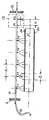
- Ein Spritzrohr 10 ist an seinen beiden Enden in Lagern 11 und 12 axial verschiebbar gehalten und wird über eine Leitug 14 mit Spritzwasser versorgt. Das Spritzwasser wird über Düsen S1...S5 nach unten abgegeben und beaufschlagt dort ein Endlosband 20, das um eine Walze 21 geführt ist. Der Abstand des Spritzrohres 10 von der Oberseite des Endlosbandes 20 und der Spritzwinkel α ist derart gewählt, daß sich bei einem vorgegebenen Abstand A der Spritzdüsen S1...S5 untereinander eine Spritzbreite S ergibt, die einen Teil des Endlosbandes 20 abdeckt.
- Zur axialen Verschiebung des Spritzrohres 10 ist dieses in eine Antriebsvorrichtung 13 geführt, die hydraulisch, pneumatisch oder elektrisch ausgestaltet sein kann und die eine Raststellung R aufweist, die mit zwei Raststellungen R 1, R 2 auf dem Spritzrohr 10 zusammenarbeitet. Der Abstand x der beiden Raststellungen Rl, R2 ist dabei beim dargestellten Ausführungsbeispiel gleich groß gewählt wie die Spritzbreite S.
- Die Reinigungsvorrichtung arbeitet wie folgt:
- Nachdem in der dargestellten Position eine ausreichende streifenweise Beaufschlagung des Endlosbandes 20 durchgeführt worden ist, wird die Antriebsvorrichtung 13 angesteuert, und diese verschiebt das Spritzrohr 10 nach rechts, bis dessen Rastposition R1 in Eingriff mit der Rastposition R der Antriebsvorrichtung 13 kommt. In dieser Position beaufschlagen dann die fünf Spritzdüsen S1...S5 die bisher freigebliebenen Streifen des Endlosbandes 20 und reinigen diese Bereiche.
- Beim dargestellten Ausführungsbeispiel sind fünf Spritzdüsen und zwei Rastpositionen dargestellt. Es versteht sich jedoch von selbst, daß die Anzahl der Spritzdüsen und die Anzahl der Rastpositionen auf die jeweiligen Erfordernisse ohne weiteres angepaßt werden kann.
Claims (3)
dadurch gekennzeichnet, daß der Abstand' (A) ein Mehrfaches der Spritzbreite (S) beträgt, und daß das Spritzrohr (10) auf seinem Verschiebeweg N = A/S Rastpositionen (R1, R2) aufweist, deren Abstand (x) etwa der Spritzbreite (S) oder einem Bruchteil davon entspricht.
Priority Applications (1)
| Application Number | Priority Date | Filing Date | Title |
|---|---|---|---|
| AT86101113T ATE47540T1 (de) | 1985-02-01 | 1986-01-28 | Hochdruckspritzrohr auf taktbasis. |
Applications Claiming Priority (2)
| Application Number | Priority Date | Filing Date | Title |
|---|---|---|---|
| DE8502656U | 1985-02-01 | ||
| DE19858502656U DE8502656U1 (de) | 1985-02-01 | 1985-02-01 | Reinigungsvorrichtung fuer ein endlosband |
Publications (3)
| Publication Number | Publication Date |
|---|---|
| EP0189902A2 true EP0189902A2 (de) | 1986-08-06 |
| EP0189902A3 EP0189902A3 (en) | 1987-10-21 |
| EP0189902B1 EP0189902B1 (de) | 1989-10-25 |
Family
ID=6776910
Family Applications (1)
| Application Number | Title | Priority Date | Filing Date |
|---|---|---|---|
| EP86101113A Expired EP0189902B1 (de) | 1985-02-01 | 1986-01-28 | Hochdruckspritzrohr auf Taktbasis |
Country Status (4)
| Country | Link |
|---|---|
| US (1) | US4788732A (de) |
| EP (1) | EP0189902B1 (de) |
| AT (1) | ATE47540T1 (de) |
| DE (2) | DE8502656U1 (de) |
Cited By (3)
| Publication number | Priority date | Publication date | Assignee | Title |
|---|---|---|---|---|
| DE9301274U1 (de) * | 1992-02-15 | 1993-03-25 | Babcock Textilmaschinen GmbH, 2105 Seevetal | Vorrichtung zur Wärmebehandlung von laufenden Warenbahnen |
| CN103008273A (zh) * | 2012-11-29 | 2013-04-03 | 广州南沙珠江啤酒有限公司 | 移动式双座阀排泄腔清洗装置 |
| EP2418022A4 (de) * | 2009-04-07 | 2013-12-18 | Kawasaki Heavy Ind Ltd | Vorrichtung und verfahren zur reinigung einer dünnschicht-solarzellenplatte mittels hochdruckflüssigkeitsstrahl |
Families Citing this family (6)
| Publication number | Priority date | Publication date | Assignee | Title |
|---|---|---|---|---|
| US5546622A (en) * | 1994-07-05 | 1996-08-20 | Mcalister; Ronald E. | Fabric processing apparatus and method of treating a continous length of tubular-knit fabric in tubular form |
| DE19527106A1 (de) * | 1995-04-15 | 1996-10-17 | Toni Gerteis | Verfahren und Vorrichtung zur kontinuierlichen Reinigung von Holzschleifbändern |
| GB2335213B (en) * | 1998-03-09 | 2000-09-13 | Sofitech Nv | Nozzle arrangement for well cleaning apparatus |
| EP2258639B1 (de) * | 2009-06-03 | 2012-01-04 | Fameccanica.Data S.p.A. | Fördervorrichtung für Laserbehandlungen |
| GB2489053A (en) * | 2011-03-18 | 2012-09-19 | Rockwash Prep & Store Ltd | A method and apparatus for washing rock samples |
| CN105126421A (zh) * | 2015-09-28 | 2015-12-09 | 江苏泰源环保科技有限公司 | 新型内径流格栅除污机 |
Family Cites Families (9)
| Publication number | Priority date | Publication date | Assignee | Title |
|---|---|---|---|---|
| US3135653A (en) * | 1961-11-03 | 1964-06-02 | Sandy Hill Iron & Brass Works | Felt conditioner |
| DE1196049B (de) * | 1962-02-03 | 1965-07-01 | Schilde Maschb Ag | Vorrichtung zur Oberflaechenbehandlung mit Fluessigkeiten von Metallgegenstaenden |
| CH438594A (de) * | 1966-05-31 | 1967-06-30 | Concast Ag | Verfahren und Vorrichtung zum Kühlen von Stranggussmaterial |
| US3793054A (en) * | 1971-07-06 | 1974-02-19 | Ppg Industries Inc | Angled crossfire rinses |
| US3739605A (en) * | 1971-12-30 | 1973-06-19 | Bird Machine Co | Cleaning apparatus for materials moving in endless path |
| US3910815A (en) * | 1974-03-26 | 1975-10-07 | Westvaco Corp | Method and apparatus for papermachine felt cleaning |
| US4087320A (en) * | 1976-09-03 | 1978-05-02 | Huyck Corporation | Apparatus for cleaning an endless belt having an affixed signal element |
| US4397694A (en) * | 1979-12-28 | 1983-08-09 | Deutsche Texaco Aktiengesellschaft | Spray nozzle assembly for filter devices |
| JPS6017193A (ja) * | 1983-07-09 | 1985-01-29 | 中村 徹 | ウエツトフエルト等の洗浄用シヤワ−パイプの摺動装置 |
-
1985
- 1985-02-01 DE DE19858502656U patent/DE8502656U1/de not_active Expired
-
1986
- 1986-01-28 DE DE8686101113T patent/DE3666547D1/de not_active Expired
- 1986-01-28 AT AT86101113T patent/ATE47540T1/de not_active IP Right Cessation
- 1986-01-28 EP EP86101113A patent/EP0189902B1/de not_active Expired
- 1986-01-30 US US06/824,200 patent/US4788732A/en not_active Expired - Fee Related
Cited By (5)
| Publication number | Priority date | Publication date | Assignee | Title |
|---|---|---|---|---|
| DE9301274U1 (de) * | 1992-02-15 | 1993-03-25 | Babcock Textilmaschinen GmbH, 2105 Seevetal | Vorrichtung zur Wärmebehandlung von laufenden Warenbahnen |
| EP2418022A4 (de) * | 2009-04-07 | 2013-12-18 | Kawasaki Heavy Ind Ltd | Vorrichtung und verfahren zur reinigung einer dünnschicht-solarzellenplatte mittels hochdruckflüssigkeitsstrahl |
| US9079226B2 (en) | 2009-04-07 | 2015-07-14 | Kawasaki Jukogyo Kabushiki Kaisha | High-pressure liquid jet cleaner and high-pressure liquid jet cleaning method for cleaning thin film solar cell panel |
| CN103008273A (zh) * | 2012-11-29 | 2013-04-03 | 广州南沙珠江啤酒有限公司 | 移动式双座阀排泄腔清洗装置 |
| CN103008273B (zh) * | 2012-11-29 | 2014-11-05 | 广州南沙珠江啤酒有限公司 | 移动式双座阀排泄腔清洗装置 |
Also Published As
| Publication number | Publication date |
|---|---|
| ATE47540T1 (de) | 1989-11-15 |
| US4788732A (en) | 1988-12-06 |
| DE3666547D1 (en) | 1989-11-30 |
| EP0189902A3 (en) | 1987-10-21 |
| DE8502656U1 (de) | 1985-05-02 |
| EP0189902B1 (de) | 1989-10-25 |
Similar Documents
| Publication | Publication Date | Title |
|---|---|---|
| DE1652061C3 (de) | Bandschleifmaschine zum Feinschleifen, insbesondere Feinstschleifen großflächiger plattenförmiger Werkstücke | |
| EP0189902B1 (de) | Hochdruckspritzrohr auf Taktbasis | |
| DE3133438C2 (de) | Verfahren und Vorrichtung zum automatischen Wechsen gefüllter Kannen gegen leere Kannen an einer Doppelkopfstrecke | |
| DE2716247B2 (de) | Tischanordnung zum Festklemmen und Nachführen des Nähgutes in einer automatischen Nähmaschine | |
| DD283590A5 (de) | Vorrichtung zur zufuehrung von gegenstaenden zu einer arbeitsstation | |
| EP0603647B1 (de) | Vorrichtung zum kontinuierlichen Herstellen von Schaumstoffbahnen, insbesondere Hartschaumstoffplatten | |
| EP0629425A1 (de) | Bandfiltereinrichtung zur Reinigung von Bearbeitungsflüssigkeiten | |
| DE3779923T2 (de) | Foerderanlage. | |
| DE2120693A1 (de) | Vorrichtung zur kontinuierlichen Förderung länglicher Gegenstände | |
| EP1700643A2 (de) | Behälteraufgabe | |
| DE2840974C2 (de) | Endlose Gliederkette zum Transport von Gegenständen | |
| EP1447467B1 (de) | Vorrichtung zum Behandeln, Dämpfen, Färben, Appretieren, Waschen od. dgl. mindestens eines umlaufenden Bandes | |
| DE2823047C2 (de) | Vorrichtung zum Quer- und Längsfalten von Wäschestücken | |
| DE19523621C2 (de) | Vorrichtung zum Behandeln, Färben, Appretieren, Waschen o. dgl. von laufenden, schmalen textilen Bändern | |
| CH663604A5 (de) | Umlenkeinrichtung fuer einen schuppenstrom. | |
| EP0445256B1 (de) | Anlage für das entwässernde pressen einer feststoffmatte | |
| DE2039961A1 (de) | Vorrichtung zum Reinigen von Gegenstaenden,insbesondere zum Entfernen von Spaenen von bearbeiteten Werkstuecken | |
| DE2265037B2 (de) | Vorrichtung zum Schmieren der Kette eines Förderers, insbesondere eines Kreisförderers | |
| DE4239259A1 (de) | Einrichtung zum Waschen von Teilen | |
| DE2318261A1 (de) | Verfahren und vorrichtung zum stapeln von zigaretten in einen behaelter | |
| EP0797948A1 (de) | Vorrichtung zum Reinigen einer einen Schwamm aufweisenden Schwammscheibe | |
| DE2644849C3 (de) | Walk- und Waschmaschine für breitgeführte Textilware, insbesondere Filzbahnen | |
| DE2255617C3 (de) | Glasiervorrichtung | |
| DE69109967T2 (de) | Mechanisches Fördersystem zum Drehen und Aufteilen einer Reihe von Packungen. | |
| DE4134340A1 (de) | Vorrichtung zum ziehen eines langgestreckten profilkoerpers |
Legal Events
| Date | Code | Title | Description |
|---|---|---|---|
| PUAI | Public reference made under article 153(3) epc to a published international application that has entered the european phase |
Free format text: ORIGINAL CODE: 0009012 |
|
| AK | Designated contracting states |
Kind code of ref document: A2 Designated state(s): AT BE CH DE FR GB IT LI LU NL SE |
|
| PUAL | Search report despatched |
Free format text: ORIGINAL CODE: 0009013 |
|
| AK | Designated contracting states |
Kind code of ref document: A3 Designated state(s): AT BE CH DE FR GB IT LI LU NL SE |
|
| 17P | Request for examination filed |
Effective date: 19880229 |
|
| 17Q | First examination report despatched |
Effective date: 19890112 |
|
| GRAA | (expected) grant |
Free format text: ORIGINAL CODE: 0009210 |
|
| AK | Designated contracting states |
Kind code of ref document: B1 Designated state(s): AT BE CH DE FR GB IT LI LU NL SE |
|
| PG25 | Lapsed in a contracting state [announced via postgrant information from national office to epo] |
Ref country code: IT Free format text: LAPSE BECAUSE OF FAILURE TO SUBMIT A TRANSLATION OF THE DESCRIPTION OR TO PAY THE FEE WITHIN THE PRE;WARNING: LAPSES OF ITALIAN PATENTS WITH EFFECTIVE DATE BEFORE 2007 MAY HAVE OCCURRED AT ANY TIME BEFORE 2007. THE CORRECT EFFECTIVE DATE MAY BE DIFFERENT FROM THE ONE RECORDED.SCRIBED TIME-LIMIT Effective date: 19891025 Ref country code: SE Effective date: 19891025 Ref country code: GB Effective date: 19891025 |
|
| REF | Corresponds to: |
Ref document number: 47540 Country of ref document: AT Date of ref document: 19891115 Kind code of ref document: T |
|
| REF | Corresponds to: |
Ref document number: 3666547 Country of ref document: DE Date of ref document: 19891130 |
|
| ET | Fr: translation filed | ||
| PG25 | Lapsed in a contracting state [announced via postgrant information from national office to epo] |
Ref country code: AT Effective date: 19900128 |
|
| PGFP | Annual fee paid to national office [announced via postgrant information from national office to epo] |
Ref country code: LU Payment date: 19900130 Year of fee payment: 5 |
|
| PG25 | Lapsed in a contracting state [announced via postgrant information from national office to epo] |
Ref country code: LU Free format text: LAPSE BECAUSE OF NON-PAYMENT OF DUE FEES Effective date: 19900131 Ref country code: CH Effective date: 19900131 Ref country code: LI Effective date: 19900131 |
|
| GBV | Gb: ep patent (uk) treated as always having been void in accordance with gb section 77(7)/1977 [no translation filed] | ||
| PLBE | No opposition filed within time limit |
Free format text: ORIGINAL CODE: 0009261 |
|
| STAA | Information on the status of an ep patent application or granted ep patent |
Free format text: STATUS: NO OPPOSITION FILED WITHIN TIME LIMIT |
|
| REG | Reference to a national code |
Ref country code: CH Ref legal event code: PL |
|
| 26N | No opposition filed | ||
| PGFP | Annual fee paid to national office [announced via postgrant information from national office to epo] |
Ref country code: BE Payment date: 19901228 Year of fee payment: 6 |
|
| PG25 | Lapsed in a contracting state [announced via postgrant information from national office to epo] |
Ref country code: BE Effective date: 19920131 |
|
| BERE | Be: lapsed |
Owner name: GEBR. BELLMER G.M.B.H. & CO. K.G. MASCHINENFABRIK Effective date: 19920131 |
|
| PGFP | Annual fee paid to national office [announced via postgrant information from national office to epo] |
Ref country code: NL Payment date: 19930131 Year of fee payment: 8 |
|
| PG25 | Lapsed in a contracting state [announced via postgrant information from national office to epo] |
Ref country code: NL Effective date: 19940801 |
|
| NLV4 | Nl: lapsed or anulled due to non-payment of the annual fee | ||
| PGFP | Annual fee paid to national office [announced via postgrant information from national office to epo] |
Ref country code: DE Payment date: 19941114 Year of fee payment: 10 |
|
| PGFP | Annual fee paid to national office [announced via postgrant information from national office to epo] |
Ref country code: FR Payment date: 19950116 Year of fee payment: 10 |
|
| PG25 | Lapsed in a contracting state [announced via postgrant information from national office to epo] |
Ref country code: FR Effective date: 19960930 |
|
| PG25 | Lapsed in a contracting state [announced via postgrant information from national office to epo] |
Ref country code: DE Effective date: 19961001 |
|
| REG | Reference to a national code |
Ref country code: FR Ref legal event code: ST |