EP0189190A2 - Système de commande de papillon d'accélérateur de moteur à combustion interne - Google Patents
Système de commande de papillon d'accélérateur de moteur à combustion interne Download PDFInfo
- Publication number
- EP0189190A2 EP0189190A2 EP86100829A EP86100829A EP0189190A2 EP 0189190 A2 EP0189190 A2 EP 0189190A2 EP 86100829 A EP86100829 A EP 86100829A EP 86100829 A EP86100829 A EP 86100829A EP 0189190 A2 EP0189190 A2 EP 0189190A2
- Authority
- EP
- European Patent Office
- Prior art keywords
- throttle valve
- accelerator
- amount
- opening
- throttle
- Prior art date
- Legal status (The legal status is an assumption and is not a legal conclusion. Google has not performed a legal analysis and makes no representation as to the accuracy of the status listed.)
- Granted
Links
- 238000002485 combustion reaction Methods 0.000 title claims description 6
- 230000015654 memory Effects 0.000 claims description 5
- 239000000446 fuel Substances 0.000 description 16
- 239000007789 gas Substances 0.000 description 8
- 230000004044 response Effects 0.000 description 7
- 238000002347 injection Methods 0.000 description 4
- 239000007924 injection Substances 0.000 description 4
- 230000006870 function Effects 0.000 description 3
- QVGXLLKOCUKJST-UHFFFAOYSA-N atomic oxygen Chemical compound [O] QVGXLLKOCUKJST-UHFFFAOYSA-N 0.000 description 2
- 239000001301 oxygen Substances 0.000 description 2
- 229910052760 oxygen Inorganic materials 0.000 description 2
- 238000011144 upstream manufacturing Methods 0.000 description 2
- 230000001133 acceleration Effects 0.000 description 1
- 230000002411 adverse Effects 0.000 description 1
- 230000003197 catalytic effect Effects 0.000 description 1
- 238000004140 cleaning Methods 0.000 description 1
- 239000002826 coolant Substances 0.000 description 1
- 230000000881 depressing effect Effects 0.000 description 1
- 230000000977 initiatory effect Effects 0.000 description 1
- 230000035939 shock Effects 0.000 description 1
- XLYOFNOQVPJJNP-UHFFFAOYSA-N water Substances O XLYOFNOQVPJJNP-UHFFFAOYSA-N 0.000 description 1
Images


Classifications
-
- F—MECHANICAL ENGINEERING; LIGHTING; HEATING; WEAPONS; BLASTING
- F02—COMBUSTION ENGINES; HOT-GAS OR COMBUSTION-PRODUCT ENGINE PLANTS
- F02D—CONTROLLING COMBUSTION ENGINES
- F02D11/00—Arrangements for, or adaptations to, non-automatic engine control initiation means, e.g. operator initiated
- F02D11/06—Arrangements for, or adaptations to, non-automatic engine control initiation means, e.g. operator initiated characterised by non-mechanical control linkages, e.g. fluid control linkages or by control linkages with power drive or assistance
- F02D11/10—Arrangements for, or adaptations to, non-automatic engine control initiation means, e.g. operator initiated characterised by non-mechanical control linkages, e.g. fluid control linkages or by control linkages with power drive or assistance of the electric type
- F02D11/105—Arrangements for, or adaptations to, non-automatic engine control initiation means, e.g. operator initiated characterised by non-mechanical control linkages, e.g. fluid control linkages or by control linkages with power drive or assistance of the electric type characterised by the function converting demand to actuation, e.g. a map indicating relations between an accelerator pedal position and throttle valve opening or target engine torque
Definitions
- This invention relates to a throttle valve control system for an internal combustion engine, and more particularly to a system for electrically controlling the throttle valve in response to operation of the accelerator.
- the conventional electric control type throttle valve control system is disadvantageous in that the amount of intake air does not linearly change with respect to the amount of depression of the accelerator pedal since the throttle valve and the accelerator are operatively connected so that the opening degree of the throttle valve linearly changes with respect to the amount of operation of the accelerator as in the conventional mechanical throttle valve control system and the change in the effective opening area of the intake passage for a given change in the opening degree of the throttle valve differs with the opening degree of the throttle valve. Therefore, during cruising in which the amount of operation of the accelerator is intermediate, a slight change in the amount of operation of the accelerator reduces or increases intake air by a large amount so as to adversely affect stability during cruising.
- the primary object of the present invention is to provide an electric control type throttle valve control system in which the amount of-intake air is linearly related to the amount of operation of the accelerator, whereby stability during cruising can be ensured, acceleration during heavy load operation can be improved and response of the engine upon starting can be improved.
- the throttle valve control system in accordance with the present invention comprises an accelerator position sensor for detecting the amount of operation of the accelerator, a throttle valve opening degree determining means which receives the output of the accelerator position sensor and determines the opening degree of the throttle valve, and a throttle valve driving means which drives the throttle valve to the position corresponding to the opening degree determined by the throttle valve opening degree determining means, the throttle valve opening degree determining means being arranged to determine the opening degree of the throttle valve with respect to the amount of operation of the accelerator so that the change in the opening degree of the throttle valve for a given change in the amount of operation of the accelerator is relatively small when the amount of operation of the accelerator is in an intermediate range and is relatively large when the amount of operation of the accelerator is above or below the intermediate range.
- the accelerator operation-intake air amount characteristics (the relation between the amount of operation of the accelerator and the amount of intake air introduced into the combustion chamber) can be made substantially linear.
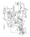
- an internal combustion engine 1 is provided with an intake passage 2.
- a throttle valve 3 which is opened and closed by a throttle actuator 4 which may be a stepping motor, a DC motor or the like.
- a vane type airflow meter 5 is disposed in the intake passage 2 upstream of the throttle valve 3, and an air cleaner 6 is mounted on the upstream end of the intake passage 2.
- a fuel injection valve 7 is disposed near the downstream end of the intake passage 2.
- the fuel injection valve 7 is connected to a fuel reservoir 9 by way of a fuel feed line 8.
- a fuel pump 10 and a fuel filter 11 are provided in the fuel feed line 8.
- a fuel return passage 12 connects the fuel reservoir 9 and a portion of the fuel feed line 8 downstream of the fuel filter 11, and a fuel pressure regulator 13 is provided in the fuel return passage 12, whereby fuel is fed to the fuel injection valve 7 under a fixed pressure.
- An exhaust passage 14 of the engine 1 is provided with a catalytic convertor 15 for cleaning exhaust gas, and an exhaust gas recirculation system 16 is provided between the intake passage 2 and the exhaust passage 14. That is, one end of an exhaust gas recirculation passage 17 is connected to the exhaust passage 14 and the other end of the same is connected to the intake passage 2.
- the exhaust gas recirculation passage 17 is provided with an exhaust gas recirculation valve 18 which is driven by a solenoid 19.
- the engine 1 is further provided with an accelerator pedal 20, battery 21, igniter 22, rpm sensor 23 for detecting the engine speed by way of the rotational angle of a distributor, accelerator position sensor 24 for detecting the amount of operation of the accelerator pedal 20, water temperature sensor 25 for detecting the temperature of engine coolant, intake air temperature sensor 26 for detecting the temperature of intake air, throttle position sensor 27 for detecting the opening degree of the throttle valve 3, oxygen sensor 28 for detecting the oxygen concentration in exhaust gas and computer unit 29 for controlling the throttle opening degree, fuel injection amount, exhaust gas recirculation amount and ignition timing.
- accelerator pedal 20 battery 21, igniter 22, rpm sensor 23 for detecting the engine speed by way of the rotational angle of a distributor
- accelerator position sensor 24 for detecting the amount of operation of the accelerator pedal 20
- water temperature sensor 25 for detecting the temperature of engine coolant
- intake air temperature sensor 26 for detecting the temperature of intake air
- throttle position sensor 27 for detecting the opening degree of the throttle valve 3
- oxygen sensor 28 for detecting the oxygen concentration in exhaust gas
- computer unit 29 for controlling
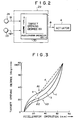
- the computer unit 29 includes a function generator 30 which generates a target throttle opening degree 6 for a given amount of operation a of the accelerator pedal and a given engine rpm which are respectively input from the accelerator position sensor 24 and the rpm sensor 23. That is, the detected amount of operation a of the accelerator pedal 20 and the detected engine rpm are address-input into a predetermined two-dimensional memory map as a x value and a y value, and a stored value corresponding to the x and y values, i.e., the target throttle opening degree e is read out.
- the function generator 30 has a plurality of such maps (in which the amount of operation a of the accelerator pedal 20 and the throttle opening degree 0 are related to each other) and selects one of them for a given engine rpm.
- the function generator 30 has three such maps as shown by characteristic curves a to c in Figure 3.
- Each characteristic curve is arranged so that the change in the throttle opening degree for a given change in the amount of operation of the accelerator pedal is relatively small when the amount of operation of the accelerator is in-a predetermined range (indicated at Al, A2 and A3 in the respective characteristic curves a, b and c) and is relatively large when the amount of operation of the accelerator pedal is above or below the predetermined range.
- the computer unit 29 selects one of the characteristic curves a to c so that the throttle opening degree for a given amount of operation of the accelerator pedal is increased as the engine rpm increases. That is, among the three characteristic curves a to c, the characteristic curve a is for the highest engine speed and the characteristic curve c is for the lowest engine speed.
- the maximum amount of intake air is determined by the engine rpm and accordingly, even if the throttle valve is opened beyond the opening degree corresponding to the maximum amount of intake air, the amount of intake air does not change. Accordingly, it is preferred from the viewpoint of efficiency of control that the throttle valve be not opened beyond the opening degree corresponding to the maximum amount of intake air determined by the engine rpm. This is the reason why a plurality of characteristic curves are prepared.
- dotted line d shows the same characteristic curve in the conventional mechanical throttle valve control system or the electric control type throttle valve control system in accordance with the prior art.
- step Sl the engine rpm R detected by the engine rpm sensor 23 is read in, and in step S2, one of the characteristic curves a to c is selected according to the engine rpm R.
- the curve a is selected
- the curve b is selected
- the curve c is selected.
- step S3 the amount of operation a of the accelerator pedal 20 detected by the accelerator position sensor 24 is read in, and in step S4, the target opening degree 6 of the throttle valve 3 corresponding to the detected amount of operation a of the accelerator pedal 20 is read from the characteristic curve selected in the step S2. Then in step S5, an electric signal corresponding to the read-out target opening degree 6 is delivered to the throttle actuator 4.
- the electric signal may represent the number of steps in the case that the throttle actuator is a stepping motor.
- lines e and g show accelerator operation-intake air amount characteristics of the throttle valve control system in accordance with this embodiment at 4000 rpm and 2000 rpm, respectively, while lines f and h show the same characteristics of the throttle valve control system in accordance with the prior art at 4000 rpm and 2000 rpm, respectively.
- These lines are obtained by measuring the amount of intake air while the amount of operation a of the accelerator pedal 20 is changed with the engine rpm fixed at 4000 rpm and 2000 rpm.
- the characteristic curves e to h have a point at which the inclination sharply changes
- the characteristic curves e and g for the control system of the present invention are superior to those f and h in linearity.
- the inclination is larger in the range of the amount of operation of the accelerator pedal smaller than the point at which the inclination sharply changes.
- a sufficient amount of intake air can be obtained with a quick response to operation of the accelerator pedal in the range in which the amount of operation of the accelerator pedal is relatively small and accordingly the vehicle can be smoothly started.
- the change in the amount of intake air for a given change in the amount of operation is relatively small and accordingly, stability in the cruising can be improved.
- the accelerator operation- throttle valve opening degree characteristics may be changed according to other factors such as the amount of operation of the accelerator pedal upon initiation of depression of the same, the depressing speed of the accelerator pedal or the like.
- said computer unit 29 accomplishes control on the amount of fuel-to be injected, ignition timing and amount of exhaust gas to be circulated, such controls do not form a part of this invention and accordingly will not be described in detail here.
Landscapes
- Engineering & Computer Science (AREA)
- Chemical & Material Sciences (AREA)
- Combustion & Propulsion (AREA)
- Mechanical Engineering (AREA)
- General Engineering & Computer Science (AREA)
- Electrical Control Of Air Or Fuel Supplied To Internal-Combustion Engine (AREA)
Applications Claiming Priority (2)
| Application Number | Priority Date | Filing Date | Title |
|---|---|---|---|
| JP60012007A JPS61171843A (ja) | 1985-01-24 | 1985-01-24 | エンジンのスロツトル弁制御装置 |
| JP12007/85 | 1985-01-24 |
Publications (3)
| Publication Number | Publication Date |
|---|---|
| EP0189190A2 true EP0189190A2 (fr) | 1986-07-30 |
| EP0189190A3 EP0189190A3 (en) | 1987-12-09 |
| EP0189190B1 EP0189190B1 (fr) | 1990-04-11 |
Family
ID=11793528
Family Applications (1)
| Application Number | Title | Priority Date | Filing Date |
|---|---|---|---|
| EP86100829A Expired - Lifetime EP0189190B1 (fr) | 1985-01-24 | 1986-01-22 | Système de commande de papillon d'accélérateur de moteur à combustion interne |
Country Status (4)
| Country | Link |
|---|---|
| US (1) | US4691677A (fr) |
| EP (1) | EP0189190B1 (fr) |
| JP (1) | JPS61171843A (fr) |
| DE (1) | DE3670342D1 (fr) |
Cited By (5)
| Publication number | Priority date | Publication date | Assignee | Title |
|---|---|---|---|---|
| EP0352657A2 (fr) * | 1988-07-29 | 1990-01-31 | Hitachi, Ltd. | Méthode et dispositif pour le réglage du degré d'ouverture de la soupape d'étranglement d'un moteur à combustion interne |
| GB2281638A (en) * | 1993-09-03 | 1995-03-08 | Kubota Kk | Control system for a hydraulic activator |
| WO1995027237A1 (fr) * | 1994-04-01 | 1995-10-12 | Asia Motors Co., Inc. | Dispositif de commande de la pedale d'accelerateur d'un vehicule |
| US6276333B1 (en) | 1998-09-17 | 2001-08-21 | Nissan Motor Co., Ltd. | Throttle control for engine |
| DE4223782B4 (de) * | 1992-07-18 | 2010-05-06 | Bayerische Motoren Werke Aktiengesellschaft | Ansaugluftmengensteuereinrichtung für eine Brennkraftmaschine eines Kraftfahrzeugs |
Families Citing this family (37)
| Publication number | Priority date | Publication date | Assignee | Title |
|---|---|---|---|---|
| JPS62288343A (ja) * | 1986-06-06 | 1987-12-15 | Honda Motor Co Ltd | 内燃エンジンの絞り弁制御装置 |
| JP2606824B2 (ja) * | 1986-06-06 | 1997-05-07 | 本田技研工業株式会社 | 車載内燃エンジンの絞り弁制御装置 |
| JPS62298642A (ja) * | 1986-06-18 | 1987-12-25 | Honda Motor Co Ltd | 内燃エンジンの絞り弁制御装置 |
| DE3721605A1 (de) * | 1986-07-01 | 1988-01-14 | Mazda Motor | Steuerungssystem fuer verbrennungsmotoren |
| US4862854A (en) * | 1987-04-06 | 1989-09-05 | Mazda Motor Corporation | Control systems for vehicle engines |
| US5018408A (en) * | 1987-09-26 | 1991-05-28 | Mazda Motor Corporation | Control systems for power trains provided in vehicles |
| DE3843056A1 (de) * | 1987-12-23 | 1989-07-06 | Mazda Motor | Anordnung zur motorleistungssteuerung |
| US4831985A (en) * | 1988-02-17 | 1989-05-23 | Mabee Brian D | Throttle control system |
| JP2506150B2 (ja) * | 1988-06-03 | 1996-06-12 | 株式会社日立製作所 | 内燃機関のスロットル制御装置 |
| JPH024942U (fr) * | 1988-06-24 | 1990-01-12 | ||
| US5002028A (en) * | 1988-07-27 | 1991-03-26 | Honda Giken Kogyo Kabushiki Kaisha | Throttle control system for vehicular internal combustion engine |
| US4901695A (en) * | 1988-10-20 | 1990-02-20 | Delco Electronics Corporation | Dual slope engine drive-by-wire drive circuit |
| JPH05248282A (ja) * | 1992-03-06 | 1993-09-24 | Mazda Motor Corp | エンジンのスロットル弁制御装置 |
| JP2001303987A (ja) * | 2000-04-21 | 2001-10-31 | Toyota Motor Corp | 筒内噴射式内燃機関のスロットル制御装置 |
| US6915778B2 (en) * | 2002-04-22 | 2005-07-12 | Mark Clemence | Throttle modulation device for combustion engine |
| FR2838774B1 (fr) * | 2002-04-22 | 2005-04-08 | Siemens Vdo Automotive | Procede et dispositif de controle de moteur vehicule |
| US7018442B2 (en) * | 2003-11-25 | 2006-03-28 | Caterpillar Inc. | Method and apparatus for regenerating NOx adsorbers |
| AU2011261248B2 (en) | 2010-06-03 | 2015-09-17 | Polaris Industries Inc. | Electronic throttle control |
| US8989928B2 (en) * | 2011-01-20 | 2015-03-24 | GM Global Technology Operations LLC | Watercraft throttle control systems and methods |
| US8731749B2 (en) | 2011-01-20 | 2014-05-20 | GM Global Technology Operations LLC | System and method for operating a vehicle cruise control system |
| US9233744B2 (en) | 2011-01-20 | 2016-01-12 | GM Global Technology Operations LLC | Engine control system and method for a marine vessel |
| US9127604B2 (en) | 2011-08-23 | 2015-09-08 | Richard Stephen Davis | Control system and method for preventing stochastic pre-ignition in an engine |
| US9097196B2 (en) | 2011-08-31 | 2015-08-04 | GM Global Technology Operations LLC | Stochastic pre-ignition detection systems and methods |
| KR101360042B1 (ko) * | 2011-12-01 | 2014-02-07 | 기아자동차주식회사 | 가변 흡기 시스템 |
| US8776737B2 (en) | 2012-01-06 | 2014-07-15 | GM Global Technology Operations LLC | Spark ignition to homogenous charge compression ignition transition control systems and methods |
| WO2013137387A1 (fr) * | 2012-03-15 | 2013-09-19 | 日産自動車株式会社 | Dispositif de commande de sortie de véhicule |
| US9121362B2 (en) | 2012-08-21 | 2015-09-01 | Brian E. Betz | Valvetrain fault indication systems and methods using knock sensing |
| US9133775B2 (en) | 2012-08-21 | 2015-09-15 | Brian E. Betz | Valvetrain fault indication systems and methods using engine misfire |
| US9205717B2 (en) | 2012-11-07 | 2015-12-08 | Polaris Industries Inc. | Vehicle having suspension with continuous damping control |
| US8973429B2 (en) | 2013-02-25 | 2015-03-10 | GM Global Technology Operations LLC | System and method for detecting stochastic pre-ignition |
| US9683497B2 (en) * | 2013-10-25 | 2017-06-20 | Ford Global Technologies, Llc | Methods and systems for adjusting engine airflow based on output from an oxygen sensor |
| CA3226026A1 (fr) | 2014-10-31 | 2016-05-06 | Polaris Industries Inc. | Systeme et procede de commande d'un vehicule |
| CN116176201A (zh) | 2016-11-18 | 2023-05-30 | 北极星工业有限公司 | 具有可调节悬架的车辆 |
| US10406884B2 (en) | 2017-06-09 | 2019-09-10 | Polaris Industries Inc. | Adjustable vehicle suspension system |
| US10987987B2 (en) | 2018-11-21 | 2021-04-27 | Polaris Industries Inc. | Vehicle having adjustable compression and rebound damping |
| JP7251461B2 (ja) * | 2019-12-13 | 2023-04-04 | トヨタ自動車株式会社 | 制御システム |
| WO2022016155A1 (fr) | 2020-07-17 | 2022-01-20 | Polaris Industries Inc. | Suspensions réglables et fonctionnement de véhicule pour véhicules de loisir hors-route |
Citations (6)
| Publication number | Priority date | Publication date | Assignee | Title |
|---|---|---|---|---|
| GB1133721A (en) * | 1965-01-29 | 1968-11-13 | Smiths Industries Ltd | Improvements in or relating to variable ratio transmission devices for incorporation in throttle linkages |
| FR2483012A1 (fr) * | 1980-05-22 | 1981-11-27 | Daimler Benz Ag | Dispositif de commande d'un moteur a combustion interne |
| EP0106360A2 (fr) * | 1982-10-19 | 1984-04-25 | Nissan Motor Co., Ltd. | Système de commande de la pédale d'accélérateur pour véhicule automobile |
| EP0110226A2 (fr) * | 1982-12-02 | 1984-06-13 | Mikuni Kogyo Kabushiki Kaisha | Système de commande pour moteur à combustion interne comprenant des moyens pour préformer la commande dérivée de la pédale d'accélérateur |
| US4473052A (en) * | 1983-05-25 | 1984-09-25 | Mikuni Kogyo Kabushiki Kaisha | Full open throttle control for internal combustion engine |
| EP0114401B1 (fr) * | 1982-12-28 | 1986-12-30 | Nissan Motor Co., Ltd. | Système de commande d'accélérateur pour véhicule automobile |
Family Cites Families (13)
| Publication number | Priority date | Publication date | Assignee | Title |
|---|---|---|---|---|
| JPS5825853B2 (ja) * | 1975-05-23 | 1983-05-30 | カブシキガイシヤ ニツポンジドウシヤブヒンソウゴウケンキユウシヨ | 内燃機関のスロツトル弁制御装置 |
| JPS5331030A (en) * | 1976-09-03 | 1978-03-23 | Nissan Motor Co Ltd | Mixture controller |
| JPS58187539A (ja) * | 1982-04-28 | 1983-11-01 | Toyota Motor Corp | デイ−ゼルエンジンに於ける吸気絞り弁の制御方法 |
| JPS5910750A (ja) * | 1982-07-07 | 1984-01-20 | Mazda Motor Corp | エンジンのスロツトル弁制御装置 |
| JPS5910749A (ja) * | 1982-07-07 | 1984-01-20 | Mazda Motor Corp | エンジンのスロツトル弁制御装置 |
| JPH0621584B2 (ja) * | 1982-07-09 | 1994-03-23 | マツダ株式会社 | エンジンのスロツトル弁制御装置 |
| JPS5910753A (ja) * | 1982-07-09 | 1984-01-20 | Mazda Motor Corp | エンジンのスロットル弁制御装置 |
| JPS5910752A (ja) * | 1982-07-09 | 1984-01-20 | Mazda Motor Corp | エンジンのスロツトル弁制御装置 |
| JPS59122745A (ja) * | 1982-12-28 | 1984-07-16 | Nissan Motor Co Ltd | 車両用アクセル制御装置 |
| JPS59126036A (ja) * | 1983-01-07 | 1984-07-20 | Nissan Motor Co Ltd | 車両用アクセル制御装置 |
| JPS59160049A (ja) * | 1983-03-04 | 1984-09-10 | Diesel Kiki Co Ltd | 燃料供給量制御装置 |
| JPS59190442A (ja) * | 1983-04-11 | 1984-10-29 | Nissan Motor Co Ltd | 車両用アクセル制御装置 |
| JPS60190626A (ja) * | 1984-03-09 | 1985-09-28 | Hitachi Ltd | 絞弁制御装置 |
-
1985
- 1985-01-24 JP JP60012007A patent/JPS61171843A/ja active Granted
-
1986
- 1986-01-21 US US06/820,613 patent/US4691677A/en not_active Expired - Fee Related
- 1986-01-22 EP EP86100829A patent/EP0189190B1/fr not_active Expired - Lifetime
- 1986-01-22 DE DE8686100829T patent/DE3670342D1/de not_active Expired - Fee Related
Patent Citations (6)
| Publication number | Priority date | Publication date | Assignee | Title |
|---|---|---|---|---|
| GB1133721A (en) * | 1965-01-29 | 1968-11-13 | Smiths Industries Ltd | Improvements in or relating to variable ratio transmission devices for incorporation in throttle linkages |
| FR2483012A1 (fr) * | 1980-05-22 | 1981-11-27 | Daimler Benz Ag | Dispositif de commande d'un moteur a combustion interne |
| EP0106360A2 (fr) * | 1982-10-19 | 1984-04-25 | Nissan Motor Co., Ltd. | Système de commande de la pédale d'accélérateur pour véhicule automobile |
| EP0110226A2 (fr) * | 1982-12-02 | 1984-06-13 | Mikuni Kogyo Kabushiki Kaisha | Système de commande pour moteur à combustion interne comprenant des moyens pour préformer la commande dérivée de la pédale d'accélérateur |
| EP0114401B1 (fr) * | 1982-12-28 | 1986-12-30 | Nissan Motor Co., Ltd. | Système de commande d'accélérateur pour véhicule automobile |
| US4473052A (en) * | 1983-05-25 | 1984-09-25 | Mikuni Kogyo Kabushiki Kaisha | Full open throttle control for internal combustion engine |
Cited By (8)
| Publication number | Priority date | Publication date | Assignee | Title |
|---|---|---|---|---|
| EP0352657A2 (fr) * | 1988-07-29 | 1990-01-31 | Hitachi, Ltd. | Méthode et dispositif pour le réglage du degré d'ouverture de la soupape d'étranglement d'un moteur à combustion interne |
| EP0352657A3 (fr) * | 1988-07-29 | 1992-03-11 | Hitachi, Ltd. | Méthode et dispositif pour le réglage du degré d'ouverture de la soupape d'étranglement d'un moteur à combustion interne |
| DE4223782B4 (de) * | 1992-07-18 | 2010-05-06 | Bayerische Motoren Werke Aktiengesellschaft | Ansaugluftmengensteuereinrichtung für eine Brennkraftmaschine eines Kraftfahrzeugs |
| GB2281638A (en) * | 1993-09-03 | 1995-03-08 | Kubota Kk | Control system for a hydraulic activator |
| US5513551A (en) * | 1993-09-03 | 1996-05-07 | Kubota Corporation | Hydraulic control system |
| WO1995027237A1 (fr) * | 1994-04-01 | 1995-10-12 | Asia Motors Co., Inc. | Dispositif de commande de la pedale d'accelerateur d'un vehicule |
| US6276333B1 (en) | 1998-09-17 | 2001-08-21 | Nissan Motor Co., Ltd. | Throttle control for engine |
| DE19944044C2 (de) * | 1998-09-17 | 2003-10-09 | Nissan Motor | Verfahren und Vorrichtung zum Steuern eines Motors |
Also Published As
| Publication number | Publication date |
|---|---|
| EP0189190A3 (en) | 1987-12-09 |
| DE3670342D1 (de) | 1990-05-17 |
| JPH0363655B2 (fr) | 1991-10-02 |
| EP0189190B1 (fr) | 1990-04-11 |
| JPS61171843A (ja) | 1986-08-02 |
| US4691677A (en) | 1987-09-08 |
Similar Documents
| Publication | Publication Date | Title |
|---|---|---|
| US4691677A (en) | Throttle valve control system for internal combustion engine | |
| US5611309A (en) | Throttle valve control system for internal combustion engines | |
| EP0330934B1 (fr) | Méthode de régulation à contre-réaction du rapport air-carburant du mélange alimentant un moteur à combustion | |
| US4071003A (en) | Control system for engine exhaust gas recirculation according to engine operational condition | |
| US5645033A (en) | Method and arrangement for controlling the drive power of a motor vehicle | |
| EP0892166B1 (fr) | Système de contrôle d'injection de carburant pour moteur diesel | |
| US4735181A (en) | Throttle valve control system of internal combustion engine | |
| US4454854A (en) | Exhaust gas recirculation control method for internal combustion engines for vehicles | |
| EP0176967A2 (fr) | Système de commande de moteur | |
| KR940002064B1 (ko) | 내연기관의 제어장치 | |
| EP0979934B1 (fr) | Unité de commande électronique de papillon d'admission | |
| EP0265968B1 (fr) | Dispositif de commande de moteur de véhicule | |
| SE458290B (sv) | Anordning foer styrning av laddtrycket i en turboladdad foerbraenningsmotor | |
| US4386591A (en) | Method of and apparatus for controlling the air intake of an internal combustion engine | |
| EP0549810B1 (fr) | Dispositif de reglage du rapport air/essence pour moteur a combustion interne | |
| EP0110312B1 (fr) | Méthode de commande de moteur | |
| EP0196227A2 (fr) | Méthode de commande de l'alimentation en combustible d'un moteur à combustion interne en accélération | |
| US4454855A (en) | Fuel supply control method and system for internal combustion engines equipped with exhaust gas recirculation control systems | |
| US4750466A (en) | Exhaust gas recirculation method for internal combustion engines for automotive vehicles | |
| Grimm et al. | GM Micro-Computer Engine Control System | |
| US5722368A (en) | Method and apparatus for adjusting the intake air flow rate of an internal combustion engine | |
| EP0447765B1 (fr) | Dispositif de commande du rapport air-carburant d'un moteur | |
| US5383430A (en) | Rotational speed control apparatus for internal combustion engines | |
| JPS61171846A (ja) | エンジンのスロツトル弁制御装置 | |
| US4440128A (en) | Method and apparatus for controlling the idling rotational speed of an internal combustion engine |
Legal Events
| Date | Code | Title | Description |
|---|---|---|---|
| PUAI | Public reference made under article 153(3) epc to a published international application that has entered the european phase |
Free format text: ORIGINAL CODE: 0009012 |
|
| 17P | Request for examination filed |
Effective date: 19860122 |
|
| AK | Designated contracting states |
Kind code of ref document: A2 Designated state(s): DE FR GB |
|
| PUAL | Search report despatched |
Free format text: ORIGINAL CODE: 0009013 |
|
| AK | Designated contracting states |
Kind code of ref document: A3 Designated state(s): DE FR GB |
|
| 17Q | First examination report despatched |
Effective date: 19880309 |
|
| GRAA | (expected) grant |
Free format text: ORIGINAL CODE: 0009210 |
|
| AK | Designated contracting states |
Kind code of ref document: B1 Designated state(s): DE FR GB |
|
| REF | Corresponds to: |
Ref document number: 3670342 Country of ref document: DE Date of ref document: 19900517 |
|
| ET | Fr: translation filed | ||
| PLBE | No opposition filed within time limit |
Free format text: ORIGINAL CODE: 0009261 |
|
| STAA | Information on the status of an ep patent application or granted ep patent |
Free format text: STATUS: NO OPPOSITION FILED WITHIN TIME LIMIT |
|
| 26N | No opposition filed | ||
| PGFP | Annual fee paid to national office [announced via postgrant information from national office to epo] |
Ref country code: FR Payment date: 19960109 Year of fee payment: 11 |
|
| PGFP | Annual fee paid to national office [announced via postgrant information from national office to epo] |
Ref country code: GB Payment date: 19960115 Year of fee payment: 11 |
|
| PGFP | Annual fee paid to national office [announced via postgrant information from national office to epo] |
Ref country code: DE Payment date: 19960126 Year of fee payment: 11 |
|
| PG25 | Lapsed in a contracting state [announced via postgrant information from national office to epo] |
Ref country code: GB Effective date: 19970122 |
|
| GBPC | Gb: european patent ceased through non-payment of renewal fee |
Effective date: 19970122 |
|
| PG25 | Lapsed in a contracting state [announced via postgrant information from national office to epo] |
Ref country code: FR Effective date: 19970930 |
|
| PG25 | Lapsed in a contracting state [announced via postgrant information from national office to epo] |
Ref country code: DE Effective date: 19971001 |
|
| REG | Reference to a national code |
Ref country code: FR Ref legal event code: ST |