EP0106360A2 - Système de commande de la pédale d'accélérateur pour véhicule automobile - Google Patents
Système de commande de la pédale d'accélérateur pour véhicule automobile Download PDFInfo
- Publication number
- EP0106360A2 EP0106360A2 EP83110385A EP83110385A EP0106360A2 EP 0106360 A2 EP0106360 A2 EP 0106360A2 EP 83110385 A EP83110385 A EP 83110385A EP 83110385 A EP83110385 A EP 83110385A EP 0106360 A2 EP0106360 A2 EP 0106360A2
- Authority
- EP
- European Patent Office
- Prior art keywords
- throttle valve
- accelerator pedal
- opening rate
- valve opening
- stroke
- Prior art date
- Legal status (The legal status is an assumption and is not a legal conclusion. Google has not performed a legal analysis and makes no representation as to the accuracy of the status listed.)
- Withdrawn
Links
Images


Classifications
-
- F—MECHANICAL ENGINEERING; LIGHTING; HEATING; WEAPONS; BLASTING
- F02—COMBUSTION ENGINES; HOT-GAS OR COMBUSTION-PRODUCT ENGINE PLANTS
- F02D—CONTROLLING COMBUSTION ENGINES
- F02D11/00—Arrangements for, or adaptations to, non-automatic engine control initiation means, e.g. operator initiated
- F02D11/06—Arrangements for, or adaptations to, non-automatic engine control initiation means, e.g. operator initiated characterised by non-mechanical control linkages, e.g. fluid control linkages or by control linkages with power drive or assistance
- F02D11/10—Arrangements for, or adaptations to, non-automatic engine control initiation means, e.g. operator initiated characterised by non-mechanical control linkages, e.g. fluid control linkages or by control linkages with power drive or assistance of the electric type
- F02D11/105—Arrangements for, or adaptations to, non-automatic engine control initiation means, e.g. operator initiated characterised by non-mechanical control linkages, e.g. fluid control linkages or by control linkages with power drive or assistance of the electric type characterised by the function converting demand to actuation, e.g. a map indicating relations between an accelerator pedal position and throttle valve opening or target engine torque
-
- B—PERFORMING OPERATIONS; TRANSPORTING
- B60—VEHICLES IN GENERAL
- B60K—ARRANGEMENT OR MOUNTING OF PROPULSION UNITS OR OF TRANSMISSIONS IN VEHICLES; ARRANGEMENT OR MOUNTING OF PLURAL DIVERSE PRIME-MOVERS IN VEHICLES; AUXILIARY DRIVES FOR VEHICLES; INSTRUMENTATION OR DASHBOARDS FOR VEHICLES; ARRANGEMENTS IN CONNECTION WITH COOLING, AIR INTAKE, GAS EXHAUST OR FUEL SUPPLY OF PROPULSION UNITS IN VEHICLES
- B60K26/00—Arrangements or mounting of propulsion unit control devices in vehicles
- B60K26/04—Arrangements or mounting of propulsion unit control devices in vehicles of means connecting initiating means or elements to propulsion unit
-
- F—MECHANICAL ENGINEERING; LIGHTING; HEATING; WEAPONS; BLASTING
- F02—COMBUSTION ENGINES; HOT-GAS OR COMBUSTION-PRODUCT ENGINE PLANTS
- F02D—CONTROLLING COMBUSTION ENGINES
- F02D11/00—Arrangements for, or adaptations to, non-automatic engine control initiation means, e.g. operator initiated
- F02D11/06—Arrangements for, or adaptations to, non-automatic engine control initiation means, e.g. operator initiated characterised by non-mechanical control linkages, e.g. fluid control linkages or by control linkages with power drive or assistance
- F02D11/10—Arrangements for, or adaptations to, non-automatic engine control initiation means, e.g. operator initiated characterised by non-mechanical control linkages, e.g. fluid control linkages or by control linkages with power drive or assistance of the electric type
- F02D2011/101—Arrangements for, or adaptations to, non-automatic engine control initiation means, e.g. operator initiated characterised by non-mechanical control linkages, e.g. fluid control linkages or by control linkages with power drive or assistance of the electric type characterised by the means for actuating the throttles
- F02D2011/102—Arrangements for, or adaptations to, non-automatic engine control initiation means, e.g. operator initiated characterised by non-mechanical control linkages, e.g. fluid control linkages or by control linkages with power drive or assistance of the electric type characterised by the means for actuating the throttles at least one throttle being moved only by an electric actuator
Definitions
- the present invention relates generally to an accelerator pedal control system for an automotive vehicle and more specifically to a control system by which accelerator pedal control characteristic representative of relationship between throttle valve opening rate and accelerator pedal stroke can be selected manually according to driver's preference or vehicle travelling conditions.
- a throttle valve disposed in a carburetor is opened to accelerate the vehicle.
- the relationship between the stroke of the accelerator pedal depressed by the driver and the opening rate of the throttle valve is fixedly predetermined in dependence upon the structure of the throttle device.
- throttle valve opening rate is predetermined to be roughly linear in proportion to the accelerator pedal stroke, throttle valve opening rate increases relatively abruptly with increasing accelerator pedal stroke.
- This accelerator pedal control characteristic is suitable for accelerating the vehicle quickly, for instance, to avert danger when the vehicle is travelling at a high speed on a highway. However, this is not suitable for repeatedly and finely driving the vehicle a little forward slowly when the vehicle is travelling at a low speed on a busy street. In contrast with this, in the case of a 50 cm-dia. twin barrel throttle device, because the ; throttle valve opening rate is predetermined to be delayed according to the accelerator pedal stroke, throttle valve opening rate increases relatively gently with increasing accelerator pedal stroke. Therefore, the accelerator pedal. control characteristic is suitable for repeatedly and finely driving the vehicle a little forward slowly when the vehicle is travelling at a low speed on a busy street. However, it is not suitable for accelerating the vehicle quickly to avert danger when the vehicle is travelling at a high speed on a highway.
- the primary object of the present invention is to provide an accelerator pedal control system for an automotive vehicle by which any appropriate accelerator pedal control characteristics representative of relationship between throttle valve opening rate and accelerator pedal stroke can be selected freely by driver's preference according to vehicle travelling conditions.
- accelerator pedal control system for an automotive vehicle by which accelerator pedal control characteristics can further be modified by driver's preference.
- the accelerator pedal control system for an automotive vehicle comprises means for storing a plurality of different predetermined control characteristics representative of relationship between throttle valve opening rate and accelerator pedal stroke, means for selecting a desired control characteristic from the stored different control characteristics by driver's preference, means for detecting the stroke of an accelerator pedal, means for determining throttle valve opening rates corresponding to the detected accelerator pedal strokes on the basis of the stored control characteristic selected by the selecting means and means for driving a throttle valve to the determined throttle valve opening rate for each detected accelerator pedal stroke.
- the accelerator pedal control system according to the present invention further comprises means for manually modifying the different predetermined control characteristics by driver's preference by adjusting throttle valve opening rate for each accelerator pedal stroke.
- the driver can accelerate the vehicle in accordance with a control characteristic on which the throttle valve opening rate increases relatively gently with increasing accelerator pedal stroke; when the vehicle is travelling at a high speed on a highway, the driver can accelerate the vehicle in accordance with another control characteristic on which the throttle valve opening rate increases relatively abruptly with increasing accelerator pedal stroke. That is to say, the operability of the accelerator pedal can be improved according to vehicle travelling conditions.
- an accelerator pedal 1 is fixed to one end of a bracket 2 pivotably supported on a vehicle body.
- the accelerator pedal 1 is set to an idling position by the elastic force of a return spring 3.
- a throttle valve 4 is installed in a throttle chamber 5 so as to be pivotable about a throttle shaft 4a to which a drum 6 is fixed.
- one end of a wire 7 is fixed to the other of the bracket 2 and the other end of the wire 7 is fixed to the drum 6, so that the opening rate of the throttle valve 4 may mechanically be adjusted as the accelerator pedal 1 is depressed by the driver.
- the relationship between throttle valve opening rate and accelerator pedal stroke is fixedly determined in dependence upon the mechanical structure thereof as depicted in Fig. 2.
- a 50-cm dia one barrel throttle valve device of linear drum type (barrel means herein a cylindrical portion of a carburetor)
- the relationship between throttle valve opening rate and projected throttle valve opening area is predetermined as depicted by the curve CA1: the relationship between throttle valve opening rate and accelerator pedal stroke is predetermined as depicted by the curve CB1, for instance, respectively.
- the relationship between throttle valve opening rate and accelerator pedal stroke is predetermined as depicted by the curve CB1, for instance, respectively.
- accelerator pedal control characteristics are roughly linear in the case of the 50-cm dia. one barrel throttle valve device (linear drum type)
- these control characteristics are appropriate when the vehicle is travelling at a relatively high speed on a highway but not appropriate when the vehicle is travelling at a relatively low speed on a busy street. This is because the throttle valve opening rate increases too abruptly with increasing accelerator pedal stroke.
- the accelerator pedal -control system comprises a control mode selector switch 10 for selecting one of a plurality of previously stored accelerator pedal control characteristics, an accelerator pedal potentiometer 11 for detecting the stroke of the accelerator pedal, a control unit 12 made up of an analog-to-digital converter 13, a microcomputer 14 and a digital-to-analog converter 15, a servomotor driver curcuit 16, a servomotor 17 for driving a throttle valve, a valve potentiometer 18 for detecting the opening rate of the throttle valve and a control mode display 19 for displaying the control mode selected by the control mode selector switch 10.
- the analog-to-digital converter 13 converts analog signals from the accelerator pedal potentiometer 11 to digital signals corresponding thereto and the digital-to-analog converter 15 converts digital signals from the microcomputer 14 to analog signals corresponding thereto.
- a command signal indicative of a selected control mode is directly applied from the control mode selector switch 10; and an analog signal indicative of an accelerator pedal stroke is applied via the analog-to-digital converter 13 from the accelerator pedal potentiometer 11. Further, in a memory section of the microcomputer 14, a plurality of different predetermined accelerator pedal control characteristics- representative of relationship between accelerator pedal stroke and throttle valve opening rate as described later in more detail are stored.
- a predetermined stored control characteristic is selected; the throttle opening rate e corresponding to the detected accelerator pedal stroke S detected by the pedal potentiometer 11 is retrieved in table look-up method; the retrieved throttle valve opening rate ⁇ is outputted as a throttle valve control signal via the digital-to-analog converter 15 to the servomotor driver circuit 16.
- the servomotor driver. circuit 16 feedback-controls the servomotor 17 for driving the throttle valve to the selected opening rate. Because, the opening rate of the throttle valve is detected as revolution angle by the valve potentiometer 18 and feedbacked to the servomotor driver circuit 16.
- the selected accelerator pedal control mode is displayed on the control mode display 19 in an appropriate method, optically and numerically or pictorially.
- Fig. 4 is a pictorial illustration showing an example of the structure of a throttle valve including the servomotor 17 and the valve potentiometer 18.
- a throttle valve 4 is installed through a throttle valve shaft 4a.
- the servomotor 17 is installed to the throttle valve shaft 4a and the valve potentiometer 18 is installed integrally with the servomotor 17.
- a return spring 8 is disposed so 'as to urge the throttle valve 4 to a predetermined engine idling position.
- Fig. 5 is also a pictorial illustration showing an example of the structure of an accelerator pedal and the accelerator pedal potentiometer 11.
- An accelerator pedal 1 is pivotably supported by a bracket which is fixed to a vehicle body at an appropriate position.
- the accelerator pedal 1 is urged by a return spring 3 to the home position thereof.
- This pedal potentiometer 11 outputs a signal indicative of pedal stroke, the voltage level of which is proportional to the depression stroke of the accelerator pedal 1.
- the pedal potentiometer 11 is of linear sliding-contact resistance type, for instance.
- Fig. 6 shows a plurality of accelerator pedal control characteristics indicative of the relationship between accelerator pedal stroke S, throttle valve opening rate ⁇ and projected throttle valve opening area A for a one-barrel throttle valve device.
- the throttle valve opening rate 9 increases linearly with increasing the pedal stroke S as shown by the line CB1
- the relationship between the throttle valve opening rate 8 and the projected throttle valve opening area A is given by the curve CAl as in a conventional one-barrel throttle valve device.
- CA2 corresponds to the accelerator pedal control characteristic for a two-barrel throttle valve device.
- CA3 and CA4 the change in projected throttle opening area A with respect to throttle valve opening rate ⁇ is further reduced for facilitating the accelerator pedal operability when the vehicle is travelling at a low speed on a busy street.
- Fig. 6 shows the relationship between throttle valve opening rate ⁇ and projected throttle valve opening area A under the condition that the throttle valve opening rate ⁇ increases linearly with--increasing accelerator pedal stroke S, in order to facilitate the understanding of accelerator pedal control characteristics.
- the curves CA2, CA3, and CA4 it is impossible to freely change the above relationship between 9 and A as shown by the curves CA2, CA3, and CA4. Therefore, it is necessary to control the relationship between S and ⁇ so as to correspond to these curves CA2, CA3 and CA4.
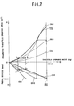
- Fig. 7 is a graphical representation for, assistance in explaining the method of obtaining the relationship between the accelerator pedal stroke S and the .throttle valve opening rate ⁇ (CB2, CB3, or CB4) corresponding to the above control curves (CA2, CA3, or CA4).
- a line m is drawn in parallel with the abscissa passing through a point of inflection a of the dashed curve CA2 to obtain a point b of intersection of the line m and the solid curve CA1;
- another line n is drawn in parallel with the ordinate passing through a point of inflection a of the dashed curve CA2 to obtain a point c of intersection of the line n and the solid line CB1;
- another line p is drawn in parallel with the ordinate passing through the point b and the other line q is drawn in parallel with the abscissa passing through the point c to obtain a point d of intersection of the lines p and q.
- the point d thus obtained is to be located on a curve CB2 representative of the relationship between the accelerator pedal stroke S and the throttle valve opening rate ⁇ , which corresponds to the characteristic curve CA2.
- a plurality of points to be located on the curve CB2 can be obtained. By connecting these points, the curve CB2 can be represented.
- accelerator pedal control characteristics CB1, CB2, CB3, and CB4 thus obtained and shown in Fig. 7 are stored in a memory unit of the microcomputer 14 in the form of table data as listed below, for instance.
- the driver selects one of a plurality of accelerator pedal control characteristics determined by the curves CBl, CB2, CB3 and CB4 shown in Fig. 7, for instance, by depressing one of a plurality of control mode selector switches 10.
- a control mode selection command signal from the control mode selector switch 10 is read by the microcomputer 14 (in. block 1).
- the microcomputer 14 selects a reference table (e.g.
- the microcomputer 14 receives the current accelerator pedal stroke (e.g. ps2) detected by the pedal potentiometer 11 via the A-D converter 13 (in block 3).
- a target throttle valve opening rate e.g. e 21
- a target throttle valve opening rate is calculated or corrected under consideration of other engine operating conditions, where necessary (in block 4).
- the target throttle' valve opening rate is outputted from the microcomputer 14 to activate the servomotor driver circuit 16.
- the servomotor 17 is feedback-controlled to set the throttle valve to the target throttle valve opening rate (in block 5 ).
- the above control steps from blocks 1 to 5 are so repeatedly implemented that the accelerator pedal control characteristic CB1 selected by the driver may be attained by detecting the magnitude of the accelerator pedal stroke by the pedal potentiometer 11.
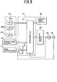
- Fig. 9 shows a second embodiment of the accelerator pedal control system for an automotive vehicle according to the present invention.
- the accelerator pedal control characteristics can freely be modified by driver's preference for each selected control mode and further a stepmotor is used for driving the throttle value, in place of the servomotor.
- the accelerator pedal control system comprises, in particular, a control characteristic entry section 20 on the input side of the microcomputer 14, in addition to a control mode selector switch 10, a pedal potentiometer 11 and an analog-to-digital converter 13.
- control characteristic entry section 20 there are provided a plurality of potentiometers 20a, 20b,...20n corresponding to the predetermined number n of divided accelerator pedal stroke steps (e.g. six steps), by which it is possible to preset any desired throttle valve opening rates 6 at the predetermined pedal strokes S according to driver's preference, for each control mode.
- n of divided accelerator pedal stroke steps e.g. six steps
- control mode selector switch 10 selects, when depressed, one of a plurality of previously stored control characteristics modified by. driver's preference; the accelerator pedal potentiometer 11 detects the stroke of the accelerator pedal, the analog-to-digital converter 13 converts an analog pedal potentiometer signal into a digital signal corresponding thereto.
- the accelerator pedal control system comprises, in particular, a stepmotor driver circuit 22 and a stepmotor 24 on the output side of the microcomputer 14 in place of the servomotor driver circuit and the servomotor. Since the stepmotor 24 is incorporated with the system, it is possible to eliminate the use of a digital-to-analog converter used for the first embodiment shown in Fig. 3.
- the retrieved target throttle valve opening rate is directly outputted as a throttle valve control signal to the stepmotor driver circuit 22.
- the stepmotor driver circuit 22 actuates the stepmotor 24 for driving the throttle valve to the target opening rate.
- the Opening rate of the throttle valve is detected by the valve potentiometer 18 and is feedbacked to the microcomputer 14 via the analog-to-digital converter 13.
- the feedback signal from the valve potentiometer 18 is not applied to the stepmotor driver circuit 22 but to the microcomputer 14 via the analog-to-digital converter l3.
- the digital signal outputted from the stepmotor driver 22 is also feedbacked to the microcomputer 14 directly for checking the number of pulses.
- the microcomputer 14 must detect the difference between the target revolution angle and the current stepwise revolution angle of the stepmotor in the normal or reverse direction and output an appropriate control signal to the stepmotor driver circuit 22 in digital control fashion. That is to say, the microcomputer 14 feedback-controls the throttle valve by means of the stepmotor driver circuit 22, the stepmotor 24 and the valve potentiometer 18 in response to the signal indicative of target throttle valve opening rate from the microcomputer 14 and the feedback signal indicative of throttle valve revolution angle, so that the throttle valve reaches the target opening rate.
- the selected throttle valve control mode is displayed on the selected mode display 19 in an appropriate method optically and numerically or pictorially.
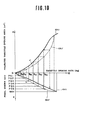
- Fig. 10 With reference to Fig. 10, the method of presetting the throttle valve opening rates corresponding to each pedal stroke through the control characteristic entry section 20 on the basis of driver's preference will be described hereinbelow.
- Fig. 10 a case is represented where six potentiometers are provided for presetting six throttle valve opening rates at six different accelerator pedal strokes psl to ps6 by way of example.
- a basic control characteristic can be represented by the curve CB1 where the throttle valve opening rate ⁇ increases linearly with increasing accelerator pedal stroke S and by the curve CAl where the projected throttle valve opening area A increases with increasing throttle valve opening rate 9.
- the driver can freely preset any desired basic characteristic by his preference as shown by the curves CAl' and CB1' of Fig. 10, for instance, by adjusting the six potentiometers 20a...20f, independently, according to pedal strokes psl...ps6.
- Fig. 10 shows the case where the relationship between S and e is determined as listed in table 2 below:
- the first potentiometer 20a corresponding to the first stroke psl is adjusted to ⁇ 10 ; the second potentiometer 20b corresponding to the second stroke ps2 is adjusted to ⁇ 20 ; being repeated in like manner.
- the first adjusted throttle valve opening rate value 8 10 is stored in a first address of the memory section of the microcomputer; the second adjusted value ⁇ 20 is stored in a second address of the memory section; being repeated in like manner.
- a control mode selection command signal from the mode selector switch 10 is read by the microcomputer.
- the 5 microcomputer 14 selects the reference table 2 of modified throttle valve opening rates ⁇ 10 , ⁇ 20 , ⁇ 60 .
- the microcomputer 14 reads the first accelerator pedal stroke psl detected by the pedal potentiometer 11, the first throttle valve opening rate e corresponding to the first stroke psl is retrieved from the selected reference table 2 and the first target throttle valve opening rate ⁇ 10 is calculated and corrected to activate the stepmotor 22, so that the throttle valve 6 is opened to the target throttle valve opening rate.
- the microcomputer 14 reads the second accelerator pedal stroke ps2, the second throttle valve opening rate ⁇ 20 corresponding to ps2 is reetrieved from the selected reference table 2 to calculate the second target throttle valve opening rate, being repeated in like manner.
- the horizontal and vertical dashed lines indicate the method of obtaining the relationship CB1' between the accelerator pedal stroke S and the throttle valve opening rate 9, which corresponds to the curves CAll, as already explained in great detail with reference to Fig. 7.
- the accelerator pedal control system according to the present invention has been described of the case when the system is applied to a one-barrel throttle device by way of example. However, it is of course possible to apply this system according to the present invention to a two-barrel throttle device. Further, potentiometers have been adopted for detecting the stroke of the accelerator pedal and the revolution angle of the throttle valve by way of example. However, without being limited to these analog detecting means, it is of course possible to adopt a pulse sensor which outputs a pulse signal for each unit displacement of the pedal stroke or valve opening angle and a counter for counting the number of pulse signals outputted from the pulse sensor, that is, in digital detection fashion.
- the number of selectable accelerator pedal control characteristics is four of C B1 , CB2, CB3 and CB4 in the first embodiment shown in Fig. 3 and the number of the presettable accelerator pedal strokes is six of psl, ps2,. ps3, ps4, ps5 and ps6 in the second embodiment shown in Fig. 9.
- the number of selectable accelerator pedal control characteristics is four of C B1 , CB2, CB3 and CB4 in the first embodiment shown in Fig. 3
- the number of the presettable accelerator pedal strokes is six of psl, ps2,. ps3, ps4, ps5 and ps6 in the second embodiment shown in Fig. 9.
- the accelerator pedal control system for an automotive vehicle since a plurality of different accelerator pedal control characteristics representative of relationship between accelerator pedal stroke S and throttle valve opening rate e are previously stored and since any desired control characteristic can be selected by depressing one of control mode selector switch freely by driver's preference, it is possible to accelerate the vehicle in accordance with a desired accelerator pedal control characteristic by driver's preference or according to vehicle travelling conditions. For instance, when the vehicle is travelling at a relatively low speed on a busy street and the accelerator pedal and the brake pedal are both repeatedly depressed alternately, an appropriate control characteristic such as CB4 on which the throttle valve opening rate increases relatively gently with increasing accelerator pedal stroke can be selected, thus the low-speed operability of the accelerator pedal being improved.
- an appropriate control characteristic such as CB4 on which the throttle valve opening rate increases relatively gently with increasing accelerator pedal stroke
- accelerator pedal control characteristics can be modified freely by driver's preference by adjusting the potentiometers in the second embodiment, it is possible to provide more appropriate accelerator pedal control characteristics for the driver.
Applications Claiming Priority (2)
| Application Number | Priority Date | Filing Date | Title |
|---|---|---|---|
| JP18206682A JPS5974341A (ja) | 1982-10-19 | 1982-10-19 | 車両用アクセル制御装置 |
| JP182066/82 | 1982-10-19 |
Publications (2)
| Publication Number | Publication Date |
|---|---|
| EP0106360A2 true EP0106360A2 (fr) | 1984-04-25 |
| EP0106360A3 EP0106360A3 (fr) | 1984-09-05 |
Family
ID=16111748
Family Applications (1)
| Application Number | Title | Priority Date | Filing Date |
|---|---|---|---|
| EP83110385A Withdrawn EP0106360A3 (fr) | 1982-10-19 | 1983-10-18 | Système de commande de la pédale d'accélérateur pour véhicule automobile |
Country Status (2)
| Country | Link |
|---|---|
| EP (1) | EP0106360A3 (fr) |
| JP (1) | JPS5974341A (fr) |
Cited By (15)
| Publication number | Priority date | Publication date | Assignee | Title |
|---|---|---|---|---|
| DE3417089A1 (de) * | 1984-05-09 | 1985-11-14 | Robert Bosch Gmbh, 7000 Stuttgart | Vortriebsregeleinrichtung |
| EP0189190A2 (fr) * | 1985-01-24 | 1986-07-30 | Mazda Motor Corporation | Système de commande de papillon d'accélérateur de moteur à combustion interne |
| EP0203529A2 (fr) * | 1985-05-27 | 1986-12-03 | Nissan Motor Co., Ltd. | Système et méthode de commande de l'ouverture du papillon en fonction de la position de la pédale d'accélérateur d'un véhicule automobile |
| EP0230745A2 (fr) * | 1985-12-19 | 1987-08-05 | Nippondenso Co., Ltd. | Système de commande d'accélération de véhicule |
| EP0121937B1 (fr) * | 1983-04-11 | 1987-08-12 | Nissan Motor Co., Ltd. | Système de commande d'une pédale de gaz d'un véhicule motorisé |
| GB2218465A (en) * | 1988-05-14 | 1989-11-15 | Ford Motor Co | I.C. engine ignition system |
| EP0581289A1 (fr) * | 1992-07-30 | 1994-02-02 | Sumitomo Electric Industries, Limited | Dispositif et procédé de réglage électronique d'une pédale de frein |
| GB2335056A (en) * | 1998-03-02 | 1999-09-08 | Cummins Engine Co Inc | Throttle control response selection method and apparatus |
| EP2161433A2 (fr) | 2008-09-05 | 2010-03-10 | Yamaha Hatsudoki Kabushiki Kaisha | Dispositif de commande de papillon et véhicule équipé de celui-ci |
| US8076062B2 (en) | 2002-07-01 | 2011-12-13 | Tibotec Pharmaceuticals Ltd. | Mutational profiles in HIV-1 protease correlated with phenotypic drug resistance |
| CN108760343A (zh) * | 2018-07-13 | 2018-11-06 | 吉林大学 | 基于油门踏板自动控制的发动机转速调节装置及调节方法 |
| CN112389196A (zh) * | 2019-08-19 | 2021-02-23 | 北京新能源汽车股份有限公司 | 一种踏板信号的修正方法、装置及汽车 |
| CN112983654A (zh) * | 2019-12-13 | 2021-06-18 | 丰田自动车株式会社 | 控制系统 |
| CN113525398A (zh) * | 2020-04-13 | 2021-10-22 | 北京罗克维尔斯科技有限公司 | 一种车辆油门开度调整方法及装置 |
| CN114753935A (zh) * | 2022-04-24 | 2022-07-15 | 殷国明 | 一种汽车油门自动加速控制系统 |
Families Citing this family (10)
| Publication number | Priority date | Publication date | Assignee | Title |
|---|---|---|---|---|
| JPS6183470A (ja) * | 1984-09-29 | 1986-04-28 | Mazda Motor Corp | エンジンのスロツトル弁制御装置 |
| JPH0610429B2 (ja) * | 1985-01-24 | 1994-02-09 | マツダ株式会社 | エンジンのスロットル弁制御装置 |
| JPS61283740A (ja) * | 1985-06-10 | 1986-12-13 | Isuzu Motors Ltd | エンジンの燃料供給量制御装置 |
| JPS6255430A (ja) * | 1985-09-02 | 1987-03-11 | Mazda Motor Corp | エンジンのスロツトル弁制御装置 |
| JP2564275B2 (ja) * | 1986-05-09 | 1996-12-18 | 株式会社日立製作所 | 状態適応型内燃機関制御システム |
| JPS63109254A (ja) * | 1986-10-27 | 1988-05-13 | Mazda Motor Corp | エンジンの制御装置 |
| JPS63219858A (ja) * | 1987-03-09 | 1988-09-13 | Nissan Koki Kk | 電子ガバナ−における制御方法 |
| JP2896142B2 (ja) * | 1988-02-18 | 1999-05-31 | ヤマハ発動機株式会社 | 車輌のスロットル制御装置 |
| JP4818337B2 (ja) | 2008-09-17 | 2011-11-16 | 本田技研工業株式会社 | 車両の制御装置 |
| US10138818B2 (en) | 2012-09-04 | 2018-11-27 | Honda Motor Co., Ltd. | Internal combustion engine control system |
Citations (6)
| Publication number | Priority date | Publication date | Assignee | Title |
|---|---|---|---|---|
| FR2356007A1 (fr) * | 1976-06-24 | 1978-01-20 | Henry Jancelin Georges | Dispositif de servo-commande electronique de l'admission des gaz dans les moteurs a explosion |
| DE2751125A1 (de) * | 1977-11-16 | 1979-05-17 | Bosch Gmbh Robert | Steuereinrichtung fuer eine brennkraftmaschine |
| FR2435369A1 (fr) * | 1978-09-11 | 1980-04-04 | Vdo Schindling | Appareil destine a transmettre la position d'un element de commande actionne par le conducteur d'un vehicule automobile et regulant la vitesse de marche de celui-ci |
| FR2437953A1 (fr) * | 1978-10-05 | 1980-04-30 | Vdo Schindling | Appareil destine a reguler la vitesse de marche d'un vehicule automobile |
| DE2926106A1 (de) * | 1979-06-28 | 1981-01-08 | Volkswagenwerk Ag | Verfahren und anordnung zum betrieb einer fahrzeug-brennkraftmaschine |
| FR2483012A1 (fr) * | 1980-05-22 | 1981-11-27 | Daimler Benz Ag | Dispositif de commande d'un moteur a combustion interne |
-
1982
- 1982-10-19 JP JP18206682A patent/JPS5974341A/ja active Pending
-
1983
- 1983-10-18 EP EP83110385A patent/EP0106360A3/fr not_active Withdrawn
Patent Citations (6)
| Publication number | Priority date | Publication date | Assignee | Title |
|---|---|---|---|---|
| FR2356007A1 (fr) * | 1976-06-24 | 1978-01-20 | Henry Jancelin Georges | Dispositif de servo-commande electronique de l'admission des gaz dans les moteurs a explosion |
| DE2751125A1 (de) * | 1977-11-16 | 1979-05-17 | Bosch Gmbh Robert | Steuereinrichtung fuer eine brennkraftmaschine |
| FR2435369A1 (fr) * | 1978-09-11 | 1980-04-04 | Vdo Schindling | Appareil destine a transmettre la position d'un element de commande actionne par le conducteur d'un vehicule automobile et regulant la vitesse de marche de celui-ci |
| FR2437953A1 (fr) * | 1978-10-05 | 1980-04-30 | Vdo Schindling | Appareil destine a reguler la vitesse de marche d'un vehicule automobile |
| DE2926106A1 (de) * | 1979-06-28 | 1981-01-08 | Volkswagenwerk Ag | Verfahren und anordnung zum betrieb einer fahrzeug-brennkraftmaschine |
| FR2483012A1 (fr) * | 1980-05-22 | 1981-11-27 | Daimler Benz Ag | Dispositif de commande d'un moteur a combustion interne |
Non-Patent Citations (2)
| Title |
|---|
| AUTOMOTIVE ENGINEERING; vol. 90, no. 6, June 1982, pages 97-99, Dallas, Texas, US; "Electronic accelerators have economy functions". * |
| MTZ - MOTORTECHNISCHE ZEITSCHRIFT, vol. 42, no. 12, December 1981, page 528, Schw{bisch-Gm}nd, DE; "Elektronisches Gaspedal von Bosch". * |
Cited By (26)
| Publication number | Priority date | Publication date | Assignee | Title |
|---|---|---|---|---|
| EP0121937B1 (fr) * | 1983-04-11 | 1987-08-12 | Nissan Motor Co., Ltd. | Système de commande d'une pédale de gaz d'un véhicule motorisé |
| DE3417089A1 (de) * | 1984-05-09 | 1985-11-14 | Robert Bosch Gmbh, 7000 Stuttgart | Vortriebsregeleinrichtung |
| EP0163940A1 (fr) * | 1984-05-09 | 1985-12-11 | Robert Bosch Gmbh | Système régulateur de la propulsion |
| US4771849A (en) * | 1984-05-09 | 1988-09-20 | Robert Bosch Gmbh | System for controlling the fuel supplied to an automotive engine |
| EP0189190A2 (fr) * | 1985-01-24 | 1986-07-30 | Mazda Motor Corporation | Système de commande de papillon d'accélérateur de moteur à combustion interne |
| EP0189190A3 (en) * | 1985-01-24 | 1987-12-09 | Mazda Motor Corporation | Throttle valve control system for internal combustion engine |
| EP0203529A2 (fr) * | 1985-05-27 | 1986-12-03 | Nissan Motor Co., Ltd. | Système et méthode de commande de l'ouverture du papillon en fonction de la position de la pédale d'accélérateur d'un véhicule automobile |
| EP0203529A3 (en) * | 1985-05-27 | 1988-03-16 | Nissan Motor Co., Ltd. | A system and method for controlling the opening angle of a throttle valve according to the position of an accelerator for an automotive vehicle |
| EP0230745A2 (fr) * | 1985-12-19 | 1987-08-05 | Nippondenso Co., Ltd. | Système de commande d'accélération de véhicule |
| EP0230745A3 (en) * | 1985-12-19 | 1988-10-19 | Nippondenso Co., Ltd. | Vehicle acceleration control system vehicle acceleration control system |
| GB2218465A (en) * | 1988-05-14 | 1989-11-15 | Ford Motor Co | I.C. engine ignition system |
| US5378052A (en) * | 1992-07-30 | 1995-01-03 | Sumitomo Electric Industries, Ltd. | Electronic brake pedal adjustment apparatus and method therefor |
| EP0581289A1 (fr) * | 1992-07-30 | 1994-02-02 | Sumitomo Electric Industries, Limited | Dispositif et procédé de réglage électronique d'une pédale de frein |
| GB2335056A (en) * | 1998-03-02 | 1999-09-08 | Cummins Engine Co Inc | Throttle control response selection method and apparatus |
| US6085725A (en) * | 1998-03-02 | 2000-07-11 | Cummins Engine Co., Inc. | Throttle control response selection system |
| GB2335056B (en) * | 1998-03-02 | 2002-05-01 | Cummins Engine Co Inc | Throttle control response selecton method and apparatus |
| US8076062B2 (en) | 2002-07-01 | 2011-12-13 | Tibotec Pharmaceuticals Ltd. | Mutational profiles in HIV-1 protease correlated with phenotypic drug resistance |
| EP2161433A3 (fr) * | 2008-09-05 | 2010-04-21 | Yamaha Hatsudoki Kabushiki Kaisha | Dispositif de commande de papillon et véhicule équipé de celui-ci |
| EP2161433A2 (fr) | 2008-09-05 | 2010-03-10 | Yamaha Hatsudoki Kabushiki Kaisha | Dispositif de commande de papillon et véhicule équipé de celui-ci |
| US8516992B2 (en) | 2008-09-05 | 2013-08-27 | Yamaha Hatsudoki Kabushiki Kaisha | Throttle control device and vehicle equipped with the same |
| CN108760343A (zh) * | 2018-07-13 | 2018-11-06 | 吉林大学 | 基于油门踏板自动控制的发动机转速调节装置及调节方法 |
| CN112389196A (zh) * | 2019-08-19 | 2021-02-23 | 北京新能源汽车股份有限公司 | 一种踏板信号的修正方法、装置及汽车 |
| CN112983654A (zh) * | 2019-12-13 | 2021-06-18 | 丰田自动车株式会社 | 控制系统 |
| CN113525398A (zh) * | 2020-04-13 | 2021-10-22 | 北京罗克维尔斯科技有限公司 | 一种车辆油门开度调整方法及装置 |
| CN113525398B (zh) * | 2020-04-13 | 2022-07-15 | 北京罗克维尔斯科技有限公司 | 一种车辆油门开度调整方法及装置 |
| CN114753935A (zh) * | 2022-04-24 | 2022-07-15 | 殷国明 | 一种汽车油门自动加速控制系统 |
Also Published As
| Publication number | Publication date |
|---|---|
| EP0106360A3 (fr) | 1984-09-05 |
| JPS5974341A (ja) | 1984-04-26 |
Similar Documents
| Publication | Publication Date | Title |
|---|---|---|
| EP0106360A2 (fr) | Système de commande de la pédale d'accélérateur pour véhicule automobile | |
| EP0114401B1 (fr) | Système de commande d'accélérateur pour véhicule automobile | |
| JP4242406B2 (ja) | スロットル制御応答選択方法 | |
| US4691676A (en) | Apparatus for throttle valve control | |
| US5078109A (en) | Engine output controlling method | |
| US4519360A (en) | Accelerator pedal control system for automotive vehicle | |
| US5389051A (en) | Method of and apparatus for controlling engine speed of a vehicle engine | |
| US4750598A (en) | Control system for the throttle valve of a vehicle engine | |
| US5521825A (en) | Engine inlet air valve positioning | |
| US4884203A (en) | Method for influencing the driving speed of a motor vehicle and apparatus therefor | |
| EP0003592A1 (fr) | Dispositif de commande automatique d'une boîte de vitesses | |
| EP0121939A1 (fr) | Système de commande du papillon d'un véhicule motorisé | |
| CN1080656C (zh) | 离合器控制系统 | |
| US5845726A (en) | Vehicle driving force control apparatus | |
| JPH0475416B2 (fr) | ||
| EP0203529A2 (fr) | Système et méthode de commande de l'ouverture du papillon en fonction de la position de la pédale d'accélérateur d'un véhicule automobile | |
| US5957992A (en) | Vehicle cruise control system and method having improved target speed resolution feature | |
| US4461254A (en) | Device for controlling the position of an element which controls the fuel-air mixture | |
| US4586403A (en) | Adaptively calibrated sensing mechanism for an engine demand device | |
| US6026783A (en) | Device and method for calibration of a throttle arrangement | |
| US4893243A (en) | Control device for maintaining constant speed of an automobile | |
| EP0265526A1 (fr) | Dispositif regulateur du moteur d'un engin de terrassement muni de roues | |
| EP0080362A1 (fr) | Dispositif de limitation de vitesse d'un moteur et/ou d'un véhicule | |
| US5871417A (en) | Continuously variable transmission control apparatus | |
| US4843555A (en) | Signal processing system for vehicular acceleration sensor |
Legal Events
| Date | Code | Title | Description |
|---|---|---|---|
| PUAI | Public reference made under article 153(3) epc to a published international application that has entered the european phase |
Free format text: ORIGINAL CODE: 0009012 |
|
| 17P | Request for examination filed |
Effective date: 19831018 |
|
| AK | Designated contracting states |
Designated state(s): DE FR GB |
|
| PUAL | Search report despatched |
Free format text: ORIGINAL CODE: 0009013 |
|
| AK | Designated contracting states |
Designated state(s): DE FR GB |
|
| RAP1 | Party data changed (applicant data changed or rights of an application transferred) |
Owner name: NISSAN MOTOR CO., LTD. |
|
| STAA | Information on the status of an ep patent application or granted ep patent |
Free format text: STATUS: THE APPLICATION IS DEEMED TO BE WITHDRAWN |
|
| 18D | Application deemed to be withdrawn |
Effective date: 19860221 |
|
| RIN1 | Information on inventor provided before grant (corrected) |
Inventor name: MURAKAMI, TERUKIYO |