EP0188694A2 - Procédé et dispositif pour la registration photographique de véhicules - Google Patents
Procédé et dispositif pour la registration photographique de véhicules Download PDFInfo
- Publication number
- EP0188694A2 EP0188694A2 EP85114741A EP85114741A EP0188694A2 EP 0188694 A2 EP0188694 A2 EP 0188694A2 EP 85114741 A EP85114741 A EP 85114741A EP 85114741 A EP85114741 A EP 85114741A EP 0188694 A2 EP0188694 A2 EP 0188694A2
- Authority
- EP
- European Patent Office
- Prior art keywords
- speed
- measuring
- vehicle
- value
- doppler
- Prior art date
- Legal status (The legal status is an assumption and is not a legal conclusion. Google has not performed a legal analysis and makes no representation as to the accuracy of the status listed.)
- Granted
Links
Images
Classifications
-
- G—PHYSICS
- G01—MEASURING; TESTING
- G01S—RADIO DIRECTION-FINDING; RADIO NAVIGATION; DETERMINING DISTANCE OR VELOCITY BY USE OF RADIO WAVES; LOCATING OR PRESENCE-DETECTING BY USE OF THE REFLECTION OR RERADIATION OF RADIO WAVES; ANALOGOUS ARRANGEMENTS USING OTHER WAVES
- G01S13/00—Systems using the reflection or reradiation of radio waves, e.g. radar systems; Analogous systems using reflection or reradiation of waves whose nature or wavelength is irrelevant or unspecified
- G01S13/88—Radar or analogous systems specially adapted for specific applications
- G01S13/91—Radar or analogous systems specially adapted for specific applications for traffic control
- G01S13/92—Radar or analogous systems specially adapted for specific applications for traffic control for velocity measurement
-
- G—PHYSICS
- G08—SIGNALLING
- G08G—TRAFFIC CONTROL SYSTEMS
- G08G1/00—Traffic control systems for road vehicles
- G08G1/01—Detecting movement of traffic to be counted or controlled
- G08G1/052—Detecting movement of traffic to be counted or controlled with provision for determining speed or overspeed
- G08G1/054—Detecting movement of traffic to be counted or controlled with provision for determining speed or overspeed photographing overspeeding vehicles
Definitions
- the invention relates to a method for the pictorial, in particular photographic registration of oncoming vehicles by means of a Doppler radar speed measuring device equipped with an image recording device, with which the vehicles are measured from the front and registered visually, during a measuring section after a vehicle has entered the measuring lobe determines a corresponding speed measurement value, and then, if this exceeds a certain limit value, the image recording device is triggered, and the speed measurement value is superimposed on the recording.
- a method for triggering the camera in a Doppler radar speed measuring device in which the vehicles are measured and photographed from behind, the triggering of the camera being suppressed if the measured speed value is not without doubt a specific vehicle can be assigned.
- the system becomes more expensive due to the use of two cameras and it also becomes unwieldy and should only be suitable for stationary, but not for mobile use.
- the object of the invention is now to increase the measurement reliability for the measurement arrangement and photography from the front, that is to say oncoming traffic, which is preferred today, and to eliminate the recordings which cannot be evaluated, or at least to drastically reduce their number.
- the object is achieved according to the invention in that after the triggering of the image recording device, the Doppler signal generated when the vehicle travels through a section of the measuring lobe referred to below as the verification route, and the result of this evaluation is used to check the speed measurement value.
- the method according to the invention thus enables the evaluation of the entire Doppler signal generated during the passage through the measuring lobe by checking the original measured speed value via the verification route. In particular, overtaking processes in the area of the measuring lobe can also be recorded.
- the invention further relates to a device for carrying out the above-mentioned method, with a Doppler radar speed measuring device, with a computer for evaluating the Doppler signals and with a camera having a data display unit, which is triggered by the computer with a camera trigger Film transport and a data insertion signal is driven.
- the device according to the invention is characterized in that, after the camera trigger signal has been given, the computer checks the speed measurement value of the appropriate vehicle via the verification route and, based on the result of this check, either triggers the display of the speed measurement value or the cancellation of the measurement and then triggers the further transport of the film.
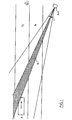
- the vehicle F As soon as the vehicle F enters the measuring lobe M with its front, as shown in the figure, it reflects the radar radiation and, in a known manner, an electrical oscillation, the Doppler signal, is generated in the radar device by superimposing a portion of the transmission energy on the reception energy reflected by the vehicle whose frequency, the Doppler frequency is proportional to the relative speed between the vehicle and the radar.
- a speed measurement value is determined from the average of the Doppler frequency stable during this measuring section and similar to the method described in DE-PS 1 805 903 saved. As soon as this exceeds a stored speed limit for the maximum speed permitted at the measurement location, the camera is triggered and the vehicle is photographed from the front; however, the film will not be transported further.
- the Doppler frequency is then checked for its temporal behavior in comparison to the previously stored speed measurement value. For this purpose, a tolerance range of, for example, ⁇ 3%, based on this stored speed measurement value, is first determined and time values are calculated from the speed measurement value, which correspond to certain route lengths which the vehicle F travels.
- a section of the route, the so-called verification section of, for example, a length of 3 m is defined, within which the Doppler frequency must not show any significant deviations from the stored speed measurement value.
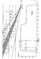
- a significant deviation is defined as an uninterrupted leaving of the tolerance range during a distance exceeding a certain limit length of, for example, 1 m.
- exceeding or falling below the tolerance range as can occur with every measurement even without the presence of other vehicles in the measuring lobe, are tolerated and therefore do not lead to a cancellation of the measurement.
- the vehicle F 1 enters the measuring lobe M at a higher speed than the vehicle F 2 . Therefore, the Doppler frequency soon leaves the tolerance range C, and not just temporarily, but over the entire remaining length of the verification path B. A significant deviation of the Doppler frequency from the stored speed measurement value is therefore found within the verification path B. Therefore, after the end of the verification route at time t 6, a cancellation sign is superimposed on the picture already taken and the film is then transported on. On the picture you will be able to see the two vehicles F 1 and F 2 , whose mutual distance is so small that it is not possible to assign measured values.
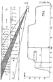
- two vehicles F 1 and F 2 drive into the measuring lobe M at the same time t 1, namely the vehicle F 1 at a speed of approximately 90 km / h and the vehicle F 2 at such a speed about 60 km / h.
- the vehicle F 1 completely covers the vehicle F 2 , so that the Doppler frequency increases immediately to the value for the vehicle F 1 and remains at this value until the rear of the vehicle F 1 leaves the measuring lobe M shortly after the time t 8 .
- the Doppler frequency adopts a value corresponding to the speed of the slower vehicle F 2 , but this does not prevent the successful measurement and registration of the vehicle F 1 on the track S 1 .
- the Doppler frequency reaches a value at the time t from which it does not deviate significantly until the time t b at which the measurement section A is ended, so that a reliable speed measurement value can be formed during the measurement section A on the basis of the average value.
- a tolerance range C With this measured value, a tolerance range C, the length of a significant deviation and the length of the verification distance B are now determined and the camera is also triggered at time t b after the determination of the speed measured value, but the film has not yet been transported. Since the speed measurement value is greater than in the example of FIG. 2, the tolerance range C is also greater and the time in which the measurement and verification sections A and B are traveled is correspondingly shorter.
- the recording can also be evaluated correctly, although two vehicles F 1 and F 2 can be seen on it.
- the fact that a speed measurement value and no cancellation display is shown proves that the rear vehicle F 2 did not appear significantly during the measurement. Because if the vehicle F 2 had driven faster, it would have influenced the Doppler frequency during the verification route and significant deviations would have occurred, so that a cancellation display would have been shown.
- FIGS. 2 and 3 are merely examples to explain the functioning and mode of operation of the method according to the invention. Of course, many other traffic situations are conceivable in which the method according to the invention can also be used in a particularly useful manner.
- the terms camera and film used in the description are not to be understood in such a way that the described method would be restricted to photographic films and cameras that are common today; rather, they refer to every conceivable recording and registration device and every suitable medium. For example, you could also use electronic video cameras and magnetic tapes or diskettes.
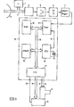
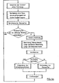
- a microwave oscillator 1 generates a microwave signal which is fed to an antenna 3 via a waveguide 2 and radiated by the latter. As soon as a vehicle travels through the radiation area of the antenna 3, these radiation components are reflected to the antenna 3. These reflected radiation components are shifted by an amount which is proportional to the speed of the vehicle compared to those originally emitted by the antenna 3. This phenomenon is called the Doppler effect and the frequency shift is called the Doppler frequency.
- the reflected radiation components received by the antenna 3 are fed via the waveguide 2 to a mixer 4, to which a small part of the original microwave signal generated by the microwave oscillator also reaches.
- the two signals mentioned are mixed in the mixer 4 and the resulting mixed product, a low-frequency AC voltage with the Doppler frequency, is applied to the input of a Amplifier 5 placed.
- Its output signal is fed to the input of a filter 6, which is only permeable to the part of the spectrum that is of interest for further evaluation, that is, the Doppler spectral component belonging to the speed measurement range of the radar device. This eliminates the components of the noise voltage outside the pass band of the filter 6, so that the signal-to-noise ratio is improved.
- the signal appearing at the output of the filter 6 is then digitized by a Schmitt trigger 7.
- the digital signal which can be taken off at the output of the Schmitt trigger 7 contains all useful information about the speed of the objects moving in the radar beam. It is led to the input of a timer 11 (e.g. INTEL 8253) belonging to a microcomputer 10, in which the time intervals between the logical changes in the digitized Doppler signal are measured sequentially and are offered to the microcomputer 11 for evaluation.
- the microcomputer also contains a central processing unit (CPU) 12 (e.g. INTEL 8085) with a crystal 13, which outputs a clock signal to the timer 11 via a line 14, an erasable, programmable read-only memory (EPROM) 15 (e.g.
- INTEL 2764 a data memory with random access (RAM) 16 (e.g. INTEL 8185) and an input / output stage (I / 0) 17 (e.g. INTEL 8255), all of which are connected by a busbar 18 for the transfer of data, addresses and control signals .
- RAM random access
- I / 0 input / output stage
- a registration camera K with a data insertion device D is controlled via the input / output stage 17.
- the camera K is via lines 8 and 9 for the camera release or film transport signal and the data insertion device D is by means of a busbar 19 for the data to be inserted and a line 20 for the data insertion signal with the input / output stage 17 connected.
- the data memory 16 is used for temporary Storage of variable data and intermediate results and the programmable read-only memory 15 contains the program of the microcomputer 10 in binary code.
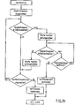
- the verification is shown separately in FIG. 5b: At the beginning of the verification, a counter contained in the timer 11 (FIG. 4) which is to measure the elapsed length of the verification route is started. It is then checked whether the last measured Doppler period is within the fixed tolerance range. If this is the case, the route length counter is then queried as to whether the verification route has already expired. If this is not the case, the next Doppler period is checked to determine whether it is within the tolerance range. If this is also within the tolerance range, the route length counter is queried again, and so on. If the Doppler frequency remains within the tolerance range over the entire verification path, then the verification is successfully completed at the end of this path and a return is made to the main program (FIG. 5a).
- an outlier length counter contained in the timer 11 (FIG. 4) is first started, which counts the length of the "outlier" just detected, i.e. measure the time period during which the Doppler frequency is outside the tolerance range. The length of the next Doppler period is then measured. If this is also outside the tolerance range, the outlier length counter is queried. If the current outlier has not yet reached the length of a significant deviation, the length of the next Doppler period is measured.
- the speed measurement value is transmitted to the data insertion device D (FIG. 4) and the insertion signal is output.
- the cancellation symbol - is transmitted to the data insertion device and the insertion signal is likewise output.
- the film transport signal is emitted to the camera K (FIG. 4) and the detection of the entrance of the next vehicle is then awaited.
Landscapes
- Physics & Mathematics (AREA)
- Engineering & Computer Science (AREA)
- Radar, Positioning & Navigation (AREA)
- Remote Sensing (AREA)
- General Physics & Mathematics (AREA)
- Electromagnetism (AREA)
- Computer Networks & Wireless Communication (AREA)
- Traffic Control Systems (AREA)
- Radar Systems Or Details Thereof (AREA)
- Automobile Manufacture Line, Endless Track Vehicle, Trailer (AREA)
Priority Applications (1)
| Application Number | Priority Date | Filing Date | Title |
|---|---|---|---|
| AT85114741T ATE57033T1 (de) | 1984-11-30 | 1985-11-19 | Verfahren und vorrichtung zur photographischen registrierung von fahrzeugen. |
Applications Claiming Priority (2)
| Application Number | Priority Date | Filing Date | Title |
|---|---|---|---|
| CH5721/84A CH662660A5 (de) | 1984-11-30 | 1984-11-30 | Verfahren und vorrichtung zur bildlichen, insbesondere photographischen registrierung von entgegenkommenden fahrzeugen. |
| CH5721/84 | 1984-11-30 |
Publications (3)
| Publication Number | Publication Date |
|---|---|
| EP0188694A2 true EP0188694A2 (fr) | 1986-07-30 |
| EP0188694A3 EP0188694A3 (en) | 1988-03-30 |
| EP0188694B1 EP0188694B1 (fr) | 1990-09-26 |
Family
ID=4298254
Family Applications (1)
| Application Number | Title | Priority Date | Filing Date |
|---|---|---|---|
| EP85114741A Expired - Lifetime EP0188694B1 (fr) | 1984-11-30 | 1985-11-19 | Procédé et dispositif pour la registration photographique de véhicules |
Country Status (7)
| Country | Link |
|---|---|
| US (1) | US4717915A (fr) |
| EP (1) | EP0188694B1 (fr) |
| AT (1) | ATE57033T1 (fr) |
| AU (1) | AU585275B2 (fr) |
| CH (1) | CH662660A5 (fr) |
| DE (1) | DE3579907D1 (fr) |
| ES (1) | ES8705126A1 (fr) |
Cited By (9)
| Publication number | Priority date | Publication date | Assignee | Title |
|---|---|---|---|---|
| EP0286910A3 (en) * | 1987-04-11 | 1989-07-12 | Robot Foto & Electronic Gmbh & Co Kg | Traffic surveillance device |
| EP0350751A3 (fr) * | 1988-07-14 | 1990-07-18 | Multanova Ag | Procédé et appareil de surveillance de la vitesse de véhicules utilisant un radar Doppler de mesure de vitesse et application du procédé |
| DE4326398C1 (de) * | 1993-08-06 | 1994-07-21 | Leica Sensortechnik Gmbh | Verfahren und Vorrichtung zur Verkehrsüberwachung |
| FR2718874A1 (fr) * | 1994-04-15 | 1995-10-20 | Thomson Csf | Procédé de surveillance de trafic pour la détection automatique d'incident de véhicules. |
| US5912822A (en) * | 1994-06-01 | 1999-06-15 | American Traffic Systems, Inc. | Frequency domain processing of Doppler signals in a traffic monitoring system |
| US5935190A (en) * | 1994-06-01 | 1999-08-10 | American Traffic Systems, Inc. | Traffic monitoring system |
| WO2008006817A1 (fr) * | 2006-07-13 | 2008-01-17 | Siemens Aktiengesellschaft | Procédé pour la détection d'au moins un objet qui se déplace |
| EP2708902A1 (fr) * | 2012-09-12 | 2014-03-19 | Münz, Christoph | Enregistrement de vitesse symétrique et asymétrique et traitement de données décentralisé |
| EP2799903A3 (fr) * | 2013-04-30 | 2015-03-25 | Jenoptik Robot GmbH | Procédé de détection d'excès de vitesse avec un stockage de données restrictif |
Families Citing this family (18)
| Publication number | Priority date | Publication date | Assignee | Title |
|---|---|---|---|---|
| IT1221607B (it) * | 1987-08-25 | 1990-07-12 | Fiorello Sodi | Impianto per la rilevazione e la registrazione di infrazioni alle regole di disciplina stradale,con l'impiego di laser |
| DE4042494C2 (de) * | 1990-03-08 | 1998-10-29 | Conner Joe Scott O | Vorrichtung in einem Fahrzeug zur Anzeige von Relativgeschwindigkeiten zu anderen Fahrzeugen |
| DE4013037A1 (de) * | 1990-04-24 | 1991-10-31 | Standard Elektrik Lorenz Ag | Verfahren zur mobilen verkehrsueberwachung und messfahrzeug zur durchfuehrung des verfahrens |
| US5408330A (en) * | 1991-03-25 | 1995-04-18 | Crimtec Corporation | Video incident capture system |
| US6204802B1 (en) | 1991-11-15 | 2001-03-20 | O'conner Joe Scott | Apparatus for detecting relative velocity |
| DE4400624A1 (de) * | 1994-01-12 | 1995-07-13 | Conner Joe Scott O | Vorrichtung zur Geschwindigkeitsmessung von Fahrzeugen für die Verkehrsüberwachung |
| US6111523A (en) * | 1995-11-20 | 2000-08-29 | American Traffic Systems, Inc. | Method and apparatus for photographing traffic in an intersection |
| US5938717A (en) * | 1996-03-04 | 1999-08-17 | Laser Technology, Inc. | Speed detection and image capture system for moving vehicles |
| US5948038A (en) * | 1996-07-31 | 1999-09-07 | American Traffic Systems, Inc. | Traffic violation processing system |
| US6696978B2 (en) | 2001-06-12 | 2004-02-24 | Koninklijke Philips Electronics N.V. | Combined laser/radar-video speed violation detector for law enforcement |
| US7250853B2 (en) * | 2004-12-10 | 2007-07-31 | Honeywell International Inc. | Surveillance system |
| DE102007022373A1 (de) * | 2007-05-07 | 2008-11-13 | Robot Visual Systems Gmbh | Verfahren zur beweiskräftigen Erfassung der Geschwindigkeit eines Fahrzeuges |
| TW201133412A (en) * | 2010-03-19 | 2011-10-01 | Cct Co Ltd | Method of using radar vehicle detector to determine vehicle type, speed, and radar detection zone width |
| US10451727B2 (en) * | 2011-05-13 | 2019-10-22 | Amirahmad Sepehri | Method and system for detecting moving vehicle speed through athird generation photo radar |
| SI2804013T1 (sl) * | 2013-05-13 | 2015-08-31 | Kapsch Trafficcom Ag | Naprava za merjenje položaja vozila ali površine le-tega |
| PT2804014E (pt) * | 2013-05-13 | 2015-09-10 | Kapsch Trafficcom Ag | Dispositivo e método para determinar uma característica de um veículo |
| CN107219879B (zh) * | 2017-07-21 | 2022-11-25 | 电子科技大学成都学院 | 环境调节系统及温室大棚 |
| CN112598913B (zh) * | 2020-12-17 | 2022-10-04 | 多伦信息技术有限公司 | 一种基于等待因子的公交优先控制方法、装置及电子设备 |
Family Cites Families (11)
| Publication number | Priority date | Publication date | Assignee | Title |
|---|---|---|---|---|
| US3122740A (en) * | 1957-01-10 | 1964-02-25 | Admiral Corp | Velocity determining device |
| US3195126A (en) * | 1957-05-13 | 1965-07-13 | Lab For Electronics Inc | Traffic supervisory system |
| US3148015A (en) * | 1961-07-19 | 1964-09-08 | Weaver Scott | Apparatus for photographing a traffic violator |
| US3206748A (en) * | 1962-12-27 | 1965-09-14 | Miller Robert William | Vehicle speed recording apparatus |
| US3438031A (en) * | 1967-11-13 | 1969-04-08 | Duncan Parking Meter Corp | Doppler radar having digital speed indicator |
| CH470674A (de) * | 1968-02-15 | 1969-03-31 | Zellweger Uster Ag | Verfahren und Vorrichtung zur Kameraauslösung bei einer Doppler-Radar-Geschwindigkeitsmesseinrichtung |
| US3626413A (en) * | 1970-02-02 | 1971-12-07 | Howard C Zachmann | Traffic surveillance and control system |
| FR2250170A1 (en) * | 1973-11-07 | 1975-05-30 | Automatisme Cie Gle | Moving vehicle photographing device - has radar controlling a camera through a threshold circuit |
| DE2802448C2 (de) * | 1978-01-20 | 1982-03-18 | Dieter 8000 München Schwenk | Verfahren und Vorrichtung zur Herstellung von photographischen Aufnahmen von Fahrzeuginsassen |
| FR2466060A1 (fr) * | 1979-06-28 | 1981-03-27 | Sfim | Installation de controle de vitesse des vehicules automobiles |
| CH654670A5 (de) * | 1981-06-22 | 1986-02-28 | Zellweger Uster Ag | Verfahren und vorrichtung zur auswertung von signalen einer doppler-radar-geschwindigkeitsmesseinrichtung. |
-
1984
- 1984-11-30 CH CH5721/84A patent/CH662660A5/de not_active IP Right Cessation
-
1985
- 1985-11-07 AU AU49434/85A patent/AU585275B2/en not_active Ceased
- 1985-11-19 AT AT85114741T patent/ATE57033T1/de not_active IP Right Cessation
- 1985-11-19 EP EP85114741A patent/EP0188694B1/fr not_active Expired - Lifetime
- 1985-11-19 DE DE8585114741T patent/DE3579907D1/de not_active Expired - Lifetime
- 1985-11-22 US US06/800,790 patent/US4717915A/en not_active Expired - Lifetime
- 1985-11-29 ES ES549442A patent/ES8705126A1/es not_active Expired
Cited By (12)
| Publication number | Priority date | Publication date | Assignee | Title |
|---|---|---|---|---|
| EP0286910A3 (en) * | 1987-04-11 | 1989-07-12 | Robot Foto & Electronic Gmbh & Co Kg | Traffic surveillance device |
| EP0350751A3 (fr) * | 1988-07-14 | 1990-07-18 | Multanova Ag | Procédé et appareil de surveillance de la vitesse de véhicules utilisant un radar Doppler de mesure de vitesse et application du procédé |
| DE4326398C1 (de) * | 1993-08-06 | 1994-07-21 | Leica Sensortechnik Gmbh | Verfahren und Vorrichtung zur Verkehrsüberwachung |
| US5767794A (en) * | 1993-08-06 | 1998-06-16 | Leica Sensortechnik Gmbh | traffic surveillance process and device |
| FR2718874A1 (fr) * | 1994-04-15 | 1995-10-20 | Thomson Csf | Procédé de surveillance de trafic pour la détection automatique d'incident de véhicules. |
| WO1995028653A1 (fr) * | 1994-04-15 | 1995-10-26 | Thomson-Csf | Procede de surveillance de trafic pour la detection automatique d'incident de vehicules |
| US5912822A (en) * | 1994-06-01 | 1999-06-15 | American Traffic Systems, Inc. | Frequency domain processing of Doppler signals in a traffic monitoring system |
| US5935190A (en) * | 1994-06-01 | 1999-08-10 | American Traffic Systems, Inc. | Traffic monitoring system |
| WO2008006817A1 (fr) * | 2006-07-13 | 2008-01-17 | Siemens Aktiengesellschaft | Procédé pour la détection d'au moins un objet qui se déplace |
| US8035546B2 (en) | 2006-07-13 | 2011-10-11 | Siemens Aktiengesellschaft | Method for detecting at least one moving object |
| EP2708902A1 (fr) * | 2012-09-12 | 2014-03-19 | Münz, Christoph | Enregistrement de vitesse symétrique et asymétrique et traitement de données décentralisé |
| EP2799903A3 (fr) * | 2013-04-30 | 2015-03-25 | Jenoptik Robot GmbH | Procédé de détection d'excès de vitesse avec un stockage de données restrictif |
Also Published As
| Publication number | Publication date |
|---|---|
| ES549442A0 (es) | 1987-04-16 |
| US4717915A (en) | 1988-01-05 |
| CH662660A5 (de) | 1987-10-15 |
| AU4943485A (en) | 1986-06-05 |
| ATE57033T1 (de) | 1990-10-15 |
| ES8705126A1 (es) | 1987-04-16 |
| EP0188694B1 (fr) | 1990-09-26 |
| DE3579907D1 (de) | 1990-10-31 |
| AU585275B2 (en) | 1989-06-15 |
| EP0188694A3 (en) | 1988-03-30 |
Similar Documents
| Publication | Publication Date | Title |
|---|---|---|
| EP0188694B1 (fr) | Procédé et dispositif pour la registration photographique de véhicules | |
| EP0286910B1 (fr) | Dispositif de contrôle du trafic | |
| EP2048515B1 (fr) | Procédé pour déterminer et documenter des infractions à un feux de signalisation | |
| DE69305765T2 (de) | System zur Messung des Abstandes zwischen Fahrzeugen | |
| DE19505244C2 (de) | Vorrichtung zur Bestimmung des Abstandes zwischen Fahrzeugen | |
| DE69419189T2 (de) | Elektronisches Mautgebührenempfangssystem | |
| DE19518978C2 (de) | Hinderniserfassungsvorrichtung für Kraftfahrzeuge | |
| DE19735414A1 (de) | Gerät zum Messen des Abstands zwischen Fahrzeugen | |
| DD249561A5 (de) | Vorrichtung zur photographischen ueberwachung von kreuzungen | |
| WO2008128814A1 (fr) | Système d'assistance au conducteur et procédé pour améliorer la vraisemblance liée à des d'objets | |
| DE102019107279A1 (de) | Verfahren und Vorrichtung zum Erkennen eines Verkehrsrechtsverstoßes durch Unterschreiten eines zulässigen Abstands zwischen einem Folgefahrzeug und einem Führungsfahrzeug | |
| DE2408333A1 (de) | Einrichtung zur abstandsmessung | |
| DE102014005693A1 (de) | Geschwindigkeitsüberwachungsverfahren für ein fahrzeug unter verwendung von drahtloskommunikation | |
| EP0413948A1 (fr) | Système de transmission optique de données, de préférence pour la perception automatique des redevances routières | |
| DE19737415A1 (de) | Fahrstreifenerfassungssystem für bewegliche Gegenstände und zugehörige Erfassungseinrichtung für bewegliche Gegenstände | |
| EP0805953B1 (fr) | Procede de localisation d'un vehicule | |
| DE1548483B2 (de) | Vorrichtung zum selbsttaetigen verfolgen eines radar zieles mittels einer rechenanlage | |
| EP2341367A2 (fr) | Procédé et agencement de détection des infractions au code de la route dans une zone de feux de signalisation | |
| EP2656105A1 (fr) | Procédé pour établir un document image selon lequel un véhicule mesuré par un appareil radar peut être identifié et document image établi par ce procédé | |
| WO1995004982A1 (fr) | Procede et dispositif de surveillance du trafic routier | |
| EP0350751B1 (fr) | Procédé et appareil de surveillance de la vitesse de véhicules utilisant un radar Doppler de mesure de vitesse et application du procédé | |
| DE2207487B2 (de) | Einrichtung zum Erfassen und Steuern des Verkehrsablaufs auf Straßen | |
| DE3027015A1 (de) | Entfernungsmessrichtung | |
| EP0067905A1 (fr) | Procédé et dispositif pour l'évaluation des signaux d'un indicateur de vitesse | |
| WO2005122104A1 (fr) | Dispositif de controle photographique du trafic au moyen d'une camera video |
Legal Events
| Date | Code | Title | Description |
|---|---|---|---|
| PUAI | Public reference made under article 153(3) epc to a published international application that has entered the european phase |
Free format text: ORIGINAL CODE: 0009012 |
|
| 17P | Request for examination filed |
Effective date: 19851217 |
|
| AK | Designated contracting states |
Kind code of ref document: A2 Designated state(s): AT BE DE FR GB IT NL SE |
|
| PUAL | Search report despatched |
Free format text: ORIGINAL CODE: 0009013 |
|
| AK | Designated contracting states |
Kind code of ref document: A3 Designated state(s): AT BE DE FR GB IT NL SE |
|
| 17Q | First examination report despatched |
Effective date: 19900202 |
|
| GRAA | (expected) grant |
Free format text: ORIGINAL CODE: 0009210 |
|
| AK | Designated contracting states |
Kind code of ref document: B1 Designated state(s): AT BE DE FR GB IT NL SE |
|
| PG25 | Lapsed in a contracting state [announced via postgrant information from national office to epo] |
Ref country code: SE Effective date: 19900926 Ref country code: IT Free format text: LAPSE BECAUSE OF FAILURE TO SUBMIT A TRANSLATION OF THE DESCRIPTION OR TO PAY THE FEE WITHIN THE PRESCRIBED TIME-LIMIT;WARNING: LAPSES OF ITALIAN PATENTS WITH EFFECTIVE DATE BEFORE 2007 MAY HAVE OCCURRED AT ANY TIME BEFORE 2007. THE CORRECT EFFECTIVE DATE MAY BE DIFFERENT FROM THE ONE RECORDED. Effective date: 19900926 |
|
| REF | Corresponds to: |
Ref document number: 57033 Country of ref document: AT Date of ref document: 19901015 Kind code of ref document: T |
|
| ET | Fr: translation filed | ||
| REF | Corresponds to: |
Ref document number: 3579907 Country of ref document: DE Date of ref document: 19901031 |
|
| PGFP | Annual fee paid to national office [announced via postgrant information from national office to epo] |
Ref country code: SE Payment date: 19901114 Year of fee payment: 6 |
|
| ITTA | It: last paid annual fee | ||
| GBT | Gb: translation of ep patent filed (gb section 77(6)(a)/1977) | ||
| PLBE | No opposition filed within time limit |
Free format text: ORIGINAL CODE: 0009261 |
|
| STAA | Information on the status of an ep patent application or granted ep patent |
Free format text: STATUS: NO OPPOSITION FILED WITHIN TIME LIMIT |
|
| 26N | No opposition filed | ||
| REG | Reference to a national code |
Ref country code: FR Ref legal event code: CD |
|
| REG | Reference to a national code |
Ref country code: GB Ref legal event code: 732E |
|
| PGFP | Annual fee paid to national office [announced via postgrant information from national office to epo] |
Ref country code: GB Payment date: 20001115 Year of fee payment: 16 |
|
| PGFP | Annual fee paid to national office [announced via postgrant information from national office to epo] |
Ref country code: BE Payment date: 20001116 Year of fee payment: 16 |
|
| PGFP | Annual fee paid to national office [announced via postgrant information from national office to epo] |
Ref country code: FR Payment date: 20001127 Year of fee payment: 16 Ref country code: AT Payment date: 20001127 Year of fee payment: 16 |
|
| PGFP | Annual fee paid to national office [announced via postgrant information from national office to epo] |
Ref country code: NL Payment date: 20001130 Year of fee payment: 16 |
|
| NLS | Nl: assignments of ep-patents |
Owner name: MULTANOVA AG |
|
| NLT1 | Nl: modifications of names registered in virtue of documents presented to the patent office pursuant to art. 16 a, paragraph 1 |
Owner name: ZELLWEGER LUWA AG |
|
| PGFP | Annual fee paid to national office [announced via postgrant information from national office to epo] |
Ref country code: DE Payment date: 20010125 Year of fee payment: 16 |
|
| PG25 | Lapsed in a contracting state [announced via postgrant information from national office to epo] |
Ref country code: GB Free format text: LAPSE BECAUSE OF NON-PAYMENT OF DUE FEES Effective date: 20011119 Ref country code: AT Free format text: LAPSE BECAUSE OF NON-PAYMENT OF DUE FEES Effective date: 20011119 |
|
| PG25 | Lapsed in a contracting state [announced via postgrant information from national office to epo] |
Ref country code: BE Free format text: LAPSE BECAUSE OF NON-PAYMENT OF DUE FEES Effective date: 20011130 |
|
| REG | Reference to a national code |
Ref country code: GB Ref legal event code: IF02 |
|
| BERE | Be: lapsed |
Owner name: MULTANOVA A.G. Effective date: 20011130 |
|
| PG25 | Lapsed in a contracting state [announced via postgrant information from national office to epo] |
Ref country code: NL Free format text: LAPSE BECAUSE OF NON-PAYMENT OF DUE FEES Effective date: 20020601 |
|
| PG25 | Lapsed in a contracting state [announced via postgrant information from national office to epo] |
Ref country code: DE Free format text: LAPSE BECAUSE OF NON-PAYMENT OF DUE FEES Effective date: 20020702 |
|
| GBPC | Gb: european patent ceased through non-payment of renewal fee |
Effective date: 20011119 |
|
| PG25 | Lapsed in a contracting state [announced via postgrant information from national office to epo] |
Ref country code: FR Free format text: LAPSE BECAUSE OF NON-PAYMENT OF DUE FEES Effective date: 20020730 |
|
| NLV4 | Nl: lapsed or anulled due to non-payment of the annual fee |
Effective date: 20020601 |
|
| REG | Reference to a national code |
Ref country code: FR Ref legal event code: ST |
|
| REG | Reference to a national code |
Ref country code: FR Ref legal event code: ST |