EP0188694A2 - Method and device for the photographic registration of vehicles - Google Patents
Method and device for the photographic registration of vehicles Download PDFInfo
- Publication number
- EP0188694A2 EP0188694A2 EP85114741A EP85114741A EP0188694A2 EP 0188694 A2 EP0188694 A2 EP 0188694A2 EP 85114741 A EP85114741 A EP 85114741A EP 85114741 A EP85114741 A EP 85114741A EP 0188694 A2 EP0188694 A2 EP 0188694A2
- Authority
- EP
- European Patent Office
- Prior art keywords
- speed
- measuring
- vehicle
- value
- doppler
- Prior art date
- Legal status (The legal status is an assumption and is not a legal conclusion. Google has not performed a legal analysis and makes no representation as to the accuracy of the status listed.)
- Granted
Links
Images
Classifications
-
- G—PHYSICS
- G01—MEASURING; TESTING
- G01S—RADIO DIRECTION-FINDING; RADIO NAVIGATION; DETERMINING DISTANCE OR VELOCITY BY USE OF RADIO WAVES; LOCATING OR PRESENCE-DETECTING BY USE OF THE REFLECTION OR RERADIATION OF RADIO WAVES; ANALOGOUS ARRANGEMENTS USING OTHER WAVES
- G01S13/00—Systems using the reflection or reradiation of radio waves, e.g. radar systems; Analogous systems using reflection or reradiation of waves whose nature or wavelength is irrelevant or unspecified
- G01S13/88—Radar or analogous systems specially adapted for specific applications
- G01S13/91—Radar or analogous systems specially adapted for specific applications for traffic control
- G01S13/92—Radar or analogous systems specially adapted for specific applications for traffic control for velocity measurement
-
- G—PHYSICS
- G08—SIGNALLING
- G08G—TRAFFIC CONTROL SYSTEMS
- G08G1/00—Traffic control systems for road vehicles
- G08G1/01—Detecting movement of traffic to be counted or controlled
- G08G1/052—Detecting movement of traffic to be counted or controlled with provision for determining speed or overspeed
- G08G1/054—Detecting movement of traffic to be counted or controlled with provision for determining speed or overspeed photographing overspeeding vehicles
Definitions
- the invention relates to a method for the pictorial, in particular photographic registration of oncoming vehicles by means of a Doppler radar speed measuring device equipped with an image recording device, with which the vehicles are measured from the front and registered visually, during a measuring section after a vehicle has entered the measuring lobe determines a corresponding speed measurement value, and then, if this exceeds a certain limit value, the image recording device is triggered, and the speed measurement value is superimposed on the recording.
- a method for triggering the camera in a Doppler radar speed measuring device in which the vehicles are measured and photographed from behind, the triggering of the camera being suppressed if the measured speed value is not without doubt a specific vehicle can be assigned.
- the system becomes more expensive due to the use of two cameras and it also becomes unwieldy and should only be suitable for stationary, but not for mobile use.
- the object of the invention is now to increase the measurement reliability for the measurement arrangement and photography from the front, that is to say oncoming traffic, which is preferred today, and to eliminate the recordings which cannot be evaluated, or at least to drastically reduce their number.
- the object is achieved according to the invention in that after the triggering of the image recording device, the Doppler signal generated when the vehicle travels through a section of the measuring lobe referred to below as the verification route, and the result of this evaluation is used to check the speed measurement value.
- the method according to the invention thus enables the evaluation of the entire Doppler signal generated during the passage through the measuring lobe by checking the original measured speed value via the verification route. In particular, overtaking processes in the area of the measuring lobe can also be recorded.
- the invention further relates to a device for carrying out the above-mentioned method, with a Doppler radar speed measuring device, with a computer for evaluating the Doppler signals and with a camera having a data display unit, which is triggered by the computer with a camera trigger Film transport and a data insertion signal is driven.
- the device according to the invention is characterized in that, after the camera trigger signal has been given, the computer checks the speed measurement value of the appropriate vehicle via the verification route and, based on the result of this check, either triggers the display of the speed measurement value or the cancellation of the measurement and then triggers the further transport of the film.
- the vehicle F As soon as the vehicle F enters the measuring lobe M with its front, as shown in the figure, it reflects the radar radiation and, in a known manner, an electrical oscillation, the Doppler signal, is generated in the radar device by superimposing a portion of the transmission energy on the reception energy reflected by the vehicle whose frequency, the Doppler frequency is proportional to the relative speed between the vehicle and the radar.
- a speed measurement value is determined from the average of the Doppler frequency stable during this measuring section and similar to the method described in DE-PS 1 805 903 saved. As soon as this exceeds a stored speed limit for the maximum speed permitted at the measurement location, the camera is triggered and the vehicle is photographed from the front; however, the film will not be transported further.
- the Doppler frequency is then checked for its temporal behavior in comparison to the previously stored speed measurement value. For this purpose, a tolerance range of, for example, ⁇ 3%, based on this stored speed measurement value, is first determined and time values are calculated from the speed measurement value, which correspond to certain route lengths which the vehicle F travels.
- a section of the route, the so-called verification section of, for example, a length of 3 m is defined, within which the Doppler frequency must not show any significant deviations from the stored speed measurement value.
- a significant deviation is defined as an uninterrupted leaving of the tolerance range during a distance exceeding a certain limit length of, for example, 1 m.
- exceeding or falling below the tolerance range as can occur with every measurement even without the presence of other vehicles in the measuring lobe, are tolerated and therefore do not lead to a cancellation of the measurement.
- the vehicle F 1 enters the measuring lobe M at a higher speed than the vehicle F 2 . Therefore, the Doppler frequency soon leaves the tolerance range C, and not just temporarily, but over the entire remaining length of the verification path B. A significant deviation of the Doppler frequency from the stored speed measurement value is therefore found within the verification path B. Therefore, after the end of the verification route at time t 6, a cancellation sign is superimposed on the picture already taken and the film is then transported on. On the picture you will be able to see the two vehicles F 1 and F 2 , whose mutual distance is so small that it is not possible to assign measured values.
- two vehicles F 1 and F 2 drive into the measuring lobe M at the same time t 1, namely the vehicle F 1 at a speed of approximately 90 km / h and the vehicle F 2 at such a speed about 60 km / h.
- the vehicle F 1 completely covers the vehicle F 2 , so that the Doppler frequency increases immediately to the value for the vehicle F 1 and remains at this value until the rear of the vehicle F 1 leaves the measuring lobe M shortly after the time t 8 .
- the Doppler frequency adopts a value corresponding to the speed of the slower vehicle F 2 , but this does not prevent the successful measurement and registration of the vehicle F 1 on the track S 1 .
- the Doppler frequency reaches a value at the time t from which it does not deviate significantly until the time t b at which the measurement section A is ended, so that a reliable speed measurement value can be formed during the measurement section A on the basis of the average value.
- a tolerance range C With this measured value, a tolerance range C, the length of a significant deviation and the length of the verification distance B are now determined and the camera is also triggered at time t b after the determination of the speed measured value, but the film has not yet been transported. Since the speed measurement value is greater than in the example of FIG. 2, the tolerance range C is also greater and the time in which the measurement and verification sections A and B are traveled is correspondingly shorter.
- the recording can also be evaluated correctly, although two vehicles F 1 and F 2 can be seen on it.
- the fact that a speed measurement value and no cancellation display is shown proves that the rear vehicle F 2 did not appear significantly during the measurement. Because if the vehicle F 2 had driven faster, it would have influenced the Doppler frequency during the verification route and significant deviations would have occurred, so that a cancellation display would have been shown.
- FIGS. 2 and 3 are merely examples to explain the functioning and mode of operation of the method according to the invention. Of course, many other traffic situations are conceivable in which the method according to the invention can also be used in a particularly useful manner.
- the terms camera and film used in the description are not to be understood in such a way that the described method would be restricted to photographic films and cameras that are common today; rather, they refer to every conceivable recording and registration device and every suitable medium. For example, you could also use electronic video cameras and magnetic tapes or diskettes.
- a microwave oscillator 1 generates a microwave signal which is fed to an antenna 3 via a waveguide 2 and radiated by the latter. As soon as a vehicle travels through the radiation area of the antenna 3, these radiation components are reflected to the antenna 3. These reflected radiation components are shifted by an amount which is proportional to the speed of the vehicle compared to those originally emitted by the antenna 3. This phenomenon is called the Doppler effect and the frequency shift is called the Doppler frequency.
- the reflected radiation components received by the antenna 3 are fed via the waveguide 2 to a mixer 4, to which a small part of the original microwave signal generated by the microwave oscillator also reaches.
- the two signals mentioned are mixed in the mixer 4 and the resulting mixed product, a low-frequency AC voltage with the Doppler frequency, is applied to the input of a Amplifier 5 placed.
- Its output signal is fed to the input of a filter 6, which is only permeable to the part of the spectrum that is of interest for further evaluation, that is, the Doppler spectral component belonging to the speed measurement range of the radar device. This eliminates the components of the noise voltage outside the pass band of the filter 6, so that the signal-to-noise ratio is improved.
- the signal appearing at the output of the filter 6 is then digitized by a Schmitt trigger 7.
- the digital signal which can be taken off at the output of the Schmitt trigger 7 contains all useful information about the speed of the objects moving in the radar beam. It is led to the input of a timer 11 (e.g. INTEL 8253) belonging to a microcomputer 10, in which the time intervals between the logical changes in the digitized Doppler signal are measured sequentially and are offered to the microcomputer 11 for evaluation.
- the microcomputer also contains a central processing unit (CPU) 12 (e.g. INTEL 8085) with a crystal 13, which outputs a clock signal to the timer 11 via a line 14, an erasable, programmable read-only memory (EPROM) 15 (e.g.
- INTEL 2764 a data memory with random access (RAM) 16 (e.g. INTEL 8185) and an input / output stage (I / 0) 17 (e.g. INTEL 8255), all of which are connected by a busbar 18 for the transfer of data, addresses and control signals .
- RAM random access
- I / 0 input / output stage
- a registration camera K with a data insertion device D is controlled via the input / output stage 17.
- the camera K is via lines 8 and 9 for the camera release or film transport signal and the data insertion device D is by means of a busbar 19 for the data to be inserted and a line 20 for the data insertion signal with the input / output stage 17 connected.
- the data memory 16 is used for temporary Storage of variable data and intermediate results and the programmable read-only memory 15 contains the program of the microcomputer 10 in binary code.
- the verification is shown separately in FIG. 5b: At the beginning of the verification, a counter contained in the timer 11 (FIG. 4) which is to measure the elapsed length of the verification route is started. It is then checked whether the last measured Doppler period is within the fixed tolerance range. If this is the case, the route length counter is then queried as to whether the verification route has already expired. If this is not the case, the next Doppler period is checked to determine whether it is within the tolerance range. If this is also within the tolerance range, the route length counter is queried again, and so on. If the Doppler frequency remains within the tolerance range over the entire verification path, then the verification is successfully completed at the end of this path and a return is made to the main program (FIG. 5a).
- an outlier length counter contained in the timer 11 (FIG. 4) is first started, which counts the length of the "outlier" just detected, i.e. measure the time period during which the Doppler frequency is outside the tolerance range. The length of the next Doppler period is then measured. If this is also outside the tolerance range, the outlier length counter is queried. If the current outlier has not yet reached the length of a significant deviation, the length of the next Doppler period is measured.
- the speed measurement value is transmitted to the data insertion device D (FIG. 4) and the insertion signal is output.
- the cancellation symbol - is transmitted to the data insertion device and the insertion signal is likewise output.
- the film transport signal is emitted to the camera K (FIG. 4) and the detection of the entrance of the next vehicle is then awaited.
Landscapes
- Physics & Mathematics (AREA)
- Engineering & Computer Science (AREA)
- Radar, Positioning & Navigation (AREA)
- Remote Sensing (AREA)
- General Physics & Mathematics (AREA)
- Electromagnetism (AREA)
- Computer Networks & Wireless Communication (AREA)
- Traffic Control Systems (AREA)
- Radar Systems Or Details Thereof (AREA)
- Automobile Manufacture Line, Endless Track Vehicle, Trailer (AREA)
Abstract
Description
Die Erfindung betrifft ein Verfahren zur bildlichen, insbesondere photographischen Registrierung von entgegenkommenen Fahrzeugen mittels einer mit einer Bildaufnahmevorrichtung ausgerüsteten Doppler-Radar-Geschwindigkeitsmesseinrichtung, mit welcher die Fahrzeuge von vorne gemessen und bildlich registriert werden, wobei während eines Messabschnittes nach der Einfahrt eines Fahrzeuges in die Messkeule ein entsprechender Geschwindigkeitsmesswert bestimmt, und dann, wenn dieser einen bestimmten Grenzwert überschreitet, die Bildaufnahmevorrichtung ausgelöst wird, und wobei der Geschwindigkeitsmesswert in die Aufnahme eingeblendet wird.The invention relates to a method for the pictorial, in particular photographic registration of oncoming vehicles by means of a Doppler radar speed measuring device equipped with an image recording device, with which the vehicles are measured from the front and registered visually, during a measuring section after a vehicle has entered the measuring lobe determines a corresponding speed measurement value, and then, if this exceeds a certain limit value, the image recording device is triggered, and the speed measurement value is superimposed on the recording.
Aus der DE-PS 1 805 903 ist ein Verfahren zur Kameraauslösung bei einer Doppler-Radar-Geschwindigkeitsmesseinrichtung bekannt, bei welchem die Fahrzeuge von hinten gemessen und photographiert werden, wobei die Auslösung der Kamera unterdrückt wird, wenn der gemessene Geschwindigkeitswert nicht zweifelsfrei einem bestimmten Fahrzeug zugeordnet werden kann.From DE-PS 1 805 903 a method for triggering the camera in a Doppler radar speed measuring device is known, in which the vehicles are measured and photographed from behind, the triggering of the camera being suppressed if the measured speed value is not without doubt a specific vehicle can be assigned.
Da beim Vermessen und Photographieren des abfliessenden Verkehrs nur das fehlbare Fahrzeug, nicht aber auch dessen Lenker idendifiziert wird, ist man in jüngster Zeit dazu übergegangen, entweder zusätzlich zur Aufnahme von hinten oder auch ohne diese eine sogenannte Frontphotographie zu machen, was eine eindeutige Identifizierung auch des Fahrzeuglenkers ermöglicht. Eine dazu geeignete Vorrichtung ist beispielsweise aus der DE-PS 28 02 448 bekannt.Since when measuring and photographing the outflowing traffic, only the faulty vehicle, but not the driver, too, is identified, it has recently started to do so-called front photography, either in addition to the rear view or without it, which also clearly identifies it of the vehicle driver. A suitable device is known for example from DE-PS 28 02 448.
Man stellt also am Strassenrand entweder eine Geschwindigkeitsmesseinrichtung der in der DE-PS 1 805 903 beschriebenen Art und einer mit dieser gekoppelte Frontphotographievorrichtung nach der DE-PS 28 02 448 auf und vermisst die Fahrzeuge von hinten und photographiert sie von hinten und von vorne, oder man verwendet eine einzige Geschwindigkeitsmesseinrichtung und vermisst und photographiert die Fahrzeuge nur von vorne.So you either set up a speed measuring device of the type described in DE-PS 1 805 903 and a front photography device coupled to it according to DE-PS 28 02 448 on the roadside and measure the vehicles from behind and photograph them from behind and from the front, or one uses a single speed measuring device and only measures and photographs the vehicles from the front.
Im ersten Fall verteuert sich die Anlage durch die Verwendung von zwei Kameras und sie wird auch unhandlich und dürfte eher nur für stationären, nicht aber für mobilen Einsatz geeignet sein.In the first case, the system becomes more expensive due to the use of two cameras and it also becomes unwieldy and should only be suitable for stationary, but not for mobile use.
Im zweiten Fall ergibt sich aus der Forderung, dass das Fahrzeug möglichst schnell nach seiner Einfahrt in den Messbereich des Radargeräts photographiert werden muss, weil es sonst das Kamerablickfeld verlässt, die Bedingung, dass die Bestimmung des Geschwindigkeitswertes innerhalb einer relativ kurzen Messstrecke stattfindet. Da die Messung unmittelbar nach der Bestimmung dieses Messwertes abgeschlossen und die Kamera ausgelöst wird, wobei sich jedoch das Fahrzeug erst am Anfang des Messbereichs des Radargerätes befindet, bleibt somit der grösste Teil des während der Durchfahrt des Fahrzeugs durch die Messkeule erzeugten Dopplersignals unausgewertet, wodurch die Messzuverlässigkeit verringert wird.In the second case, the requirement that the vehicle must be photographed as quickly as possible after it has entered the measuring range of the radar device, because otherwise it leaves the camera field of view, the condition that the determination of the speed value takes place within a relatively short measuring distance. Since the measurement is completed immediately after the determination of this measured value and the camera is triggered, but the vehicle is only at the beginning of the measuring range of the radar device, the majority of the Doppler signal generated during the passage of the vehicle through the measuring lobe remains unevaluated, which means that Measurement reliability is reduced.
So können beispielsweise direkt während oder nach der Messung innerhalb des Messbereichs des Radargerätes stattfindende Ueberholvorgänge nicht erfasst werden, weil auf der entsprechenden Aufnahme in einem relativ engen Bereich mehrere Fahrzeuge abgebildet wären und die sichere Zuordnung des eingeblendeten Messwerts zu einem bestimmten der abgebildeten Fahrzeuge nicht möglich ist. Um Fehlzuordnungen zu vermeiden, muss daher auf die Auswertung derartiger Aufnahmen mit mehreren Fahrzeugen mit relativ kleinen Abständen verzichtet werden, wobei jedoch im heutigen dichten Verkehr der Anteil solcher Aufnahmen, die nicht ausgewertet werden können, relativ gross ist.For example, overtaking processes taking place directly during or after the measurement within the measuring range of the radar device cannot be recorded, because several vehicles would be depicted in a relatively narrow area on the corresponding image and the associated measurement value cannot be reliably assigned to a specific one of the depicted vehicles . To avoid incorrect assignments, the evaluation must be carried out such recordings with several vehicles with relatively small distances are dispensed with, but in today's heavy traffic the proportion of such recordings that cannot be evaluated is relatively large.
Die Erfindung hat nun die Aufgabe, für die heute bevorzugte Messanordnung der Messung und Photographie von vorne, also des entgegenkommenden Verkehrs, die Messzuverlässigkeit zu erhöhen und die nicht auswertbaren Aufnahmen zu eliminieren oder deren Anzahl zumindest drastisch zu reduzieren.The object of the invention is now to increase the measurement reliability for the measurement arrangement and photography from the front, that is to say oncoming traffic, which is preferred today, and to eliminate the recordings which cannot be evaluated, or at least to drastically reduce their number.
Die gestellte Aufgabe wird erfindungsgemäss dadurch gelöst, dass nach der Auslösung der Bildaufnahmevorrichtung das bei der Durchfahrt des Fahrzeugs durch einen im folgenden als Verifikationsstrecke bezeichneten Streckenabschnitt der Messkeule erzeugte Dopplersignal weiter ausgewertet und das Ergebnis dieser Auswertung zur Ueberprüfung des Geschwindigkeitsmesswertes verwendet wird.The object is achieved according to the invention in that after the triggering of the image recording device, the Doppler signal generated when the vehicle travels through a section of the measuring lobe referred to below as the verification route, and the result of this evaluation is used to check the speed measurement value.
Das erfindungsgemässe Verfahren ermöglicht also trotz der erforderlichen Messung und Photographie eines Fahrzeugs am Anfang des Messbereichs des Radargeräts die Auswertung des ganzen während der Durchfahrt durch die Messkeule erzeugten Dopplersignals, indem der ursprüngliche Geschwindigkeitsmesswert über die Verifikationsstrecke überprüft wird. Dabei können insbesondere auch Ueberholvorgänge im Bereich der Messkeule erfasst werden.Despite the required measurement and photography of a vehicle at the beginning of the measuring range of the radar device, the method according to the invention thus enables the evaluation of the entire Doppler signal generated during the passage through the measuring lobe by checking the original measured speed value via the verification route. In particular, overtaking processes in the area of the measuring lobe can also be recorded.
Die Erfindung betrifft weiter eine Vorrichtung zur Durchführung des genannten Verfahrens, mit einer Doppler-Radar-Geschwindigkeitsmesseinrichtung, mit einem Rechner zur Auswertung der Dopplersignale und mit einer eine Daten- einblende-Einheit aufweisenden Kamera, welche vom Rechner mit einem Kamera-Auslöse-, einem Film-Transport- und einem Daten-Einblendesignal angesteuert ist.The invention further relates to a device for carrying out the above-mentioned method, with a Doppler radar speed measuring device, with a computer for evaluating the Doppler signals and with a camera having a data display unit, which is triggered by the computer with a camera trigger Film transport and a data insertion signal is driven.
Die erfindungsgemässe Vorrichtung ist dadurch gekennzeichnet, dass der Rechner nach Abgabe des Kamera-Auslösesignals den Geschwindigkeitsmesswert des angemessenen Fahrzeugs über die Verifikationsstrecke überprüft und anhand des Ergebnisses dieser Ueberprüfung entweder die Einblendung des Geschwindigkeitsmesswertes oder die Annullation der Messung und anschliessend daran den Weitertransport des Films auslöst.The device according to the invention is characterized in that, after the camera trigger signal has been given, the computer checks the speed measurement value of the appropriate vehicle via the verification route and, based on the result of this check, either triggers the display of the speed measurement value or the cancellation of the measurement and then triggers the further transport of the film.
Dadurch, dass der Film nicht nach der Auslösung der Kamera sofort weitertransportiert wird, wird die Möglichkeit der Ueberprüfung des Geschwindigkeitsmesswertes während der Verifikationsstrecke geschaffen, was dann zu einer Bestätigung des Geschwindigkeitsmesswertes oder zu dessen Annullation führt. Durch diese Massnahmen wird bei der Ueberwachung des entgegenkommenden Verkehrs trotz Messung und Photographie von vorne eine Messzuverlässigkeit erreicht wie bei der Messung und Photographie von hinten, gegenüber der letzteren ergibt sich aber der zusätzliche Vorteil der sicheren und eindeutigen Identifizierung des Fahrzeuglenkers.Because the film is not transported immediately after the camera is triggered, the possibility of checking the speed measurement value during the verification route is created, which then leads to a confirmation of the speed measurement value or to its cancellation. Through these measures, monitoring of oncoming traffic despite measurement and photography from the front achieves measurement reliability as with measurement and photography from behind, compared to the latter, however, there is the additional advantage of reliable and clear identification of the driver.
Nachstehend wird die Erfindung anhand eines Ausführungsbeispiels und der Zeichnungen näher erläutert; es zeigen:
- Fig. 1 Eine schematische Darstellung der Geometrie der Aufstellung einer erfindungsgemässen Einrichtung an einer Strasse mit zwei Spuren pro Fahrtrichtung,
- Fig. 2, 3 je ein Diagramm einer konkreten Verkehrssituation mit zwei Fahrzeugen in der Messkeule in der oberen Hälfte und mit dem entsprechenden Geschwindigkeitsdiagramm in der unteren Hälfte,
- Fig. 4 ein Blockschaltbild der erfindungsgemässen Einrichtung, und
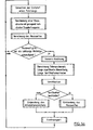
- Fig. 5a, 5b ein Flussdiagramm des Programms des Mikrorechners der Einrichtung von Fig. 4.
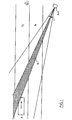
- Fig. 1 zeigt zwei Spuren S1und S2 einer Strasse, beispielsweise der einen Hälfte einer Autobahn, mit einem in Richtung des eingezeichneten Pfeiles fahrenden Fahrzeug F auf der Ueberholspur S2. Seitlich der Normalspur S1 ist ein Radargerät mit Kamera R+K aufgestellt, welches den entgegenkommenden Verkehr überwacht. Das Radargerät sendet die schraffiert eingezeichnete Messkeule M aus, die Kamera hat den Oeffnungswinkel a. Radargerät und Kamera R+K können in ein Fahrzeug eingebaut oder auf einem Stativ angeordnet sein. Der Messwinkel zur Fahrtrichtung beträgt etwa 22°.
- 1 is a schematic representation of the geometry of the installation of a device according to the invention on a street with two lanes per direction of travel,
- 2, 3 each a diagram of a specific traffic situation with two vehicles in the measuring lobe in the upper half and with the corresponding speed diagram in the lower half,
- Fig. 4 is a block diagram of the inventive device, and
- 5a, 5b show a flowchart of the program of the microcomputer of the device of FIG. 4.
- 1 shows two lanes S1 and S 2 of a road, for example one half of a freeway, with a vehicle F traveling in the direction of the arrow in the overtaking lane S 2 . A radar device with camera R + K is set up to the side of the normal gauge S 1 , which monitors oncoming traffic. The radar device sends out the hatched measuring lobe M, the camera has the opening angle a. Radar device and camera R + K can be installed in a vehicle or arranged on a tripod. The measuring angle to the direction of travel is approximately 22 °.
Sobald das Fahrzeug F so wie in der Figur dargestellt mit seiner Front in die Messkeule M einfährt, reflektiert es die Radarstrahlung und es wird im Radargerät in bekannter Weise durch Ueberlagerung eines Teils der Sendeenergie mit der vom Fahrzeug reflektierten Empfangsenergie eine elektrische Schwingung, das Dopplersignal erzeugt, dessen Frequenz, die Dopplerfrequenz der Relativgeschwindigkeit zwischen Fahrzeug und Radargerät proportional ist. Diese Vorgänge sind in der DE-PS 1 805 903, auf welche hiermit Bezug genommen wird, ausführlich beschrieben.As soon as the vehicle F enters the measuring lobe M with its front, as shown in the figure, it reflects the radar radiation and, in a known manner, an electrical oscillation, the Doppler signal, is generated in the radar device by superimposing a portion of the transmission energy on the reception energy reflected by the vehicle whose frequency, the Doppler frequency is proportional to the relative speed between the vehicle and the radar. These processes are described in detail in DE-PS 1 805 903, to which reference is hereby made.
Sobald sich die Dopplerfrequenz nach der Einfahrt des Fahrzeuges F in die Messkeule M während eines bestimmten Messabschnittes stabilisiert hat, wird ähnlich wie bei dem in der DE-PS 1 805 903 beschriebenen Verfahren, aus dem Durchschnitt der während dieses Messabschnitts stabilen Dopplerfrequenz ein Geschwindigkeitsmesswert bestimmt und gespeichert. Sobald dieser einen gespeicherten Geschwindigkeitsgrenzwert für die am Messort zulässige Höchstgeschwindigkeit überschreitet, wird die Kamera ausgelöst und das Fahrzeug von vorne photographiert; der Film wird jedoch nicht weitertransportiert. Anschliessend wird die Dopplerfrequenz auf ihr zeitliches Verhalten im Vergleich zum zuvor gespeicherten Geschwindigkeitsmesswert hin überprüft. Dazu wird zunächst ein auf diesen gespeicherten Geschwindigkeitsmesswert bezogener Toleranzbereich von beispielsweise ± 3% bestimmt und es werden aus dem Geschwindigkeitsmesswert Zeitwerte errechnet, die gewissen Streckenlängen entsprechen, welche das Fahrzeug F zurücklegt. Es wird ein Streckenabschnitt, die sogenannte Verifikationsstrecke von beispielsweise 3 m Länge definiert, innerhalb welchem die Dopplerfrequenz keine signifikanten Abweichungen vom gespeicherten Geschwindigkeitsmesswert aufweisen darf. Als signifikante Abweichung wird ein ununterbrochenes Verlassen des Toleranzbereichs während einer eine gewisse Grenzlänge von beispielsweise 1 m überschreitenden Strecke definiert. Darunterliegende Ueber- oder Unterschreitungen des Toleranzbereichs, wie sie bei jeder Messung auch ohne die Präsenz weiterer Fahrzeuge in der Messkeule auftreten können, werden hingegen toleriert und führen daher nicht zu einer Annullation der Messung.As soon as the Doppler frequency has stabilized after the vehicle F has entered the measuring lobe M during a specific measuring section, a speed measurement value is determined from the average of the Doppler frequency stable during this measuring section and similar to the method described in DE-PS 1 805 903 saved. As soon as this exceeds a stored speed limit for the maximum speed permitted at the measurement location, the camera is triggered and the vehicle is photographed from the front; however, the film will not be transported further. The Doppler frequency is then checked for its temporal behavior in comparison to the previously stored speed measurement value. For this purpose, a tolerance range of, for example, ± 3%, based on this stored speed measurement value, is first determined and time values are calculated from the speed measurement value, which correspond to certain route lengths which the vehicle F travels. A section of the route, the so-called verification section of, for example, a length of 3 m is defined, within which the Doppler frequency must not show any significant deviations from the stored speed measurement value. A significant deviation is defined as an uninterrupted leaving of the tolerance range during a distance exceeding a certain limit length of, for example, 1 m. On the other hand, exceeding or falling below the tolerance range, as can occur with every measurement even without the presence of other vehicles in the measuring lobe, are tolerated and therefore do not lead to a cancellation of the measurement.
Wenn während der Verifikationsstrecke keine derartigen signifikanten Abweichungen der Dopplerfrequenz vom gespeicherten Geschwindigkeitsmesswert auftreten, dann wird daraus abgeleitet, dass sich keine weiteren Fahrzeuge in unmittelbarer Nähe des angemessenen Fahrzeugs F aufhalten, so dass die Zuordnung des Geschwindigkeitsmesswertes zum zuvor photographierten Fahrzeug F gesichert ist. Erst jetzt wird der Geschwindigkeitsmesswert in die schon gemachte Aufnahme eingeblendet. Anschliessend wird der Film weitertransportiert und die Kamera ist für eine neue Aufnahme bereit.If no such significant deviations of the Doppler frequency from the stored speed measurement value occur during the verification route, it is deduced from this that there are no further vehicles in the immediate vicinity of the appropriate vehicle F, so that the assignment of the speed measurement value to the previously photographed vehicle F is ensured. Only now is the speed measurement displayed in the picture already taken. The film is then transported on and the camera is ready for a new shot.
Wenn während der Verifikationsstrecke mindestens eine signifikante Abweichung der Dopplerfrequenz vom gespeicherten Geschwindigkeitsmesswert auftritt, dann besteht die Wahrscheinlichkeit der gleichzeitigen Anwesenheit mehrerer Fahrzeuge in der Messkeule, wodurch eine sichere Zuordnung des Geschwindigkeitsmesswertes zu einem bestimmten dieser Fahrzeuge unmöglich ist. Daher wird nach Ablauf der Verifikationsstrecke die Messung annulliert, indem in die schon gemachte Aufnahme anstatt des Geschwindigkeitsmesswertes eine spezielle Annullationsanzeige, beispielsweise zwei Striche --, eingeblendet wird. Anschliessend wird der Film weitertransportiert und die Kamera ist für eine neue Aufnahme bereit.If at least one significant deviation of the Doppler frequency from the stored speed measurement value occurs during the verification route, then there is a probability of the simultaneous presence of several vehicles in the measuring lobe, thereby reliably assigning the Speed reading to a particular one of these vehicles is impossible. Therefore, after the verification route has expired, the measurement is canceled by inserting a special cancellation display, for example two lines, into the picture already taken instead of the speed measurement value. The film is then transported on and the camera is ready for a new shot.
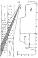
Diese eben beschriebenen Vorgänge sollen nun anhand von zwei in den Figuren 2 und 3 dargestellten Beispielen erläutert werden. Dabei sind die Fahrzeuge in der Messkeule M jeweils nur durch ihre Front symbolisiert, deren jeweilige Position für verschiedene Zeitpunkte tl bis t18 eingezeichnet ist. Da die Fahrzeuge mit unterschiedlicher Geschwindigkeit fahren, sind in den beiden Spuren S1 und S2 die den gefahrenen Strecken zwischen den einzelnen Zeitpunkten entsprechenden Abstände.verschieden gross, oder mit anderen Worten, dasjenige Fahrzeug, bei dem die Abstände zwischen den einzelnen Zeitpunkten grösser sind, fährt schneller. In den Fig. 2 und 3 ist jeweils in der oberen Hälfte das Diagramm der jeweiligen Verkehrssituation und in der unteren Hälfte das entsprechende Geschwindigkeitsdiagramm dargestellt.These processes just described will now be explained with reference to two examples shown in FIGS. 2 and 3. The vehicles in the measuring lobe M are only symbolized by their front, the respective position of which is shown for different times t 1 to t 18 . Since the vehicles are traveling at different speeds, the distances corresponding to the distances traveled between the individual times in the two lanes S 1 and S 2 are different, or in other words, the vehicle in which the distances between the individual times are greater , drives faster. 2 and 3 each show the diagram of the respective traffic situation in the upper half and the corresponding speed diagram in the lower half.
Fig. 2 zeigt in der Spur S2 ein langsameres Fahrzeug F2, welches von einem schnelleren Fahrzeug F1 auf der Spur S1 rechts überholt wird. Das Fahrzeug F2 fährt zum Zeitpunkt t1 zuerst in die Messkeule M ein und löst die Messung aus, das Fahrzeug F1 gelangt erst zum Zeitpunkt t3 in die Messkeule. Während des Zeitintervalls t2 bis t3, das der Länge der Messstrecke A entsprechen soll, bleibt die Dopplerfrequenz stabil, sodass zum Zeitpunkt t3 folgende Vorgänge ablaufen:
- - Bestimmung des Geschwindigkeitsmesswerts und dessen Speicherung (es sei angenommen, dass die zulässige Höchstgeschwindigkeit unter 60 km/h liege),
- - Festlegung des Toleranzbereichs C,
- - Festlegung der Länge einer signifikanten Abweichung,
- - Festlegung der Länge der Verifikationsstrecke B,
- - Auslösung der Kamera.
- - determination of the speed measurement value and its storage (it is assumed that the permissible maximum speed is below 60 km / h),
- - definition of the tolerance range C,
- - determining the length of a significant deviation,
- - determining the length of the verification route B,
- - Triggering the camera.
Ebenfalls zum Zeitpunkt t3 fährt das Fahrzeug F1 - mit höherer Geschwindigkeit als das Fahrzeug F2 - in die Messkeule M ein. Daher verlässt die Dopplerfrequenz schon bald darauf den Toleranzbereich C, und zwar nicht nur vorübergehend, sondern über die gesamte restliche Länge der Verifikationsstrecke B. Es wird deshalb eine signifikante Abweichung der Dopplerfrequenz vom gespeicherten Geschwindigkeitsmesswert innerhalb der Verifikationsstrecke B festgestellt. Daher wird nach Ende der Verifikationsstrecke zum Zeitpunkt t6 in die bereits gemachte Aufnahme ein Annullationszeichen -eingeblendet und anschliessend wird der Film weitertransportiert. Auf der Aufnahme wird man die beiden Fahrzeuge F1 und F2 bemerken können, deren gegenseitiger Abstand so gering ist, dass eine Messwertzuordnung nicht möglich ist.Also at time t 3 , the vehicle F 1 enters the measuring lobe M at a higher speed than the vehicle F 2 . Therefore, the Doppler frequency soon leaves the tolerance range C, and not just temporarily, but over the entire remaining length of the verification path B. A significant deviation of the Doppler frequency from the stored speed measurement value is therefore found within the verification path B. Therefore, after the end of the verification route at time t 6, a cancellation sign is superimposed on the picture already taken and the film is then transported on. On the picture you will be able to see the two vehicles F 1 and F 2 , whose mutual distance is so small that it is not possible to assign measured values.
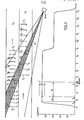
Bei dem in Fig. 3 dargestellten Beispiele fahren zwei Fahrzeuge F1 und F2 zum gleichen Zeitpunkt t1 in die Messkeule M ein und zwar das Fahrzeug F1 mit einer Geschwindigkeit von etwa 90 km/h und das Fahrzeug F2 mit einer solchen von etwa 60 km/h. Das Fahrzeug F1 deckt das Fahrzeug F2 vollständig ab, so dass die Dopplerfrequenz sofort zum Wert für das Fahrzeug F1 ansteigt und auf diesem Wert verbleibt, bis das Fahrzeug F1 mit seinem Heck kurz nach dem Zeitpunkt t8 aus der Messkeule M ausfährt. Anschliessend nimmt zwar die Dopplerfrequenz einen Wert entsprechend der Geschwindigkeit des langsameren Fahrzeugs F2 an, was jedoch die erfolgreiche Messung und Registrierung des Fahrzeugs F1 auf der Spur S1 nicht verhindert.In the example shown in FIG. 3, two vehicles F 1 and F 2 drive into the measuring lobe M at the same time t 1, namely the vehicle F 1 at a speed of approximately 90 km / h and the vehicle F 2 at such a speed about 60 km / h. The vehicle F 1 completely covers the vehicle F 2 , so that the Doppler frequency increases immediately to the value for the vehicle F 1 and remains at this value until the rear of the vehicle F 1 leaves the measuring lobe M shortly after the time t 8 . Subsequently, the Doppler frequency adopts a value corresponding to the speed of the slower vehicle F 2 , but this does not prevent the successful measurement and registration of the vehicle F 1 on the track S 1 .
Die Dopplerfrequenz erreicht zum Zeitpunkt t einen Wert, von dem sie bis zum Zeitpunkt tb, an dem die Messstrecke A beendet ist, nicht massgeblich abweicht, so dass während der Messstrecke A aufgrund des Durchschnittwertes ein zuverlässiger Geschwindigkeitsmesswert gebildet werden kann. Mit diesem Messwert werden nun ein Toleranzbereich C, die Länge einer signifikanten Abweichung und die Länge der Verifikationsstrecke B bestimmt und es wird ausserdem zum Zeitpunkt tb nach der Bestimmung des Geschwindigkeitsmesswertes die Kamera ausgelöst der Film jedoch noch nicht weitertransportiert. Da der Geschwindigkeitsmesswert grösser ist als beim Beispiel von Fig. 2, ist auch der Toleranzbereich C grösser und die Zeit, in der die Mess- und die Verifikationsstrecke A bzw. B durchfahren werden, ist entsprechend kürzer.The Doppler frequency reaches a value at the time t from which it does not deviate significantly until the time t b at which the measurement section A is ended, so that a reliable speed measurement value can be formed during the measurement section A on the basis of the average value. With this measured value, a tolerance range C, the length of a significant deviation and the length of the verification distance B are now determined and the camera is also triggered at time t b after the determination of the speed measured value, but the film has not yet been transported. Since the speed measurement value is greater than in the example of FIG. 2, the tolerance range C is also greater and the time in which the measurement and verification sections A and B are traveled is correspondingly shorter.
Da das langsamere Fahrzeug F2 auch über die Verifikationsstrecke B vollkommen abgedeckt bleibt, treten während der entsprechenden Zeitspanne keine signifikanten Abweichungen der Dopplerfrequenz vom gespeicherten Geschwindigkeitswert auf. Daher wird am Ende der Verifikationsstrecke, zum Zeitpunkt tc, der Geschwindigkeitsmesswert 90 km/h in die schon gemachte Aufnahme eingeblendet und anschliessend der Film weitertransportiert.Since the slower vehicle F 2 also remains completely covered over the verification route B, there are no significant deviations of the Doppler frequency from the stored speed value during the corresponding time period. Therefore, at the end of the verification route, at time t c , the
Die Aufnahme kann auch einwandfrei ausgewertet werden, obwohl darauf zwei Fahrzeuge F1 und F2 zu erkennen sind. Denn die Tatsache, dass ein Geschwindigkeitsmesswert und keine Annullationsanzeige eingeblendet ist, beweist, dass das hintere Fahrzeug F2 bei der Messung nicht massgeblich in Erscheinung getreten ist. Denn wenn das Fahrzeug F2 schneller gefahren wäre, dann hätte es während der Verifikationsstrecke die Dopplerfrequenz beeinflusst und es wären signifikante Abweichungen aufgetreten, so dass eine Annullationsanzeige eingeblendet worden wäre.The recording can also be evaluated correctly, although two vehicles F 1 and F 2 can be seen on it. The fact that a speed measurement value and no cancellation display is shown proves that the rear vehicle F 2 did not appear significantly during the measurement. Because if the vehicle F 2 had driven faster, it would have influenced the Doppler frequency during the verification route and significant deviations would have occurred, so that a cancellation display would have been shown.
Die beiden in den Fig. 2 und 3 dargestellten Verkehrssituationen sind lediglich Beispiele zur Erläuterung der Funktions- und Wirkungsweise des erfindungsgemässen Verfahrens. Es sind selbstverständlich viele weitere Verkehrssituationen denkbar, in denen das erfindungsgemässe Verfahren ebenfalls besonders nutzbringend angewendet werden kann. Die in der Beschreibung verwendeten Begriffe Kamera und Film sind nicht so zu verstehen, dass das beschriebene Verfahren auf heute übliche photographische Filme und Kameras eingeschränkt wäre, sie bezeichnen vielmehr jede denkbare Aufzeichnungs- und Registriereinrichtung und jedes dafür geeignete Medium. So könnte man beispielsweise auch elektronische Videokameras und Magnetbänder oder Disketten verwenden.The two traffic situations shown in FIGS. 2 and 3 are merely examples to explain the functioning and mode of operation of the method according to the invention. Of course, many other traffic situations are conceivable in which the method according to the invention can also be used in a particularly useful manner. The terms camera and film used in the description are not to be understood in such a way that the described method would be restricted to photographic films and cameras that are common today; rather, they refer to every conceivable recording and registration device and every suitable medium. For example, you could also use electronic video cameras and magnetic tapes or diskettes.
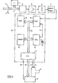
In Fig. 4 ist ein Blockschaltbild einer Vorrichtung zur Durchführung des erfindungsgemässen Verfahrens dargestellt. Ein Mikrowellenoszillator 1 erzeugt ein Mikrowellensignal, welches über einen Hohlleiter 2 einer Antenne 3 zugeführt und von dieser gebündelt abgestrahlt wird. Sobald ein Fahrzeug durch den Strahlungsbereich der Antenne 3 fährt, werden von diesen Strahlungsanteile zur Antenne 3 reflektiert. Diese reflektierten Strahlungsanteile sind gegenüber den ursprünglich von der Antenne 3 abgestrahlten um einen Betrag verschoben, welcher proportional zur Geschwindigkeit des Fahrzeuges ist. Diese Erscheinung bezeichnet man als Dopplereffekt und die Frequenzverschiebung als Dopplerfrequenz.4 shows a block diagram of a device for carrying out the method according to the invention. A microwave oscillator 1 generates a microwave signal which is fed to an
Die von der Antenne 3 empfangenen reflektierten Strahlungsanteile werden über den Hohlleiter 2 einem Mischer 4 zugeführt, zu welchem ausserdem auch ein kleiner Teil des vom Mikrowellenoszillator erzeugten ursprünglichen Mikrowellensignals gelangt. Die beiden erwähnten Signale werden im Mischer 4 gemischt und das sich daraus ergebende Mischprodukt, eine niederfrequente Wechselspannung mit der Dopplerfrequenz, wird an den Eingang eines Verstärkers 5 gelegt. Dessen Ausgangssignal wird dem Eingang eines Filters 6 zugeführt, welches nur für den für die weitere Auswertung interessierenden Teil des Spektrums, das ist die zum Geschwindigkeitsmessbereich des Radargeräts gehörende Dopplerspektralkomponente, durchlässig ist. Dadurch werden die Anteile der Rauschspannung ausserhalb des Durchlassbereichs des Filters 6 eliminiert, so dass das Signal-Rausch-Verhältnis verbessert wird. Das am Ausgang des Filters 6 erscheinende Signal wird anschliessend von einem Schmitt-Trigger 7 digitalisiert.The reflected radiation components received by the
Das am Ausgang des Schmitt-Triggers 7 abnehmbare Digitalsignal enthält sämtliche nutzbare Informationen über die Geschwindigkeit der sich im Radarstrahl bewegenden Objekte. Es wird an den Eingang eines zu einem Mikrorechner 10 gehörenden Timers 11 (z.B. INTEL 8253) geführt, in welchem die Zeitintervalle zwischen den logischen Wechseln im digitalisierten Dopplersignal sequentiell gemessen und dem Mikrorechner 11 zur Auswertung angeboten werden. Der Mikrorechner enthält ausser dem Timer 11 noch eine Zentraleinheit (CPU) 12 (z.B. INTEL 8085) mit einem Quarz 13, welcher an den Timer 11 über eine Leitung 14 ein Taktsignal abgibt, einen löschbaren, programmierbaren Festwertspeicher (EPROM) 15 (z.B. INTEL 2764), einen Datenspeicher mit beliebigem Zugriff (RAM) 16 (z.B. INTEL 8185) und eine Ein/Ausgabestufe (I/0) 17 (z.B. INTEL 8255), welche alle durch eine Sammelschiene 18 für die Uebergabe von Daten, Adressen und Steuersignalen verbunden sind.The digital signal which can be taken off at the output of the
Ueber die Ein/Ausgabestufe 17 wird eine Registrierkamera K mit einer Daten- einblende-Einrichtung D angesteuert. Die Kamera K ist über Leitungen 8 und 9 für das Kamera-Auslöse- bzw. das Filmtransportsignal und die Dateneinblende-Einrichtung D ist mittels einer Sammelschiene 19 für die einzublendenden Daten und einer Leitung 20 für das Daten-Einblende-Signal mit der Ein/Ausgabestufe 17 verbunden. Der Datenspeicher 16 dient zur vorübergehenden Speicherung von variablen Daten und von Zwischenresultaten und der programmierbare Festwertspeicher 15 enthält in binärem Code das Programm des Mikrorechners 10.A registration camera K with a data insertion device D is controlled via the input /
Dieses Programm wird nun anhand des in den Figuren 5a und 5b dargestellten Flussdiagrammes beschrieben:
- Ein Messvorgang wird gemäss Fig. 5a mit der Detektion der Einfahrt eines Fahrzeuges F in die Messkeule M (Fig. 1) eingeleitet. Diese Einfahrt kann festgestellt werden durch das Eintreffen einer Reihe von Pegelwechseln im Digitalsignal (
Eingang Timer 11, Fig. 4) mit einer minimalen Frequenz nach einer Periode ohne Pegelwechsel. Nach der Detektion der Einfahrt wird die Dopplerfrequenz auf Konstanz überprüft und nach Ablauf einer gewissen Strecke mit ausreichend konstanter Dopplerfrequenz wird aufgrund des Durchschnittswerts der Dopplerfrequenz auf dieser Strecke der Geschwindigkeitsmesswerte berechnet.
- A measuring process is initiated according to FIG. 5a with the detection of the entry of a vehicle F into the measuring lobe M (FIG. 1). This entry can be determined by the arrival of a series of level changes in the digital signal (
input timer 11, FIG. 4) with a minimum frequency after a period without level change. After detection of the entrance, the Doppler frequency is checked for constancy and, after a certain distance with a sufficiently constant Doppler frequency, the speed measured values are calculated on the basis of the average value of the Doppler frequency.
Liegt dieser unterhalb der zulässigen Höchstgeschwindigkeit, dann wird keine Aufnahme ausgelöst und bis zur Detektion der Einfahrt des nächsten Fahrzeugs gewartet. Uebersteigt der Messwert die zulässige Höchstgeschwindigkeit, dann wird sofort die Kamera ausgelöst und es werden anschliessend die für die Durchführung der Verifikation benötigten Werte berechnet, und zwar der Toleranzbereich, die Länge einer signifikanten Abweichung und die Länge der Verifikationsstrecke.If this is below the permissible maximum speed, then no recording is triggered and the system waits until the next vehicle's entrance is detected. If the measured value exceeds the permissible maximum speed, the camera is triggered immediately and the values required for carrying out the verification are then calculated, namely the tolerance range, the length of a significant deviation and the length of the verification route.
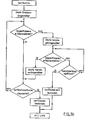
Die Verifikation ist in Fig. 5b gesondert dargestellt: Zu Beginn der Verifikation wird ein im Timer 11 (Fig. 4) enthaltener Zähler welcher die abgelaufene Länge der Verifikationsstrecke messen soll, gestartet. Anschliessend wird überprüft, ob die zuletzt gemessene Dopplerperiode innerhalb des festgelegten Toleranzbereichs liegt. Ist dies der Fall, dann wird hierauf der Streckenlängenzähler abgefragt, ob die Verifikationsstrecke schon abgelaufen ist. Ist dies nicht der Fall, dann wird die nächste Dopplerperiode daraufhin überprüft, ob sie innerhalb des Toleranzbereichs liegt. Liegt auch diese innerhalb des Toleranzbereichs, so wird wiederum der Streckenlängenzähler abgefragt, und so weiter. Bleibt die Dopplerfrequenz über die gesamte Verifikationsstrecke im Toleranzbereich, dann wird am Ende dieser Strecke die Verifikation erfolgreich abgeschlossen und es findet ein Rücksprung ins Hauptprogramm (Fig. 5a) statt.The verification is shown separately in FIG. 5b: At the beginning of the verification, a counter contained in the timer 11 (FIG. 4) which is to measure the elapsed length of the verification route is started. It is then checked whether the last measured Doppler period is within the fixed tolerance range. If this is the case, the route length counter is then queried as to whether the verification route has already expired. If this is not the case, the next Doppler period is checked to determine whether it is within the tolerance range. If this is also within the tolerance range, the route length counter is queried again, and so on. If the Doppler frequency remains within the tolerance range over the entire verification path, then the verification is successfully completed at the end of this path and a return is made to the main program (FIG. 5a).
Sobald jedoch eine Dopplerperiode mit einer Länge ausserhalb des Toleranzbereichs gemessen wird, wird das Programm zu einem Seitenast verzweigt. Hier wird zuerst ein im Timer 11 (Fig. 4) enthaltener Ausreisserlängenzähler gestartet, der die Länge des soeben detektierten "Ausreissers", d.h. die Zeitspanne, während welcher die Dopplerfrequenz ausserhalb des Toleranzbereichs liegt, messen soll. Anschliessend wird die Länge der nächsten Dopplerperiode gemessen. Liegt auch diese ausserhalb des Toleranzbereichs, dann wird der Ausreisserlängenzähler abgefragt. Hat der aktuelle Ausreisser noch nicht die Länge einer signifikanten Abweichung erreicht, dann wird die Länge der nächsten Dopplerperiode gemessen.However, as soon as a Doppler period with a length outside the tolerance range is measured, the program branches to a side branch. Here, an outlier length counter contained in the timer 11 (FIG. 4) is first started, which counts the length of the "outlier" just detected, i.e. measure the time period during which the Doppler frequency is outside the tolerance range. The length of the next Doppler period is then measured. If this is also outside the tolerance range, the outlier length counter is queried. If the current outlier has not yet reached the length of a significant deviation, the length of the next Doppler period is measured.
Dieser Prozess wiederholt sich so lange, bis entweder eine Dopplerperiode mit einer Länge innerhalb des Toleranzbereichs gemessen wird, oder der Ausreisserlängenzähler den Stand für eine signifikante Abweichung erreicht. Im ersten Fall (Dopplerfrequenz wieder im Toleranzbereich) wird der Ausreisserlängenzähler auf Null gesetzt und wieder die erste Programmschleife angesprungen, im zweiten Fall (Ausreisserlänge wird signifikant) wird die Veriifikation erfolglos abgeschlossen und ins Hauptprogramm (Fig. 5a) zurückgesprungen.This process is repeated until either a Doppler period with a length within the tolerance range is measured or the outlier length counter reaches the level for a significant deviation. In the first case (Doppler frequency again within the tolerance range) the outlier length counter is set to zero and the first program loop is started again, in the second case (outlier length becomes significant) the verification is completed unsuccessfully and the program returns to the main program (Fig. 5a).
Im Hauptprogramm (Fig. 5a) wird im Fall einer bestandenen Verifikation der Geschwindigkeitsmesswert in die Dateneinblende-Einrichtung D (Fig. 4) übertragen und das Einblendesignal ausgegeben. Im Fall einer nicht bestandenen Verifikation wird das Annullationszeichen -- zur Dateneinblende-Einrichtung übertragen und ebenfalls das Einblendesignal ausgegeben. Schliesslich wird an die Kamera K (Fig. 4) das Filmtransportsignal abgegeben und anschliessend die Detektion der Einfahrt des nächsten Fahrzeugs abgewartet.In the main program (FIG. 5a), in the event of verification being passed, the speed measurement value is transmitted to the data insertion device D (FIG. 4) and the insertion signal is output. In the event of a failed verification, the cancellation symbol - is transmitted to the data insertion device and the insertion signal is likewise output. Finally, the film transport signal is emitted to the camera K (FIG. 4) and the detection of the entrance of the next vehicle is then awaited.
Claims (9)
Priority Applications (1)
| Application Number | Priority Date | Filing Date | Title |
|---|---|---|---|
| AT85114741T ATE57033T1 (en) | 1984-11-30 | 1985-11-19 | METHOD AND DEVICE FOR PHOTOGRAPHIC REGISTRATION OF VEHICLES. |
Applications Claiming Priority (2)
| Application Number | Priority Date | Filing Date | Title |
|---|---|---|---|
| CH5721/84A CH662660A5 (en) | 1984-11-30 | 1984-11-30 | METHOD AND DEVICE FOR IMAGING, IN PARTICULAR PHOTOGRAPHIC, REGISTRATION OF ACCOMPANYING VEHICLES. |
| CH5721/84 | 1984-11-30 |
Publications (3)
| Publication Number | Publication Date |
|---|---|
| EP0188694A2 true EP0188694A2 (en) | 1986-07-30 |
| EP0188694A3 EP0188694A3 (en) | 1988-03-30 |
| EP0188694B1 EP0188694B1 (en) | 1990-09-26 |
Family
ID=4298254
Family Applications (1)
| Application Number | Title | Priority Date | Filing Date |
|---|---|---|---|
| EP85114741A Expired - Lifetime EP0188694B1 (en) | 1984-11-30 | 1985-11-19 | Method and device for the photographic registration of vehicles |
Country Status (7)
| Country | Link |
|---|---|
| US (1) | US4717915A (en) |
| EP (1) | EP0188694B1 (en) |
| AT (1) | ATE57033T1 (en) |
| AU (1) | AU585275B2 (en) |
| CH (1) | CH662660A5 (en) |
| DE (1) | DE3579907D1 (en) |
| ES (1) | ES8705126A1 (en) |
Cited By (9)
| Publication number | Priority date | Publication date | Assignee | Title |
|---|---|---|---|---|
| EP0286910A3 (en) * | 1987-04-11 | 1989-07-12 | Robot Foto & Electronic Gmbh & Co Kg | Traffic surveillance device |
| EP0350751A3 (en) * | 1988-07-14 | 1990-07-18 | Multanova Ag | Method and apparatus for monitoring the speed of vehicles using a doppler radar speed measuring device, and application of the method |
| DE4326398C1 (en) * | 1993-08-06 | 1994-07-21 | Leica Sensortechnik Gmbh | Traffic monitoring method and device |
| FR2718874A1 (en) * | 1994-04-15 | 1995-10-20 | Thomson Csf | Traffic monitoring method for automatic vehicle incident detection. |
| US5912822A (en) * | 1994-06-01 | 1999-06-15 | American Traffic Systems, Inc. | Frequency domain processing of Doppler signals in a traffic monitoring system |
| US5935190A (en) * | 1994-06-01 | 1999-08-10 | American Traffic Systems, Inc. | Traffic monitoring system |
| WO2008006817A1 (en) * | 2006-07-13 | 2008-01-17 | Siemens Aktiengesellschaft | Method for the detection of at least one moving object |
| EP2708902A1 (en) * | 2012-09-12 | 2014-03-19 | Münz, Christoph | Symmetrical and asymmetrical speed detection and decentralized data processing |
| EP2799903A3 (en) * | 2013-04-30 | 2015-03-25 | Jenoptik Robot GmbH | Method for detecting speeding offences with restrictive data storage |
Families Citing this family (18)
| Publication number | Priority date | Publication date | Assignee | Title |
|---|---|---|---|---|
| IT1221607B (en) * | 1987-08-25 | 1990-07-12 | Fiorello Sodi | SYSTEM FOR THE DETECTION AND REGISTRATION OF INFRINGEMENTS TO THE RULES OF THE ROAD DISCIPLINE, WITH THE USE OF LASER |
| DE4042494C2 (en) * | 1990-03-08 | 1998-10-29 | Conner Joe Scott O | Device in a vehicle for displaying relative speeds to other vehicles |
| DE4013037A1 (en) * | 1990-04-24 | 1991-10-31 | Standard Elektrik Lorenz Ag | Method of mobile traffic surveillance - using moving detector vehicle with radar which detects speed of vehicles being observed |
| US5408330A (en) * | 1991-03-25 | 1995-04-18 | Crimtec Corporation | Video incident capture system |
| US6204802B1 (en) | 1991-11-15 | 2001-03-20 | O'conner Joe Scott | Apparatus for detecting relative velocity |
| DE4400624A1 (en) * | 1994-01-12 | 1995-07-13 | Conner Joe Scott O | Vehicle speed measurement installation for traffic monitoring |
| US6111523A (en) * | 1995-11-20 | 2000-08-29 | American Traffic Systems, Inc. | Method and apparatus for photographing traffic in an intersection |
| US5938717A (en) * | 1996-03-04 | 1999-08-17 | Laser Technology, Inc. | Speed detection and image capture system for moving vehicles |
| US5948038A (en) * | 1996-07-31 | 1999-09-07 | American Traffic Systems, Inc. | Traffic violation processing system |
| US6696978B2 (en) | 2001-06-12 | 2004-02-24 | Koninklijke Philips Electronics N.V. | Combined laser/radar-video speed violation detector for law enforcement |
| US7250853B2 (en) * | 2004-12-10 | 2007-07-31 | Honeywell International Inc. | Surveillance system |
| DE102007022373A1 (en) * | 2007-05-07 | 2008-11-13 | Robot Visual Systems Gmbh | Method for conclusively detecting the speed of a vehicle |
| TW201133412A (en) * | 2010-03-19 | 2011-10-01 | Cct Co Ltd | Method of using radar vehicle detector to determine vehicle type, speed, and radar detection zone width |
| US10451727B2 (en) * | 2011-05-13 | 2019-10-22 | Amirahmad Sepehri | Method and system for detecting moving vehicle speed through athird generation photo radar |
| SI2804013T1 (en) * | 2013-05-13 | 2015-08-31 | Kapsch Trafficcom Ag | Device for measuring the position of a vehicle or a surface thereof |
| PL2804014T3 (en) * | 2013-05-13 | 2015-10-30 | Kapsch Trafficcom Ag | Device and method for determining a characteristic of a vehicle |
| CN107219879B (en) * | 2017-07-21 | 2022-11-25 | 电子科技大学成都学院 | Environmental conditioning system and warmhouse booth |
| CN112598913B (en) * | 2020-12-17 | 2022-10-04 | 多伦信息技术有限公司 | Bus priority control method and device based on waiting factors and electronic equipment |
Family Cites Families (11)
| Publication number | Priority date | Publication date | Assignee | Title |
|---|---|---|---|---|
| US3122740A (en) * | 1957-01-10 | 1964-02-25 | Admiral Corp | Velocity determining device |
| US3195126A (en) * | 1957-05-13 | 1965-07-13 | Lab For Electronics Inc | Traffic supervisory system |
| US3148015A (en) * | 1961-07-19 | 1964-09-08 | Weaver Scott | Apparatus for photographing a traffic violator |
| US3206748A (en) * | 1962-12-27 | 1965-09-14 | Miller Robert William | Vehicle speed recording apparatus |
| US3438031A (en) * | 1967-11-13 | 1969-04-08 | Duncan Parking Meter Corp | Doppler radar having digital speed indicator |
| CH470674A (en) * | 1968-02-15 | 1969-03-31 | Zellweger Uster Ag | Method and device for triggering a camera in a Doppler radar speed measuring device |
| US3626413A (en) * | 1970-02-02 | 1971-12-07 | Howard C Zachmann | Traffic surveillance and control system |
| FR2250170A1 (en) * | 1973-11-07 | 1975-05-30 | Automatisme Cie Gle | Moving vehicle photographing device - has radar controlling a camera through a threshold circuit |
| DE2802448C2 (en) * | 1978-01-20 | 1982-03-18 | Dieter 8000 München Schwenk | Method and device for producing photographs of vehicle occupants |
| FR2466060A1 (en) * | 1979-06-28 | 1981-03-27 | Sfim | MOTOR VEHICLE SPEED CONTROL SYSTEM |
| CH654670A5 (en) * | 1981-06-22 | 1986-02-28 | Zellweger Uster Ag | Method and device for evaluating signals of a doppler radar speed measuring device. |
-
1984
- 1984-11-30 CH CH5721/84A patent/CH662660A5/en not_active IP Right Cessation
-
1985
- 1985-11-07 AU AU49434/85A patent/AU585275B2/en not_active Ceased
- 1985-11-19 DE DE8585114741T patent/DE3579907D1/en not_active Expired - Lifetime
- 1985-11-19 AT AT85114741T patent/ATE57033T1/en not_active IP Right Cessation
- 1985-11-19 EP EP85114741A patent/EP0188694B1/en not_active Expired - Lifetime
- 1985-11-22 US US06/800,790 patent/US4717915A/en not_active Expired - Lifetime
- 1985-11-29 ES ES549442A patent/ES8705126A1/en not_active Expired
Cited By (12)
| Publication number | Priority date | Publication date | Assignee | Title |
|---|---|---|---|---|
| EP0286910A3 (en) * | 1987-04-11 | 1989-07-12 | Robot Foto & Electronic Gmbh & Co Kg | Traffic surveillance device |
| EP0350751A3 (en) * | 1988-07-14 | 1990-07-18 | Multanova Ag | Method and apparatus for monitoring the speed of vehicles using a doppler radar speed measuring device, and application of the method |
| DE4326398C1 (en) * | 1993-08-06 | 1994-07-21 | Leica Sensortechnik Gmbh | Traffic monitoring method and device |
| US5767794A (en) * | 1993-08-06 | 1998-06-16 | Leica Sensortechnik Gmbh | traffic surveillance process and device |
| FR2718874A1 (en) * | 1994-04-15 | 1995-10-20 | Thomson Csf | Traffic monitoring method for automatic vehicle incident detection. |
| WO1995028653A1 (en) * | 1994-04-15 | 1995-10-26 | Thomson-Csf | Traffic monitoring method for the automatic detection of vehicle-related incidents |
| US5912822A (en) * | 1994-06-01 | 1999-06-15 | American Traffic Systems, Inc. | Frequency domain processing of Doppler signals in a traffic monitoring system |
| US5935190A (en) * | 1994-06-01 | 1999-08-10 | American Traffic Systems, Inc. | Traffic monitoring system |
| WO2008006817A1 (en) * | 2006-07-13 | 2008-01-17 | Siemens Aktiengesellschaft | Method for the detection of at least one moving object |
| US8035546B2 (en) | 2006-07-13 | 2011-10-11 | Siemens Aktiengesellschaft | Method for detecting at least one moving object |
| EP2708902A1 (en) * | 2012-09-12 | 2014-03-19 | Münz, Christoph | Symmetrical and asymmetrical speed detection and decentralized data processing |
| EP2799903A3 (en) * | 2013-04-30 | 2015-03-25 | Jenoptik Robot GmbH | Method for detecting speeding offences with restrictive data storage |
Also Published As
| Publication number | Publication date |
|---|---|
| ES8705126A1 (en) | 1987-04-16 |
| DE3579907D1 (en) | 1990-10-31 |
| CH662660A5 (en) | 1987-10-15 |
| ATE57033T1 (en) | 1990-10-15 |
| AU585275B2 (en) | 1989-06-15 |
| AU4943485A (en) | 1986-06-05 |
| EP0188694A3 (en) | 1988-03-30 |
| EP0188694B1 (en) | 1990-09-26 |
| US4717915A (en) | 1988-01-05 |
| ES549442A0 (en) | 1987-04-16 |
Similar Documents
| Publication | Publication Date | Title |
|---|---|---|
| EP0188694B1 (en) | Method and device for the photographic registration of vehicles | |
| DE69734474T2 (en) | Vehicle detection system and signal processing system therefor | |
| EP0286910B1 (en) | Traffic surveillance device | |
| EP2048515B1 (en) | Method for determining and documenting traffic violations at a traffic light | |
| DE69305765T2 (en) | System for measuring the distance between vehicles | |
| DE19505244C2 (en) | Device for determining the distance between vehicles | |
| DE69419189T2 (en) | Electronic toll collection system | |
| DE19518978C2 (en) | Obstacle detection device for motor vehicles | |
| EP1446678B1 (en) | Method and device for detecting and classifying moving vehicles | |
| DE19735414A1 (en) | Distance measurement device between road vehicles | |
| DD249561A5 (en) | DEVICE FOR PHOTOGRAPHIC MONITORING OF CROSSROADS | |
| WO2020187581A1 (en) | Method and device for detecting a traffic law violation due to the allowable distance between a following vehicle and a guide vehicle being undershot | |
| DE2408333A1 (en) | DEVICE FOR DISTANCE MEASUREMENT | |
| DE102014005693A1 (en) | SPEED MONITORING PROCESS FOR A VEHICLE USING WIRELESS COMMUNICATION | |
| EP0413948A1 (en) | System for optical data transmission, preferably for the automatic payment of road taxes | |
| EP0805953B1 (en) | Vehicle-locating method | |
| EP2341367A2 (en) | Method and assembly for detecting traffic violations in an area with traffic lights | |
| DE2130939A1 (en) | Traffic monitoring system | |
| EP2656105A1 (en) | Method for generating an image document in which a vehicle measured by a radar device can be identified and image document generated with this method | |
| WO1995004982A1 (en) | Traffic surveillance process and device | |
| EP0350751B1 (en) | Method and apparatus for monitoring the speed of vehicles using a Doppler radar speed measuring device, and application of the method | |
| DE2207487B2 (en) | Device for recording and controlling the flow of traffic on roads | |
| DE102022201200A1 (en) | Method and system for determining traffic orientation | |
| WO2005122104A1 (en) | System for the photographic monitoring of traffic by means of a video camera | |
| EP2075775B1 (en) | Method for documenting near simultaneous traffic violations |
Legal Events
| Date | Code | Title | Description |
|---|---|---|---|
| PUAI | Public reference made under article 153(3) epc to a published international application that has entered the european phase |
Free format text: ORIGINAL CODE: 0009012 |
|
| 17P | Request for examination filed |
Effective date: 19851217 |
|
| AK | Designated contracting states |
Kind code of ref document: A2 Designated state(s): AT BE DE FR GB IT NL SE |
|
| PUAL | Search report despatched |
Free format text: ORIGINAL CODE: 0009013 |
|
| AK | Designated contracting states |
Kind code of ref document: A3 Designated state(s): AT BE DE FR GB IT NL SE |
|
| 17Q | First examination report despatched |
Effective date: 19900202 |
|
| GRAA | (expected) grant |
Free format text: ORIGINAL CODE: 0009210 |
|
| AK | Designated contracting states |
Kind code of ref document: B1 Designated state(s): AT BE DE FR GB IT NL SE |
|
| PG25 | Lapsed in a contracting state [announced via postgrant information from national office to epo] |
Ref country code: SE Effective date: 19900926 Ref country code: IT Free format text: LAPSE BECAUSE OF FAILURE TO SUBMIT A TRANSLATION OF THE DESCRIPTION OR TO PAY THE FEE WITHIN THE PRESCRIBED TIME-LIMIT;WARNING: LAPSES OF ITALIAN PATENTS WITH EFFECTIVE DATE BEFORE 2007 MAY HAVE OCCURRED AT ANY TIME BEFORE 2007. THE CORRECT EFFECTIVE DATE MAY BE DIFFERENT FROM THE ONE RECORDED. Effective date: 19900926 |
|
| REF | Corresponds to: |
Ref document number: 57033 Country of ref document: AT Date of ref document: 19901015 Kind code of ref document: T |
|
| ET | Fr: translation filed | ||
| REF | Corresponds to: |
Ref document number: 3579907 Country of ref document: DE Date of ref document: 19901031 |
|
| PGFP | Annual fee paid to national office [announced via postgrant information from national office to epo] |
Ref country code: SE Payment date: 19901114 Year of fee payment: 6 |
|
| ITTA | It: last paid annual fee | ||
| GBT | Gb: translation of ep patent filed (gb section 77(6)(a)/1977) | ||
| PLBE | No opposition filed within time limit |
Free format text: ORIGINAL CODE: 0009261 |
|
| STAA | Information on the status of an ep patent application or granted ep patent |
Free format text: STATUS: NO OPPOSITION FILED WITHIN TIME LIMIT |
|
| 26N | No opposition filed | ||
| REG | Reference to a national code |
Ref country code: FR Ref legal event code: CD |
|
| REG | Reference to a national code |
Ref country code: GB Ref legal event code: 732E |
|
| PGFP | Annual fee paid to national office [announced via postgrant information from national office to epo] |
Ref country code: GB Payment date: 20001115 Year of fee payment: 16 |
|
| PGFP | Annual fee paid to national office [announced via postgrant information from national office to epo] |
Ref country code: BE Payment date: 20001116 Year of fee payment: 16 |
|
| PGFP | Annual fee paid to national office [announced via postgrant information from national office to epo] |
Ref country code: FR Payment date: 20001127 Year of fee payment: 16 Ref country code: AT Payment date: 20001127 Year of fee payment: 16 |
|
| PGFP | Annual fee paid to national office [announced via postgrant information from national office to epo] |
Ref country code: NL Payment date: 20001130 Year of fee payment: 16 |
|
| NLS | Nl: assignments of ep-patents |
Owner name: MULTANOVA AG |
|
| NLT1 | Nl: modifications of names registered in virtue of documents presented to the patent office pursuant to art. 16 a, paragraph 1 |
Owner name: ZELLWEGER LUWA AG |
|
| PGFP | Annual fee paid to national office [announced via postgrant information from national office to epo] |
Ref country code: DE Payment date: 20010125 Year of fee payment: 16 |
|
| PG25 | Lapsed in a contracting state [announced via postgrant information from national office to epo] |
Ref country code: GB Free format text: LAPSE BECAUSE OF NON-PAYMENT OF DUE FEES Effective date: 20011119 Ref country code: AT Free format text: LAPSE BECAUSE OF NON-PAYMENT OF DUE FEES Effective date: 20011119 |
|
| PG25 | Lapsed in a contracting state [announced via postgrant information from national office to epo] |
Ref country code: BE Free format text: LAPSE BECAUSE OF NON-PAYMENT OF DUE FEES Effective date: 20011130 |
|
| REG | Reference to a national code |
Ref country code: GB Ref legal event code: IF02 |
|
| BERE | Be: lapsed |
Owner name: MULTANOVA A.G. Effective date: 20011130 |
|
| PG25 | Lapsed in a contracting state [announced via postgrant information from national office to epo] |
Ref country code: NL Free format text: LAPSE BECAUSE OF NON-PAYMENT OF DUE FEES Effective date: 20020601 |
|
| PG25 | Lapsed in a contracting state [announced via postgrant information from national office to epo] |
Ref country code: DE Free format text: LAPSE BECAUSE OF NON-PAYMENT OF DUE FEES Effective date: 20020702 |
|
| GBPC | Gb: european patent ceased through non-payment of renewal fee |
Effective date: 20011119 |
|
| PG25 | Lapsed in a contracting state [announced via postgrant information from national office to epo] |
Ref country code: FR Free format text: LAPSE BECAUSE OF NON-PAYMENT OF DUE FEES Effective date: 20020730 |
|
| NLV4 | Nl: lapsed or anulled due to non-payment of the annual fee |
Effective date: 20020601 |
|
| REG | Reference to a national code |
Ref country code: FR Ref legal event code: ST |
|
| REG | Reference to a national code |
Ref country code: FR Ref legal event code: ST |