EP0187174A1 - Mobile cleaning installation for portable containers, e.g. waste bins - Google Patents
Mobile cleaning installation for portable containers, e.g. waste bins Download PDFInfo
- Publication number
- EP0187174A1 EP0187174A1 EP84402713A EP84402713A EP0187174A1 EP 0187174 A1 EP0187174 A1 EP 0187174A1 EP 84402713 A EP84402713 A EP 84402713A EP 84402713 A EP84402713 A EP 84402713A EP 0187174 A1 EP0187174 A1 EP 0187174A1
- Authority
- EP
- European Patent Office
- Prior art keywords
- support
- brush
- installation according
- brushes
- receptacle
- Prior art date
- Legal status (The legal status is an assumption and is not a legal conclusion. Google has not performed a legal analysis and makes no representation as to the accuracy of the status listed.)
- Withdrawn
Links
Images


Classifications
-
- B—PERFORMING OPERATIONS; TRANSPORTING
- B65—CONVEYING; PACKING; STORING; HANDLING THIN OR FILAMENTARY MATERIAL
- B65F—GATHERING OR REMOVAL OF DOMESTIC OR LIKE REFUSE
- B65F7/00—Cleaning or disinfecting devices combined with refuse receptacles or refuse vehicles
- B65F7/005—Devices, mounted on refuse collecting vehicles, for cleaning or disinfecting refuse receptacles
-
- B—PERFORMING OPERATIONS; TRANSPORTING
- B08—CLEANING
- B08B—CLEANING IN GENERAL; PREVENTION OF FOULING IN GENERAL
- B08B9/00—Cleaning hollow articles by methods or apparatus specially adapted thereto
- B08B9/08—Cleaning containers, e.g. tanks
- B08B9/087—Cleaning containers, e.g. tanks by methods involving the use of tools, e.g. brushes, scrapers
Definitions
- the receptacles made available to the public in streets, gardens and other public places must not only be emptied but also cleaned and, sometimes, replaced when they are damaged.
- the receptacles are emptied during the collection of household waste, or during special operations by personnel using large bulky and slow garbage bins.
- the present invention makes it possible to rationalize all the emptying, cleaning, maintenance and repair operations of portable receptacles such as baskets for waste and avoid all of the above drawbacks.
- the subject of the invention is an installation for cleaning portable receptacles such as waste baskets placed in public containers, characterized in that it comprises on the one hand a horizontal bin in which two brushes are arranged with substantially vertical axes, at least one of which is associated with a support for a receptacle, at least one motor having to drive either said axes or said support and, on the other hand, an assembly intended to set in motion, in a closed circuit, washing water comprising a strainer placed in the tank for the aspiration of water, a pump, a filter and a supply pipe ending in the vicinity of at least one of the two brushes, the tray to be placed on the floor of a vehicle, the drive motor (s) being slaved to an erasable containment element so that the motor (s) cannot be activated only when the containment element is in the active position.
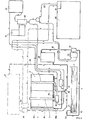
- the installation proper comprises a horizontal tank 1 above which two brushes 2 and 3 are arranged, the vertical axes 4 and 5 of which stand above the bottom 6 of the tank 1.
- Brushes 2 and 3 can be of the rigid axis type carrying relatively flexible brushing elements 7 which, at natural rest, are bent downwards and which straighten horizontally under the effect of centrifugal force when their axis is rotated.
- these brushes have the advantage of properly cleaning surfaces of shapes other than simply circular and this is often the case with waste and paper baskets that are found in public places, since they generally have a shape close to a rectangular parallelepiped or a trunk of an inverted pyramid at an angle with a very small top.
- the axis 4 of the brush 2 is surrounded by a horizontal support 10 for a receptacle B which is placed on it upside down, "styling" the brush 2.
- the axes 4 and 5 are spaced from each other by a distance which is a function of the horizontal dimensions of the receptacles B and the length of the brushing elements 7 and, this, in order to simultaneously achieve internal brushing and external brushing of the same receptacle B placed on the support 10.
- the axes 4 and 5 as well as the support 10 are rotatably mounted and are kinematically connected to one or more drive motors of which an embodiment will be described later.
- the installation includes a movable arm 11 which is associated with a fixed upright 12 provided with a helical groove 13 which serves as guide on arm 11.
- the arm 11 By actuating the arm 11, the latter is forced to automatically perform a combined movement of rotation and lowering, or lifting, according to the path of the guide groove 13.
- the end of the arm 11 carries a shoe 14 mounted idly on a vertical central axis 15.
- the arm 11 can pass, according to the arrow F1, from an erasing position represented in dotted lines to an active position represented in solid lines - and in which the shoe 14 is supported on the bottom of a receptacle B placed upside down on support 10.
- a strainer 20 In the tank 1 is a strainer 20, preferably protected by a grid 21 and placed at the end of a pipe 22 leading to a so-called "lifting" pump 23. From this leaves a pipe 24 which leads to a filter 25.
- a supply pipe 26 connects the filter 25 to the lower inlet of the hollow axis 4, pierced with at least one hole as will be described in more detail far.
- the tank 27 being at atmospheric pressure, a pump 28 is provided which sends under pressure l from the tank to brushes 2 and 3.
- the tank 1 is located opposite an access C of the vehicle A constituted by the whole of its rear face released by the opening of a curtain D with articulated elements.
- the tank 1 constitutes the sealed lower part of an assembly 30 comprising upper walls 31 and feet 32 advantageously provided with rollers 33 corresponding to rails 34 fixed to the floor E of the vehicle A.
- the assembly 30 When in place, the assembly 30 is made integral with the floor E at such a distance from the access C that one or more men can take place in front of it, holding on to handles 35 while the vehicle A moves.
- the assembly 30 is closed on all sides, except in front of the brushes 2 and 3.
- the opening which thus remains is associated with an element. erasable confinement constituted, here, by a curtain 40.
- the curtain 40 can be raised to the erasing position to clear the opening and lowered to the active position to close it.
- This mechanism is intended on the one hand keep the curtain 40 closed and, on the other hand, act in such a way on the installation that it can only operate if the curtain 40 is closed in order to avoid splashing out of the assembly 30 and a fortiori out of vehicle A.
- Vehicle A contains a hydraulic fluid reservoir 45 with submerged pump 46, actuated by a motor 47, for example of the Diesel type, the whole constituting a compact power plant placed behind the assembly 30, preferably in the axis of vehicle A.
- a motor 47 for example of the Diesel type
- the pump 46 When the motor 47 is running, the pump 46 sets the fluid in motion in conduits which are subject to the central unit by quick and flexible connectors and which lead to hydraulic motors 50 for the lift pump 23, 51 for the axis 4, 52 for axis 5 and 53 for the possible washing pump 28.
- hydraulic motors 50 for the lift pump 23, 51 for the axis 4, 52 for axis 5 and 53 for the possible washing pump 28 Naturally, one could also provide a hydraulic motor to ensure at least two different movements: lift pump 23 and axis 4, axis 4 and washing pump 28, etc. .
- the rotational movement of the axis 5 is communicated to the plate 10 by a transmission 55 so that they both rotate in the same direction.
- the rotary movement of the axis 4 comes from the motor 51 and takes place in the opposite direction to the previous one.
- a dirty but empty basket B is placed upside down on the support 10 by "styling" the brush 2.
- the arm 11 is lowered so that its shoe 14 is supported on the bottom of the basket B.
- the curtain 40 is lowered until the bolt 41 is secured to the keeper 4 2 associated for example with a contactor, which has the effect of opening a solenoid valve (not shown) which lets the hydraulic fluid under pressure until '' with hydrau motors 50, 51, 52 and 53.
- the axes 4 and 5 are then rotated and the resulting centrifugal force straightens the brushing elements 7 of the brushes 2 and 3. Simultaneously, the support 10 is rotated in the opposite direction to that of the axis 4 and causes the basket B which is applied to it by the pad 14 of the arm 11.
- the water present in the tank 1 is sucked by the pump 23 through the strainer 20 and, after having passed through the filter 25, ends at the inlet of the hollow axis 4 and of the ramp 36 in which it rises then comes out under pressure through holes. It thus sprinkles the inside and the outside of the basket B and falls back into the tank 1, flowing, for the brush 2, through the central passage of the support 10, the water cycle then taking place. closed circuit.
- basket B The actual cleaning of basket B is done by washing and brushing.
- the rotations in opposite directions of basket B and brushes 2 and 3 provide the elements in contact with a very high relative speed which ensures very effective cleaning.
- waste and papers which could have remained stuck in the basket B are removed and evacuated by running water to the tank 1. They are retained either by the protective grid 21 or by the strainer 20.
- This may be of the continuous type with progressive clogging, such as a foam filter, chosen to have sufficient capacity for an entire tour of vehicle A without having to be regenerated during the journey.
- the regeneration can then be carried out at the point of attachment of the vehicle, upon its return, by a device of known type and usable on demand for the filters of all vehicles of the same point of attachment.
- Vehicle A can also be equipped with a waste compactor 60 placed opposite a side door F.
- the service personnel can then empty the full baskets in the compactor 60 before cleaning them.
- an automatic control can be provided by which the washing and the compaction cannot operate together; if one works, the other must be stopped. It is therefore advantageous to give priority to washing, which works as a priority, compaction occurring automatically as soon as the washing stops.
- Its capacity is chosen to be able to absorb all the waste from the emptied baskets during an entire tour of the vehicle.
- Vehicle A can also be provided with one or more racks 65 to maintain an advance stock of empty and clean baskets, even new, for example of the different types encountered: large baskets B1 of 130 liters, medium B2 of 50 liters and small 32 liter B3s.
- vehicle A On the opposite side (here the right side) of vehicle A, there can be a place to take damaged baskets intended to be repaired, reconditioned or destroyed.
- Vehicle A stops near a basket B considered to be the first on the tour.
- Curtain D is raised as well as curtain 40.
- G- It waits for the operator's sound and / or light signal to start.
- H- The vehicle A starts towards a next basket, while the washing cycle takes place automatically, and possibly, a lifting of the waste water through the filter 25 towards the clean water tank 27.
- This mobile installation is very efficient because it only requires light vehicles such as 3.5 tonnes vans with a payload of 1.8 tonnes.
- the brush 2 is mounted movable in height so that its top can, by lifting, reach the bottom of the receptacle B, whatever the level at which the latter is located, depending on the depth of the receptacle B considered.
- the axis 4 is constituted by a cylinder cylinder 70 engaged on a piston 71 of a hollow rod 72 mounted on a rotary joint 73. This is connected to the supply pipe 26 which brings the water under pressure up to inside the rod 72 by a radial hole 74 in the latter although it is rotated by the hydraulic motor 51.
- the piston 71 is crossed by the rod 72 so that the water opens beyond this piston in the cylinder 70, which has a hole 75 at its top.
- the size of the hole 75 is such that it causes at most a pressure drop, but allows the cylinder 70 to rise. Water passes through this hole 75 and, from the highest point of the brush 2, sprinkles the latter for entraining the waste towards the tray 1 via the open center of the tray 10.
- the basket B4 is placed upside down on a horizontal support 10, covering a brush 2 whose axis 4 is hollow and pierced with at least one hole (possibly radial holes).
- the support 10 has a cutaway 101 (FIG. 7) by which the cover B5 can extend vertically below the plane x of the support 10, the hinge axis B6 of the cover B5 being located in the vicinity of the cutaway 101 and parallel to it.
- the support 10 is arranged at the top of a hollow vertical support 102 which is integral, at its base, with a crown (or plate) 103 with a continuous circular edge cooperating with peripheral rolling members 80.
- This assembly is identical to that of the support 10 of FIGS. 2 and 3 but is located at the base of the support 102.
- the crown 103 carries a part of any known type 103 allowing the application of a rotational force by a transmission 55, such as a toothed wheel for a toothed belt or for a chain, transmission which acts from the hydraulic motor 52 via axis 5.
- a transmission 55 such as a toothed wheel for a toothed belt or for a chain, transmission which acts from the hydraulic motor 52 via axis 5.
- the support 102 has an opening 104 located directly above the cutaway 101, that is to say opposite the cover B5.
- the brush 2 is longer than in the case of FIGS. 1 to 4 because elements 7 must be present below the support 10, at the level of the cover B5 and, consequently, opposite the opening 104.
- the brush 3, too, has elements 7 at the level of the cover B5.
- the brushes 2 and 3 respectively carry out the internal cleaning and the external cleaning of the receptacle B4 and of its cover B5.
- the support 10 shown in FIGS. 5 and 7 consists of a solid plate crossed by a central opening 105 and reduced by the cutaway 101.
- This support The two essential functions of this support are to maintain the receptacle B4 and to authorize the presence of the cover B5.
- the support may not be identical to that of FIG. 7.
- FIG 8 there is shown a variant in which the support is made of welded metal son comprising a central ring 106 and four radial segments 107.
- the cutaway necessary for the location of the cover B5 is here virtual and considered as the imaginary line which connects the ends of two neighboring segments 107. Reinforcements can be provided to contain the forces due to the operation of the installation.
- the support 10 shown in FIGS. 5 and 7 consists of a solid plate crossed by a central opening 105 and reduced by the cutaway 101.
- This support The two essential functions of this support are to maintain the receptacle B4 and to authorize the presence of the cover 85.
- the support may not be identical to that of FIG. 7.
- FIG 8 there is shown a variant in which the support is made of welded metal son comprising a central ring 106 and four radial segments 107.
- the cutaway necessary for the location of the cover B5 is here virtual and considered re like the imaginary line which connects the ends of two neighboring segments 107. Reinforcements can be provided to contain the forces due to the operation of the installation.
- the variant has been chosen according to which the receptacles are kept stationary while the brushes are driven in rotation but, according to another variant, provision is made for the supports of the receptacles to be driven in rotation while the brushes are immobile.
- the brushing elements not being subjected to centrifugal force, must be relatively rigid to ensure their function against the walls of the receptacles rotated by the support.
- the assembly 30 can be mounted inside a vehicle, directly or not opposite an access.
- the containment element can be associated either with the vehicle or with the assembly itself.
- the brushes can be vertical or ⁇ inclined.
Abstract
Description
Les réceptacles mis à la disposition du public dans les rues, les jardins et autres lieux publics doivent non seulement être vidés mais également nettoyés et, parfois, remplacés lorsqu'ils sont détérioriés.The receptacles made available to the public in streets, gardens and other public places must not only be emptied but also cleaned and, sometimes, replaced when they are damaged.
Pour effectuer ces opérations, on utilise jusqu'à maintenant des moyens disparates et peu rationnels.To carry out these operations, disparate and not very rational means have been used until now.
Les réceptacles sont vidés lors de la collecte des ordures ménagères, ou lors d'opérations spéciales par un personnel utilisant des grandes bennes à ordures encombrantes et lentes.The receptacles are emptied during the collection of household waste, or during special operations by personnel using large bulky and slow garbage bins.
Leur lavage doit être effectué dans des endroits précis, soit dans des lieux éloignés après démontage et transport soit sur place mais, alors, dans le caniveau et l'on doit dans ce cas, disposer d'autres véhicules spécifiques à réservoir d'eau et à lance de lavage.Their washing must be carried out in specific places, either in distant places after dismantling and transport or on site but, then, in the gutter and one must in this case, have other specific vehicles with water tank and with washing lance.
Les contraintes dues à l'emploi de grandes bennes à ordures sont bien connues et l'on sait qu'elles obligent les services municipaux à opérer hors des heures normales de travail pour éviter de provoquer des encombrements intenses de la circulation.The constraints due to the use of large dumpsters are well known and we know that they oblige municipal services to operate outside normal working hours to avoid causing heavy traffic congestion.
De plus, les dimensions de ces véhicules sont telles que certaines voies ou jardins publics leur sont radicalement interdits.In addition, the dimensions of these vehicles are such that certain roads or public gardens are radically prohibited.
Quant au nettoyage sur place, il est impraticable à certaines heures de grande fréquentation ou à certains endroits. On imagine mal, par exemple, que l'on puisse laver au jet d'eau les corbeilles à déchets disposées près des arrêts d'autobus lorsque des personnes sont présentes, étant donné les éclaboussures inévitables que cela provoquerait.As for on-site cleaning, it is impractical at certain times of high attendance or at certain places. It is hard to imagine, for example, that one can wash the waste baskets placed near bus stops when people are present with a jet of water, given the inevitable splashes that this would cause.
Dans les jardins, on ne peut accepter que le-jet d'eau puisse projeter sur les pelouses des papiers collés au fond des corbeilles ou des déchets restés coincés lors du vidage.In gardens, we cannot accept that the water jet can throw onto the lawns papers glued to the bottom of the baskets or waste stuck during emptying.
La présente invention permet de rationaliser toutes les opérations de vidage, de nettoyage, d'entretien et de réparation de réceptacles portables tels que des corbeilles à déchets et d'éviter tous les inconvénients énoncés plus haut.The present invention makes it possible to rationalize all the emptying, cleaning, maintenance and repair operations of portable receptacles such as baskets for waste and avoid all of the above drawbacks.
A cette fin, l'invention a pour objet une installation pour le nettoyage de réceptacles portables tels que des corbeilles à déchets placés dans des lioux publics, caractérisée en ce qu'elle comprend d'une part un bac horizontal dans lequel sont disposées deux brosses à axes substantiellement verticaux dont l'un au moins est associé à un support pour un réceptacle, un moteur au moins devant entrainer en rotation soit lesdits axes, soit ledit support et, d'autre part, un ensemble destiné à la mise en mouvement, en circuit fermé, d'eau de lavage comprenant une crépine placée dans le bac pour l'aspiration do l'eau, une pompo , un filtre et un tuyau d'adduction aboutissant au voisinage de l'une au moins des deux brosses, le bac devant être placé sur le plancher d'un véhicule, le(s) moteur(s) d'entrainement étant asservi(s) à un élément de confinement effaçable afin que le(s) moteur(s) ne puisse(nt) être mis en fonction que quand l'élément do confinement est en position active.To this end, the subject of the invention is an installation for cleaning portable receptacles such as waste baskets placed in public containers, characterized in that it comprises on the one hand a horizontal bin in which two brushes are arranged with substantially vertical axes, at least one of which is associated with a support for a receptacle, at least one motor having to drive either said axes or said support and, on the other hand, an assembly intended to set in motion, in a closed circuit, washing water comprising a strainer placed in the tank for the aspiration of water, a pump, a filter and a supply pipe ending in the vicinity of at least one of the two brushes, the tray to be placed on the floor of a vehicle, the drive motor (s) being slaved to an erasable containment element so that the motor (s) cannot be activated only when the containment element is in the active position.
Selon d'autres caractéristiques de l'invention :
- - un réservoir est intercalé entre le filtre et la partie aval du tuyau d'adduction;
- - l'un des axes de brosse est entouré par un support de réceptacle qui est monté rotatif co-axialement, perpendiculairement audit axe et qui est relié cinématiquement à un moteur devant l'entraîner dans le sens inverse de celui de la brosse correspondante;
- - l'installation comprend un bras qui est monté mobile entre une position d'effacement et une position active à l'aplomb de l'axe de brosse entouré par un support de réceptacle et qui porte un patin monté fou sur un axe central et devant, en position active du bras, prendre appui sur le fond d'un réceptacle posé à la renverse sur le support;
- - l'un au moins des axes des brosses est creux et percé d'au moins un trou, le tuyau d'adduction aboutissant à l'entrée de cet axe;
- - l'une au moins des brosses est montée mobile en hauteur pour qu'en position active son sommet puisse se trouver à différents niveaux correspondant à différentes profondeurs de réceptacles placés individuellement, à la renverse par dessus ladite brosse;
- - la brosse mobile en hauteur est disposée sur un axe constitué par un cylindre de vérin dont la tige est creuse et montée rotative par l'une de ses extrémités sur un joint tournant raccordé au tuyau d'adduction, tandis que son autre extrémité débouche au-delà d'un piston dont elle .est munie, afin que de l'eau amenée sous pression par la tige dans le cylindre puisse provoquer l'élévation dudit cylindre, la tige creuse étant reliée cinématiquement à un moteur d'entraînement.
- - le cylindre est percé d'un trou au voisinage de son sommet afin que de l'eau amenée sous pression par la tige dans le cylindre puisse traverser la paroi de ce dernier et atteindre la brosse placée à l'extérieur dudit cylindre;
- - le support de réceptacle présente un pan coupé au voisinage duquel doit se situer parallèlement un axe d'articulation d'un couvercle dont sont munis des réceptacles, le couvercle lui-même devant êre placé en position d'ouverture, dans un plan vertical et plus bas que le plan du support;
- - le support est disposé au sommet d'un soutien vertical creux monté rotatif et relié cinématiquement à un moteur devant l'entraîner dans le sens inverse de celui de la brosse correspondante;
- - le soutien vertical présente un passage radial au niveau auquel doit se trouver un couvercle de réceptacle afin que des éléments de brosse puissent atteindre l'intérieur dudit couvercle;
- - le bac est entouré de parois devant éviter des éclaboussures;
- - les parois entourent le bac sauf en face de l'accés du véhicule, l'élément de confinement constituant, lorsqu'il est en position active, une paroi devant éviter des éclaboussures hors du véhicule.
- - a reservoir is interposed between the filter and the downstream part of the supply pipe;
- - one of the brush axes is surrounded by a receptacle support which is rotatably mounted co-axially, perpendicular to said axis and which is kinematically connected to a motor which must drive it in the opposite direction to that of the corresponding brush;
- - the installation comprises an arm which is mounted movable between an erasing position and an active position plumb with the brush axis surrounded by a receptacle support and which carries a pad mounted idly on a central axis and in front , in the active position of the arm, bear on the bottom of a receptacle placed upside down on the support;
- - at least one of the axes of the brushes is hollow and pierced at least one hole, the supply pipe leading to the entry of this axis;
- - At least one of the brushes is mounted movable in height so that in the active position its top can be at different levels corresponding to different depths of receptacles placed individually, upside down over said brush;
- - the brush movable in height is arranged on an axis constituted by a cylinder of a cylinder whose rod is hollow and rotatably mounted by one of its ends on a rotating joint connected to the supply pipe, while its other end opens out at beyond a piston with which it is equipped, so that the water brought under pressure by the rod into the cylinder can cause the elevation of said cylinder, the hollow rod being kinematically connected to a drive motor.
- - The cylinder is pierced with a hole in the vicinity of its top so that water brought under pressure by the rod into the cylinder can pass through the wall of the latter and reach the brush placed outside said cylinder;
- the receptacle support has a cutaway in the vicinity of which a hinge pin for a cover which is provided with receptacles must lie parallel, the cover itself having to be placed in the open position, in a vertical plane and lower than the support plane;
- - The support is arranged at the top of a hollow vertical support rotatably mounted and kinematically connected to a motor to drive it in the opposite direction to that of the corresponding brush;
- - The vertical support has a radial passage at the level at which there must be a receptacle cover so that brush elements can reach the interior of said cover;
- - the tank is surrounded by walls to avoid splashing;
- - the walls surround the tank except in front of the vehicle access, the containment element constituting, when in the active position, a wall in front of the ter splashes out of the vehicle.
L'invention sera mieux comprise par la description détaillée ci-après faite en référence au dessin annexé. Bien entendu, la description et le dessin ne sont donnés qu'à titre d'exemple indicatif et non limitatif.The invention will be better understood from the detailed description below made with reference to the accompanying drawing. Of course, the description and the drawing are given only by way of an indicative and nonlimiting example.
- La figure 1 est une vue générale d'une installation conforme à l'invention.Figure 1 is a general view of an installation according to the invention.
- La figure 2 est une vue schématique en élévation de la même installation.Figure 2 is a schematic elevational view of the same installation.
- La figure 3 est une vue schématique en plan de la même installation.Figure 3 is a schematic plan view of the same installation.
- La figure 4 est un schéma général d'une telle ins- tallation et illustrant son fonctionnement mécanique et son circuit d'eau de nettoyage.Figure 4 is a block diagram of such an ins - tallation and illustrating its mechanical operation and cleaning water circuit.
- La figure 5 est une vue schématique partielle d'un mode de réalisation particulier de l'invention selon lequel les réceptacles à nettoyer comportent un couvercle articulé.Figure 5 is a partial schematic view of a particular embodiment of the invention according to which the receptacles to be cleaned comprise a hinged cover.
- La figure 6 est une vue en coupe faite selon la ligne VI-VI de la figure 5.Figure 6 is a sectional view taken along line VI-VI of Figure 5.
- Les figures 7 et 8 sont des vues schématiques en plan de deux supports de réceptacles réalisés selon deux variantes.Figures 7 and 8 are schematic plan views of two receptacle supports made in two variants.
En se reportant aux figures 1 à 4, on voit une installation conforme à l'invention, placée dans un véhicule utilitaire A tel qu'une camionnette légère.Referring to Figures 1 to 4, we see an installation according to the invention, placed in a utility vehicle A such as a light van.
L'installation proprement dite comprend un bac horizontal 1 au-dessus duquel sont disposées deux brosses 2 et 3 dont les axes 4 et 5 verticaux se dressent au-dessus du fond 6 du bac 1.The installation proper comprises a
Les brosses 2 et 3 peuvent être du type à axe rigide portant des éléments de brossage 7 relativement souple qui, au repos naturel, sont ployés vers le bas et qui se redressent à l'horizontale sous l'effet de la force centrifuge quand leur axe est entraîné en rotation. Comme on le sait, ces brosses ont l'avantage de bien nettoyer les surfaces de formes autres que simplement circulaire et c'est souvent le cas des corbeilles à papiers et déchets que l'on trouve dans les lieux publics, puisqu'elles ont généralement une forme proche d'un parallèlépipède rectangle ou d'un tronc de pyramide renversé à angle au sommet très petit.
L'axe 4 de la brosse 2 est entouré par un support horizontal 10 pour un réceptacle B que l'on pose sur lui à la renverse, en "coiffant" la brosse 2.The
Les axes 4 et 5 sont écartés l'un de l'autre d'une distance qui est fonction des dimensions horizontales des réceptacles B et de la longueur des éléments de brossage 7 et, cela, dans le but de réaliser simultanément le brossage interne et le brossage externe d'un même réceptacle B placé sur le support 10.The
Les axes 4 et 5 ainsi que le support 10 sont montés rotatifs et sont reliés cinématiquement à un ou plusieurs moteurs d'entraînement dont on va décrire plus loin un exemple de réalisation.The
Les effets combinés de la force centrifuge et des frottements des brosses 2 et 3 peuvent avoir pour résultante des mouvements désordonnés du réceptacle B en cours de nettoyage. Pour éviter tout aléa, il est bon de maintenir le réceptacle B plaqué sur le support rotatif 10. A cette fin, l'installation comprend un bras mobile 11 qui est associé à un montant fixe 12 muni d'une rainure hélicoidale 13 qui sert de guide au bras 11.The combined effects of centrifugal force and friction of
En actionnant le bras 11, celui-ci est contraint d'effectuer automatiquement un mouvement combiné de rotation et d'abaissement, ou de soulèvement, selon le parcours de la rainure-guide 13.By actuating the
L'extrémité du bras 11 porte un patin 14 monté fou sur un axe central vertical 15.The end of the
Ainsi, le bras 11 peut passer, selon la flèche F1, d'une position d'effacement représentée en traits pointillés à une position active représentée en traits pleins -et dans laquelle le patin 14 prend appui sur le fond d'un réceptacle B posé à la renverse sur le support 10.Thus, the
Dans le bac 1 se trouve une crépine 20, de préférence protégée par une grille 21 et placée à l'extrémité d'un tuyau 22 aboutissant à une pompe dite "de relevage" 23. De celle-ci part un tuyau 24 qui aboutit à un filtre 25. Un tuyau d'adduction 26 relie le filtre 25 à l'entrée inférieure de l'axe creux 4, percé d'au moins un trou comme on le décrira en détail plus loin.In the
On peut prévoir aussi un réservoir 27 intercalé sur le tuyau d'adduction 26, entre le filtre 25 et l'entrée de l'axe creux 4. Le réservoir 27 étant à la pression atmosphérique, on prévoit une pompe 28 qui envoie sous pression l'eau du réservoir vers les brosses 2 et 3.One can also provide a
Le bac 1 se trouve face à un accès C du véhicule A constitué par la totalité de sa face arrière dégagée par l'ouverture d'un rideau D à éléments articulés.The
Le bac 1 constitue la partie inférieure étanche d'un ensemble 30 comprenant des parois supérieures 31 et des pieds 32 avantageusement munis de roulettes 33 correspondant à des rails 34 fixés sur le plancher E du véhicule A.The
Lorsqu'il est en place, l'ensemble 30 est rendu solidaire du plancher E à une distance telle de l'accés C qu'un ou plusieurs hommes puissent prendre place devant lui, en se tenant à des poignées 35 pendant que le véhicule A se déplace.When in place, the
A l'intérieur de l'ensemble 30, au voisinage de la brosse 3, se trouve une rampe verticale 36 percée de trous radiaux 37 pour l'aspersion de la brosse 3 et aussi, de préférence, du réceptacle B , du fait que de l'eau sous pression est envoyée dans cette rampe par un prolongement 26a du tuyau d'adduction 26, eau qui sort en jets par les trous 37.Inside the
L'ensemble 30 est fermé de tous côtés, sauf en face des brosses 2 et 3. L'ouverture qui subsiste ainsi est associée à un élément de. confinement effaçable constitué, ici, par un rideau 40.The
Le rideau 40 peut être relevé en position d'effacement pour dégager l'ouverture et abaissé en position active pour l'obturer.The
Il est muni d'un pène 41 devant coopérer avec une gâche 42 prévue à la partie inférieur de l'ouverture de l'ensemble 30. Ce mécanisme est destiné d'une part à maintenir le rideau 40 fermé et, d'autre part, à agir de telle manière sur l'installation qu'elle ne peut fonctionner que si le rideau 40 est fermé afin d'éviter des éclaboussures hors de l'ensemble 30 et à fortiori hors du véhicule A.It is provided with a
Le véhicule A contient un réservoir de fluide hydraulique 45 avec pompe immergée 46, actionnée par un moteur 47 par exemple de type Diesel, le tout constituant une centrale compacte placée derrière l'ensemble 30, de préférence dans l'axe du véhicule A.Vehicle A contains a
Lorsque le moteur 47 fonctionne, la pompe 46 met le fluide en mouvement dans des conduitesqui sont assujetties à la centrale par des raccords rapides et flexibles et qui aboutissent à des moteurs hydrauliques 50 pour la pompe de relevage 23, 51 pour l'axe 4, 52 pour l'axe 5 et 53 pour la pompe de lavage éventuelle 28. Naturellement, on pourrait aussi prévoir un moteur hudraulique pour assurer au moins deux mouvements différents : pompe de relevage 23 et axe 4, axe 4 et pompe de lavage 28, etc.When the
Le mouvement de rotation de l'axe 5 est communiqué au plateau 10 par une transmission 55 afin qu'ils tournent tous deux dans le même sens.The rotational movement of the
Le mouvement de rotation de l'axe 4 provient du moteur 51 et s'effectue dans le sens inverse du précédent.The rotary movement of the
Le fonctionnement de l'installation qui vient d'être décrite est le suivant :
- Le moteur 47 est mis en route pour disposer de fluide hydraulique sous pression.
- The
motor 47 is started to have hydraulic fluid under pressure.
Une corbeille sale mais vide B est posée à la renverse sur le support 10 en "coiffant" la brosse 2. Le bras 11 est abaissé pour que son patin 14 soit appuyé sur le fond de la corbeille B.A dirty but empty basket B is placed upside down on the
Le rideau 40 est abaissé jusqu'à ce que le pène 41 soit solidarisé avec la gâche 42 associée par exemple à un contacteur , ce qui a pour effet d'ouvrir une électrovanne (non représentée) qui laisse passer le fluide hydraulique sous pression jusqu'aux moteurs hydrauliques 50, 51, 52 et 53.The
Les axes 4 et 5 sont alors mis en rotation et la force centrifuge qui en résulte redresse les éléments de brossage 7 des brosses 2 et 3. Simultanément, le support 10 est mis en rotation dans le sens inverse de celui de l'axe 4 et entraine la corbeille B qui est appliquée sur lui par le patin 14 du bras 11.The
L'eau présente dans le bac 1 est aspirée par la pompe 23 à travers la crépine 20 et, après avoir traversé le filtre 25, aboutit à l'entrée de l'axe creux 4 et de la rampe 36 dans lesquels elle s'élève puis sort sous pression par des trous. Elle arrose ainsi l'intérieur et l'extérieur de la corbeille B et retombe dans le bac 1 en s'écoulant, pour la brosse 2, par le passage central du support 10, le cycle de l'eau se faisant, ainsi, en circuit fermé.The water present in the
Lorsque l'on utilise un réservoir intermédiaire 27, l'eau filtrée y est stockée et est reprise par la pompe de lavage 28. Cette bâche permet de compenser les pertes en eau et de garantir une disponibilité immédiate.When an
Le nettoyage proprement dit de la corbeille B se fait par lavage et brossage. Les rotations en sens inverses de la corbeille B et des brosses 2 et 3 procurent aux éléments en contact une vitesse relative très grande qui assure un nettoyage très efficace.The actual cleaning of basket B is done by washing and brushing. The rotations in opposite directions of basket B and brushes 2 and 3 provide the elements in contact with a very high relative speed which ensures very effective cleaning.
Les déchets et papiers qui auraient pu rester collés dans la corbeille B, sont retirés et évacués par l'eau courante jusque dans le bac 1. Ils sont retenus soit par la grille de protection 21, soit par la crépine 20.The waste and papers which could have remained stuck in the basket B are removed and evacuated by running water to the
Les impuretés et très petits déchets qui ont pu, malgré cela, être entraînés par la pompe 23 sont retenus par le filtre 25.The impurities and very small waste which could, despite this, be entrained by the
Celui-ci peut être du type continu à colmatage progressif, tel qu'un filtre à mousse, choisi pour avoir une capacité suffisante pour une tournée entière du véhicule A sans devoir être régénéré en cours de route.This may be of the continuous type with progressive clogging, such as a foam filter, chosen to have sufficient capacity for an entire tour of vehicle A without having to be regenerated during the journey.
La régénération peut, alors, être effectuée au point d'attache du véhicule, lors de son retour, par un dispositif de type connu et utilisable à la demande pour les filtres de tous les véhicules du même point d'attache.The regeneration can then be carried out at the point of attachment of the vehicle, upon its return, by a device of known type and usable on demand for the filters of all vehicles of the same point of attachment.
Le véhicule A peut également être équipé d'un compacteur à déchets 60 placé en face d'une porte latérale F.Vehicle A can also be equipped with a
Le personnel de service peut alors vider les corbeilles pleines dans le compacteur 60 avant de les nettoyer.The service personnel can then empty the full baskets in the
Il est muni d'un moteur hydraulique 61 mis en mouvement par le fluide issu de la centrale hydraulique et amené par une conduite 62.It is provided with a
Compte tenu de la consommation d'énergie relativement importante que nécessite le compactage, on peut prévoir une commande automatique par laquelle le lavage et le compactage ne peuvent fonctionner ensemble ; si l'un fonctionne, l'autre doit être à l'arrêt. Il est avantageux, alors, de privilégier le lavage qui fonctionne en priorité, le compactage intervenant automatiquement dès l'arrêt du lavage.In view of the relatively large energy consumption required for compaction, an automatic control can be provided by which the washing and the compaction cannot operate together; if one works, the other must be stopped. It is therefore advantageous to give priority to washing, which works as a priority, compaction occurring automatically as soon as the washing stops.
Ainsi, on peut choisir une centrale hydraulique moins puissante et, donc, moins encombrante et moins coûteuse.Thus, one can choose a less powerful and therefore less bulky and less expensive hydraulic power plant.
Sa capacité est choisie pour pouvoir absorber tous les déchets des corbeilles vidées pendant une tournée entière du véhicule.Its capacity is chosen to be able to absorb all the waste from the emptied baskets during an entire tour of the vehicle.
Le véhicule A peut aussi être muni d'un ou plusieurs râteliers 65 pour maintenir un stock d'avance de corbeilles vides et propres, voire neuves, par exemple des différents types rencontrés : grandes corbeilles B1 de 130 litres, moyennes B2 de 50 litres et petites B3 de 32 litres.Vehicle A can also be provided with one or
Sur le côté opposé (ici le côté droit) du véhicule A, on peut prévoir un emplacement pour emporter les corbeilles endommagées destinées à être réparées, remises en état ou détruites.On the opposite side (here the right side) of vehicle A, there can be a place to take damaged baskets intended to be repaired, reconditioned or destroyed.
Une installation conforme à l'invention permet d'accomplir trois tâches :
- - vider les corbeilles,
- - les nettoyer,
- - les remplacer si elles sont défectueuses.
- - empty the baskets,
- - clean them,
- - replace them if they are defective.
Le mode opératoire peut être le suivant :
- Le véhicule A part en tournée; le moteur 37 est mis en route.
- Vehicle A goes on tour; the
engine 37 is started.
Le véhicule A s'arrête à proximité d'une corbeille B considérée comme la première de la tournée. Le rideau D est relevé ainsi que le rideau 40.Vehicle A stops near a basket B considered to be the first on the tour. Curtain D is raised as well as
A- L'opérateur qui est à l'arrière du véhicule A, debout sur le plancher E, descend et se dirige vers la corbeille sale : il la décroche.A- The operator who is at the rear of vehicle A, standing on the floor E, descends and goes towards the dirty basket: he takes it down.
B- Il transporte la corbeille vers le véhicule A, la vide dans le compacteur 60 et, si le compacteur est plein au trois quart, il enclenche un compactage au moyen d'un bouton manuel non représenté.B- It transports the basket to vehicle A, empties it into the
C- Il transporte la corbeille à l'arrière du véhicule A et l'installe dans l'unité de lavage 30, à la renverse sur la brosse 2 puis ferme le rideau 40. Il appuie sur un bouton (non représenté) qui prévient le chauffeur, dans la cabine G, qu'il peut démarrer vers la corbeille suivante.C- He transports the basket to the rear of the vehicle A and installs it in the
D- Le chauffeur descend de la cabine G, va à l'unité de lavage 30 et saisit la corbeille appropriée : soit celle qui vient d'être lavée, si elleest du même modèle que la corbeille devant laquelle on s'est arrêté, soit d'un autre modèle stocké sur les râteliers 65.D- The driver gets out of cabin G, goes to
E- Il se dirige vers le support de corbeilles pour y accrocher celle qu'il transporte.E- He goes to the basket support to hang the one he is carrying.
F- Il revient vers l'avant du véhicule A, monte dans la cabine G et en referme la porte.F- He returns towards the front of vehicle A, climbs into cabin G and closes the door.
G- Il attend le signal sonore et/ou lumineux de l'opérateur pour démarrer. H- Le véhicule A démarre vers une corbeille suivante, pendant que se déroule automatiquement le cycle de lavage, et éventuellement, un relevage des eaux usées à travers le filtre 25 vers le réservoir à eau propre 27.G- It waits for the operator's sound and / or light signal to start. H- The vehicle A starts towards a next basket, while the washing cycle takes place automatically, and possibly, a lifting of the waste water through the
L'ensemble de ces opérations prend, environ, une minute et demi.All of these operations take approximately one and a half minutes.
Cette installation mobile est très performante car elle ne nécessite que des véhicules légers tels que des camionnettes de 3,5 tonnes pour une charge utile de 1,8 tonne.This mobile installation is very efficient because it only requires light vehicles such as 3.5 tonnes vans with a payload of 1.8 tonnes.
Ces véhicules sont maniables et peuvent circuler dans des voies étroites ou encombrées sans provoquer de gêne. Ils ne restent à l'arrêt que pour un temps court correspondant au changement de corbeilles et au vidage de celle qui est pleine. Toutes les opérations de lavage et de compactage ont lieu pendant le trajet des véhicules, rideau 40 baissé.These vehicles are manoeuvrable and can travel in narrow or congested lanes without causing discomfort. They only remain stationary for a short time corresponding to the change of baskets and the emptying of the full one. All washing and compacting operations take place during the journey of the vehicles,
Cela ne provoque donc aucune gêne pour les riverains ou les passants des voies empruntées. La légèreté, le faible encombrement de ces véhicules et le confinement total des opérations, leur permettent, notamment, de parcourir les parcs, jardins et promenades sans entraîner de dégats pour le sol, les arbres, les allées ou les plantations.This therefore does not cause any discomfort for residents or passers-by of the routes taken. The lightness, the small footprint of these vehicles and the total containment of operations, allow them, in particular, to travel through parks, gardens and walks without causing damage to the soil, trees, alleys or plantations.
Naturellement, ces avantages proviennent notamment du recyclage de l'eau en circuit fermé et de l'absence de grands réservoirs. La conception d'ensemble de l'installation permet d'aménager l'intérieur de véhicules par ailleurs standards, même en prévoyant un réservoir 27 (dont la capacité peut être de 500 litres), sans conséquence sensible sur l'aménagement.Naturally, these advantages come in particular from the recycling of water in a closed circuit and the absence of large tanks. The overall design of the installation makes it possible to arrange the interior of otherwise standard vehicles, even by providing a tank 27 (the capacity of which can be 500 liters), without appreciable consequences on the layout.
Sur la figure 2, on voit un mode de réalisation de l'invention particulièrement avantageux, car il permet le nettoyage de réceptacles de plusieurs profondeurs.In Figure 2, we see an embodiment of the invention particularly advantageous, because it allows the cleaning of receptacles of several depths.
En effet, la brosse 2 est montée mobile en hauteur pour que son sommet puisse, par soulèvement, atteindre le fond du réceptacle B, quel que soit le niveau auquel se situe ce dernier, selon la profondeur du réceptacle B considéré.Indeed, the
L'axe 4 est constitué par un cylindre de vérin 70 engagé sur un piston 71 d'une tige creuse 72 montée sur un joint tournant 73. Celui-ci est relié au tuyau d'adduction 26 qui apporte l'eau sous pression jusqu'à l'intérieur de la tige 72 par un trou radial 74 de celle-ci bien qu'elle soit entraînée en rotation par le moteur hudraulique 51. Le piston 71 est traversé par la rige 72 afin que l'eau débouche au-delà de ce piston, dans le cylindre 70, lequel présente à son sommet un trou 75.The
Lorsque l'installation est en fonctionnement, la pression d'eau oblige le cylindre 70 à monter jusqu'à ce qu' il rencontre le fond de la corbeille B, maintenue par appui du patin tournant 14.When the installation is in operation, the water pressure forces the
Le calibre du trou 75 est tel qu'il provoque tout au plus une perte de charge, mais autorise la montée du cylindre 70. De l'eau passe par ce trou 75 et, depuis le point le plus haut de la brosse 2, asperge celle-ci pour entraîner les déchets vers le bac 1 en passant par le centre ouvert du plateau 10.The size of the
Quand l'installation est à l'arrêt, le cylindre 70 et la brosse 2 redescendent par gravité, librement.When the installation is stopped, the
En se reportant maintenant aux figures 5 à 8, on voit un mode de réalisation particulier de l'invention destiné au nettoyage de corbeillesB4 à couvercle tenant articulé B5.Referring now to Figures 5 to 8, there is shown a particular embodiment of the invention for cleaning baskets B4 with hinged lid holding B5.
Après vidage, une telle corbeille B4 peut être placée à la renverse sur un support, comme indiqué plus haut.After emptying, such a basket B4 can be placed upside down on a support, as indicated above.
Or, la présence d'un couvercle B5 rend inutilisable l'installation précédemment décrite car le support 10 réalisé sous forme d'un plateau à bord circulaire continu est maintenu dans l'espace par des organes de roulements périphériques 80, montage qui ne permettrait, à la rigueur, la présence d'un couvercle que si ce dernier était placé horizontalement.However, the presence of a cover B5 makes the installation previously described unusable because the
Mais cette disposition est peu souhaitable :
- - tous les couvercles ne se rabattent pas à 180° par rapport à l'ouverture des corbeilles,
- - la
brosse 2 ne pourrait pas atteindre et nettoyer l'intérieur des couvercles, - - la largeur des couvercles, égale à celle des corbeilles, obligerait à espacer tellement les brosses 2
et 3 que le brossage extérieur ne pourrait se faire qu'en prévoyant pour_,la brosse 3, des éléments 7 d'une longueur excessive.
- - all the covers do not fold back 180 ° relative to the opening of the baskets,
- -
brush 2 could not reach and clean the inside of the covers, - - The width of the covers, equal to that of the baskets, would force the
brushes brush 3,elements 7 of excessive length.
En outre, la présence de la transmission 55 immédiatement sous le support 10 empêche absolument qu'un couvercle s'étende vers le bas.In addition, the presence of the
L'installation des figures 5 et 6 est une solution à ce problème.The installation of Figures 5 and 6 is a solution to this problem.
Les organes qui correspondent à ceux déjà décrits portent les mêmes références.The bodies which correspond to those already described bear the same references.
La corbeille B4 est placée à la renverse sur un support horizontal 10, en coiffant une brosse 2 dont l'axe 4 est creux et percé d'au moins un trou (éventuellement des trous radiaux).The basket B4 is placed upside down on a
Le support 10 présente un pan coupé 101 (figure 7) grâce auquel le couvercle B5 peut s'étendre verticalement au-dessous du plan x du support 10, l'axe d'articulation B6 du couvercle B5 se situant au voisinage du pan coupé 101 et parallèlement à lui.The
Le support 10 est disposé au sommet d'un soutien vertical creux 102 qui est solidaire, à sa base, d'une couronne (ou d'un plateau) 103 à bord circulaire continu coopérant avec des organes de roulement périphériques 80.The
Ce montage est identique à celui du support 10 des figures 2 et 3 mais est situé à la base du soutien 102.This assembly is identical to that of the
La couronne 103 porte une pièce de tout type connu 103apermettant l'application d'une force de mise en rotation par une transmission 55, telle qu'une roue dentée pour une courroie crantée ou pour une chaîne, transmission qui agit depuis le moteur hydraulique 52 via l'axe 5.The
Le soutien 102 présente une ouverture 104 située à l'aplomb du pan coupé 101, c'est-à-dire en face du couvercle B5. La brosse 2 est plus longue que dans le cas des figures 1 à 4 car des éléments 7 doivent être présents au-dessous du support 10, au niveau du couvercle B5 et, par conséquent, en face de l'ouverture 104.The
La brosse 3, elle aussi, présente des éléments 7 au niveau du couvercle B5.The
On voit qu'avec le mode de réalisation qui vient d'être décrit, les brosses 2 et 3 effectuent respectivement le nettoyage intérieur et le nettoyage extérieur du réceptacle B4 et de son couvercle B5.It can be seen that with the embodiment which has just been described, the
Le nettoyage intérieur du couvercle B5 est rendu possible grâce à l'ouverture 104 et aux éléments 7 qui la traversent.Interior cleaning of cover B5 is made possible thanks to the
Le support 10 représenté sur les figures 5 et 7 est constitué par un plateau plein traversé par une ouverture centrale 105 et réduit du pan coupé 101.The
Les deux fonctions essentielles de ce support sont de maintenir le réceptacle B4 et d'autoriser la présence du couvercle B5.The two essential functions of this support are to maintain the receptacle B4 and to authorize the presence of the cover B5.
Dès lors que ces fonctions sont assurées, le support peut n'être pas identique à celui de la figure 7.As soon as these functions are ensured, the support may not be identical to that of FIG. 7.
Ainsi, sur la figure 8 on a représenté une variante selon laquelle le support est réalisé en fils métalliques soudés comprenant une couronne centrale 106 et quatre segments radiaux 107. Le pan coupé nécessaire à l'emplacement du couvercle B5 est ici virtuel et considéré comme la ligne imaginaire qui relie les extrémités de deux segments 107 voisins. Des renforts peuvent être prévus pour contenir les efforts dus au fonctionnement de l'installation.Thus, in Figure 8 there is shown a variant in which the support is made of welded metal son comprising a
grâce à l'ouverture 104 et aux éléments 7 qui la traversent.thanks to the
Le support 10 représenté sur les figures 5 et 7 est constitué par un plateau plein traversé par une ouverture centrale 105 et réduit du pan coupé 101.The
Les deux fonctions essentielles de ce support sont de mainte_ nir le réceptacle B4 et d'autoriser la présence du couvercle 85.The two essential functions of this support are to maintain the receptacle B4 and to authorize the presence of the cover 85.
Dès lors que ces fonctions sont assurées, le support peut n'être pas identique à celui de la figure 7.As soon as these functions are ensured, the support may not be identical to that of FIG. 7.
Ainsi, sur la figure 8 on a représenté une variante selon la quelle le support est réalisé en fils métalliques soudés comprenant une couronne centrale 106 et quatre segments radiaux 107. Le pan coupé nécessaire à l'emplacement du couvercle B5 est ici virtuel et considé ré comme la ligne imaginaire qui relie les extrémités de deux segments 107 voisins. Des renforts peuvent être prévus pour contenir les ef forts dus au fonctionnement de l'installation.Thus, in Figure 8 there is shown a variant in which the support is made of welded metal son comprising a
Pour décrire l'invention, on a choisi la variante selon la quelle les réceptacles sont maintenus immobiles alors que les brosses sont entrainées en rotation mais, selon une autre variante, on prévoit que les supports des réceptacles sont entrainés en rotation tandis que les brosses sont immobiles. Dans ce cas, les éléments de brossage n'étant pas soumis à la force centrifuge, doivent être relativement rigides pour assurer leur fonction contre les parois des réceptacles mis en rotation par le support.To describe the invention, the variant has been chosen according to which the receptacles are kept stationary while the brushes are driven in rotation but, according to another variant, provision is made for the supports of the receptacles to be driven in rotation while the brushes are immobile. In this case, the brushing elements not being subjected to centrifugal force, must be relatively rigid to ensure their function against the walls of the receptacles rotated by the support.
L'ensemble 30 peut être monté à l'intérieur d'un véhicule, directement ou pas en face d'un accès. Selon la solution choisie, l'élément de confinement peut être associé soit au véhicule, soit a l'ensemble proprement dit.The
Bien entendu, les brosses peuvent être verticales ou·inclinés.Of course, the brushes can be vertical or · inclined.
Claims (12)
Priority Applications (2)
| Application Number | Priority Date | Filing Date | Title |
|---|---|---|---|
| FR8310448A FR2547748B1 (en) | 1983-06-24 | 1983-06-24 | MOBILE PLANT FOR CLEANING PORTABLE RECEPTABLES SUCH AS WASTE BASKETS |
| EP84402713A EP0187174A1 (en) | 1983-06-24 | 1984-12-21 | Mobile cleaning installation for portable containers, e.g. waste bins |
Applications Claiming Priority (2)
| Application Number | Priority Date | Filing Date | Title |
|---|---|---|---|
| FR8310448A FR2547748B1 (en) | 1983-06-24 | 1983-06-24 | MOBILE PLANT FOR CLEANING PORTABLE RECEPTABLES SUCH AS WASTE BASKETS |
| EP84402713A EP0187174A1 (en) | 1983-06-24 | 1984-12-21 | Mobile cleaning installation for portable containers, e.g. waste bins |
Publications (1)
| Publication Number | Publication Date |
|---|---|
| EP0187174A1 true EP0187174A1 (en) | 1986-07-16 |
Family
ID=26095462
Family Applications (1)
| Application Number | Title | Priority Date | Filing Date |
|---|---|---|---|
| EP84402713A Withdrawn EP0187174A1 (en) | 1983-06-24 | 1984-12-21 | Mobile cleaning installation for portable containers, e.g. waste bins |
Country Status (2)
| Country | Link |
|---|---|
| EP (1) | EP0187174A1 (en) |
| FR (1) | FR2547748B1 (en) |
Cited By (13)
| Publication number | Priority date | Publication date | Assignee | Title |
|---|---|---|---|---|
| DE4133396A1 (en) * | 1991-10-09 | 1993-04-15 | Mueller Druckerei Technik Gmbh | Mobile cleaning plant for paint containers - has solvent wash tank, solvent regenerating plant and scrap press |
| DE4314729A1 (en) * | 1993-05-04 | 1994-11-10 | Franz Josef Dipl In Schweitzer | Process and apparatus for cleaning the outer surface of (useful-material) collecting containers |
| GB2284539A (en) * | 1993-12-09 | 1995-06-14 | Glomax Waste Energy Plant | Shoe washing machine |
| DE29508926U1 (en) * | 1995-06-07 | 1995-08-03 | Ruf Harry | Equipment for cleaning objects |
| DE4425808A1 (en) * | 1994-07-21 | 1996-02-01 | Mowa Gmbh I Gr | Cleaning trolley for refuse containers |
| AT405273B (en) * | 1997-07-30 | 1999-06-25 | Transporte Waizinger Ges M B H | Garbage truck |
| GB2334203A (en) * | 1998-03-05 | 1999-08-18 | Harold Shaw | Method and apparatus for cleaning refuse bins |
| WO2001094242A1 (en) * | 2000-06-08 | 2001-12-13 | Ocana Pueyo Pedro Jose | Mixed vehicle for collecting wastes and washing igloo-type containers |
| CN106733979A (en) * | 2016-12-15 | 2017-05-31 | 重庆天嘉日用品实业有限公司 | cleaning device for cleaning vacuum flask |
| CN107988966A (en) * | 2017-11-28 | 2018-05-04 | 徐工集团工程机械有限公司 | Road sweeper |
| CN109174855A (en) * | 2018-07-20 | 2019-01-11 | 泰顺桥石园林科技有限公司 | A kind of Vehicular garbage dustbin automatic rinser |
| CN113385505A (en) * | 2021-07-29 | 2021-09-14 | 新安洁环境卫生股份有限公司 | Vehicle-mounted garbage can cleaning device |
| CN116654487A (en) * | 2023-05-18 | 2023-08-29 | 太原环达环卫工程有限公司 | Sanitation garbage cleaning and transporting vehicle |
Families Citing this family (5)
| Publication number | Priority date | Publication date | Assignee | Title |
|---|---|---|---|---|
| FR2765199A1 (en) * | 1997-06-26 | 1998-12-31 | Bertrand Bodenes | Mobile washing machine for cleaning inside household dustbins |
| AU723846B2 (en) * | 1997-07-16 | 2000-09-07 | Norman William Cooper | Bin washer |
| AUPO797697A0 (en) * | 1997-07-16 | 1997-08-07 | Cooper, Norman William | Bin washer |
| DE10009625B4 (en) * | 2000-03-01 | 2004-03-04 | Kolb, Hans-Jürgen | Device for cleaning garbage cans |
| CN110788098B (en) * | 2019-11-07 | 2021-06-11 | 杨宁 | Garbage bin belt cleaning device |
Citations (4)
| Publication number | Priority date | Publication date | Assignee | Title |
|---|---|---|---|---|
| DE733122C (en) * | 1940-04-11 | 1943-03-19 | Karl Meyer | Device for cleaning preferably of garbage cans |
| FR1491458A (en) * | 1966-06-21 | 1967-08-11 | S E C O M Soc | Motor vehicle refuse container cleaning cabin |
| US3604038A (en) * | 1969-09-11 | 1971-09-14 | Rocco F Di Ilio | Refuse container and lid cleaner |
| CH541365A (en) * | 1972-08-10 | 1973-09-15 | Beer Rio | Bucket washing machine |
-
1983
- 1983-06-24 FR FR8310448A patent/FR2547748B1/en not_active Expired
-
1984
- 1984-12-21 EP EP84402713A patent/EP0187174A1/en not_active Withdrawn
Patent Citations (4)
| Publication number | Priority date | Publication date | Assignee | Title |
|---|---|---|---|---|
| DE733122C (en) * | 1940-04-11 | 1943-03-19 | Karl Meyer | Device for cleaning preferably of garbage cans |
| FR1491458A (en) * | 1966-06-21 | 1967-08-11 | S E C O M Soc | Motor vehicle refuse container cleaning cabin |
| US3604038A (en) * | 1969-09-11 | 1971-09-14 | Rocco F Di Ilio | Refuse container and lid cleaner |
| CH541365A (en) * | 1972-08-10 | 1973-09-15 | Beer Rio | Bucket washing machine |
Cited By (17)
| Publication number | Priority date | Publication date | Assignee | Title |
|---|---|---|---|---|
| DE4133396A1 (en) * | 1991-10-09 | 1993-04-15 | Mueller Druckerei Technik Gmbh | Mobile cleaning plant for paint containers - has solvent wash tank, solvent regenerating plant and scrap press |
| DE4314729A1 (en) * | 1993-05-04 | 1994-11-10 | Franz Josef Dipl In Schweitzer | Process and apparatus for cleaning the outer surface of (useful-material) collecting containers |
| GB2284539A (en) * | 1993-12-09 | 1995-06-14 | Glomax Waste Energy Plant | Shoe washing machine |
| GB2284539B (en) * | 1993-12-09 | 1997-03-05 | Glomax Waste Energy Plant | A shoe washing machine |
| DE4425808A1 (en) * | 1994-07-21 | 1996-02-01 | Mowa Gmbh I Gr | Cleaning trolley for refuse containers |
| DE29508926U1 (en) * | 1995-06-07 | 1995-08-03 | Ruf Harry | Equipment for cleaning objects |
| AT405273B (en) * | 1997-07-30 | 1999-06-25 | Transporte Waizinger Ges M B H | Garbage truck |
| GB2329576B (en) * | 1998-03-05 | 1999-09-22 | Harold Shaw | Method and apparatus for cleaning refuse bins |
| GB2334203A (en) * | 1998-03-05 | 1999-08-18 | Harold Shaw | Method and apparatus for cleaning refuse bins |
| GB2334203B (en) * | 1998-03-05 | 1999-09-22 | Harold Shaw | Method and apparatus for cleaning refuse bins |
| WO2001094242A1 (en) * | 2000-06-08 | 2001-12-13 | Ocana Pueyo Pedro Jose | Mixed vehicle for collecting wastes and washing igloo-type containers |
| ES2164023A1 (en) * | 2000-06-08 | 2002-02-01 | Pueyo Pedro Jose Ocana | Mixed vehicle for collecting wastes and washing igloo-type containers |
| CN106733979A (en) * | 2016-12-15 | 2017-05-31 | 重庆天嘉日用品实业有限公司 | cleaning device for cleaning vacuum flask |
| CN107988966A (en) * | 2017-11-28 | 2018-05-04 | 徐工集团工程机械有限公司 | Road sweeper |
| CN109174855A (en) * | 2018-07-20 | 2019-01-11 | 泰顺桥石园林科技有限公司 | A kind of Vehicular garbage dustbin automatic rinser |
| CN113385505A (en) * | 2021-07-29 | 2021-09-14 | 新安洁环境卫生股份有限公司 | Vehicle-mounted garbage can cleaning device |
| CN116654487A (en) * | 2023-05-18 | 2023-08-29 | 太原环达环卫工程有限公司 | Sanitation garbage cleaning and transporting vehicle |
Also Published As
| Publication number | Publication date |
|---|---|
| FR2547748A1 (en) | 1984-12-28 |
| FR2547748B1 (en) | 1985-12-20 |
Similar Documents
| Publication | Publication Date | Title |
|---|---|---|
| EP0187174A1 (en) | Mobile cleaning installation for portable containers, e.g. waste bins | |
| CA2238801C (en) | Riding lawn mower including a cut grass collector | |
| EP0017519B1 (en) | Dry vacuum cleaning machine for floors | |
| EP0278848B1 (en) | Cleaning device for containers and vehicle fitted with this device | |
| EP0559541B1 (en) | Cleaning installation for containers such as dustbins | |
| EP0069660B1 (en) | Vehicle for washing refuse receptacles | |
| FR2667086A1 (en) | Vehicle for cleaning the ground and emptying waste bins, and suitable waste container | |
| BE1024942A1 (en) | ROAD SWEEPER | |
| WO2020084092A1 (en) | Sweeper provided with a device for unclogging the air filter thereof | |
| FR2932465A1 (en) | Receiving platform device for e.g. washing lorry, at construction site, has platform and ramp formed into modules, where elements of device are placed above ground without requiring underground equipment installation | |
| FR2516566A1 (en) | Sweeper for excavator bucket loader - has articulating jacks levelling bucket with rotary brushes during unloading sweep | |
| FR2623534A1 (en) | Equipment for picking up rubbish on dirty ground, particularly for cleaning beaches | |
| FR2506360A1 (en) | MOBILE SWEEPER | |
| FR2687533A1 (en) | Device for preparing the land for removing objects therefrom | |
| CH625293A5 (en) | Sweeper gatherer | |
| FR2585303A1 (en) | Vehicle for washing containers, especially containers for the mechanised collection of household refuse | |
| FR2516110A1 (en) | Road sweeping vehicle with rotatable brush - has vertical elevator which discharges into removable pivoted bucket at rear | |
| FR2824814A1 (en) | Equipment for washing recycling bins is mounted on lorry and comprises open tank containing rotating spray mounted on lift for washing inside of bin and rotating rollers to wash its outside | |
| FR2511055A1 (en) | MOTORCYCLE FOR SOIL CLEANING | |
| EP4119728B1 (en) | Industrial sweeping machine equipped with a device for improved cleaning of its air filter | |
| EP0378025A1 (en) | Apparatus and process for cleaning a horizontal surface | |
| FR2695380A3 (en) | Waste collection truck - uses lift mechanism mounted on truck and controller having internal push plate with top opening and rear-mounted outlet | |
| FR2726589A1 (en) | Vehicle mounted road sweeper | |
| FR2666725A1 (en) | WASHING DOOR OF A CHATCHING MACHINE. | |
| FR2726301A1 (en) | Motor vehicle with street sweeping and waste collection facilities |
Legal Events
| Date | Code | Title | Description |
|---|---|---|---|
| PUAI | Public reference made under article 153(3) epc to a published international application that has entered the european phase |
Free format text: ORIGINAL CODE: 0009012 |
|
| AK | Designated contracting states |
Kind code of ref document: A1 Designated state(s): AT BE CH DE FR GB IT LI LU NL SE |
|
| 17P | Request for examination filed |
Effective date: 19870109 |
|
| 17Q | First examination report despatched |
Effective date: 19870522 |
|
| STAA | Information on the status of an ep patent application or granted ep patent |
Free format text: STATUS: THE APPLICATION IS DEEMED TO BE WITHDRAWN |
|
| 18D | Application deemed to be withdrawn |
Effective date: 19890423 |
|
| RIN1 | Information on inventor provided before grant (corrected) |
Inventor name: GOMBERT, JEAN MARCEL Inventor name: LISZAK, JOSEPH |