EP0186937A2 - Tube à rayons X à anode rotative - Google Patents
Tube à rayons X à anode rotative Download PDFInfo
- Publication number
- EP0186937A2 EP0186937A2 EP85306929A EP85306929A EP0186937A2 EP 0186937 A2 EP0186937 A2 EP 0186937A2 EP 85306929 A EP85306929 A EP 85306929A EP 85306929 A EP85306929 A EP 85306929A EP 0186937 A2 EP0186937 A2 EP 0186937A2
- Authority
- EP
- European Patent Office
- Prior art keywords
- anode
- target
- shaft
- ray tube
- rotating
- Prior art date
- Legal status (The legal status is an assumption and is not a legal conclusion. Google has not performed a legal analysis and makes no representation as to the accuracy of the status listed.)
- Granted
Links
Images

Classifications
-
- H—ELECTRICITY
- H05—ELECTRIC TECHNIQUES NOT OTHERWISE PROVIDED FOR
- H05G—X-RAY TECHNIQUE
- H05G1/00—X-ray apparatus involving X-ray tubes; Circuits therefor
- H05G1/08—Electrical details
- H05G1/10—Power supply arrangements for feeding the X-ray tube
-
- H—ELECTRICITY
- H01—ELECTRIC ELEMENTS
- H01J—ELECTRIC DISCHARGE TUBES OR DISCHARGE LAMPS
- H01J35/00—X-ray tubes
- H01J35/02—Details
- H01J35/04—Electrodes ; Mutual position thereof; Constructional adaptations therefor
- H01J35/08—Anodes; Anti cathodes
- H01J35/10—Rotary anodes; Arrangements for rotating anodes; Cooling rotary anodes
- H01J35/101—Arrangements for rotating anodes, e.g. supporting means, means for greasing, means for sealing the axle or means for shielding or protecting the driving
- H01J35/1017—Bearings for rotating anodes
- H01J35/1024—Rolling bearings
-
- H—ELECTRICITY
- H01—ELECTRIC ELEMENTS
- H01J—ELECTRIC DISCHARGE TUBES OR DISCHARGE LAMPS
- H01J35/00—X-ray tubes
- H01J35/02—Details
- H01J35/04—Electrodes ; Mutual position thereof; Constructional adaptations therefor
- H01J35/08—Anodes; Anti cathodes
- H01J35/10—Rotary anodes; Arrangements for rotating anodes; Cooling rotary anodes
- H01J35/105—Cooling of rotating anodes, e.g. heat emitting layers or structures
- H01J35/107—Cooling of the bearing assemblies
-
- H—ELECTRICITY
- H01—ELECTRIC ELEMENTS
- H01J—ELECTRIC DISCHARGE TUBES OR DISCHARGE LAMPS
- H01J2235/00—X-ray tubes
- H01J2235/12—Cooling
- H01J2235/1225—Cooling characterised by method
- H01J2235/1262—Circulating fluids
- H01J2235/1266—Circulating fluids flow being via moving conduit or shaft
Definitions
- This invention relates to rotating anode x-ray tubes.
- This x-ray tube known as a rotating anode x-ray tube, has a cathode 2 at one end of an envelope 1, with a gun 3 containing a cathode filament which emits electrons and focusing electrodes. Towards the centre of the envelope 1, a disc-shaped anode target 4 is set facing the cathode 2.
- this anode target 4 is held at a large potential difference from the cathode 2 causing the electrons emitted by the cathode filament to accelerate, collide with the anode and produce x-rays by bremsstrahlung.
- the anode is made to rotate at a high speed to effectively increase the area over which heat is generated.
- This type of anode target 4 is integral with a closed-end tube-shaped rotor 6 and separated therefrom by a support rod 5. This rotor 6 is rotated by induction of a rotating magnetic field produced by a stator 7 positioned outside the envelope 1, and thus together they form an inductive motor.
- the support rod 5 and the rotor 6 are a single unit.
- rotor 6 On the inside, rotor 6 has an axial spindle 8 and this spindle is fixed to the rotor 6 by bolts, etc., (not shown).
- Part of this stator 9 protrudes from the tube and can be used as an external support and fixing point for the whole x-ray tube.
- Bearings 12, 13 are positioned between the stator 9 and the spindle 8 so as to allow the spindle 8 to rotate freely.
- the power reaches 1kW for an anode voltage of 50kV and current of 20mA. Since more than 99% of this power is converted to heat, the anode becomes heated to a high temperature even though heat is radiated to the outside and conduction of heat to other components takes place. Because thermal radiation increases in proportion to the 4th power of the temperature, at a high temperature, the radiation greatly increases, soon enabling thermal equilibrium to be reached. For example, under the above conditions, an equilibrium is reached at 1100°C after five minutes. On the other hand, for heat transmission by conduction, with the other end of the conducting medium thermally free, the end gradually reaches a high temperature over a long period.
- the heat from the target 4 is transmitted by the rotor 6 and spindle 8 giving them a high temperature.
- the rotor 6 reaches a high temperature, thermal radiation increases and a thermal equilibrium is reached in the same way as described above.
- point B on the support rod 5 reaches thermal equilibrium at 800°C approximately fifteen minutes after the power is switched on
- point C on the rotor 6 at 550°C approximately thirty minutes after the power is switched on
- point D close to the bearing 12 at 400°C approximately fifty minutes after the power has been switched on. If the thermal conductivity of the bearing 12 is low, the temperature at point D becomes the same as at point C, reaching 550°C.
- the balls in the bearings 12, 13 undergo thermal expansion with their rotation, causing deterioration of the clearances between them and the inner and outer ball races, causing possible problems. Also, if the temperature of the bearings 12, 13 exceeds 500°C, this causes a reduction in the hardness of the balls leading to possible bearing failure.
- the amount of heat radiated from the anode target is different according to surface area, surface emissivity and shape factors, but is normally 2kW - 4kW.
- the temperature of the anode target 4 is reduced, since the radiated heat is greatly reduced in proportion to the 4th power of the absolute temperature, it takes a very long time to be sufficiently cooled.
- a method of solving this problem in rotating anode x-ray tubes by lowering the temperature of the anode target by letting a fluid coolant (e.g. water) flow on to the anode target has already been made knwon in, for example, U. S. Patent Specification No. 2926269.
- a fluid coolant e.g. water
- the coolant flows directly on to the metal anode target, so that the anode target has to be maintained at the same earth potential as its housing.
- the permissible temperature of the section of the anode target 4 which is struck by electrons emitted by the electron gun 3 and accelertaed with a high voltage (electron incident surface) must be kept below 2800°C when the anode target 4 is made of tungsten, so as to prevent recrystallisation. Since the temperature of the anode target as a whole rises to 800°C - 1200°C, the temperature of the ring-shaped section of the anode target 4 heated by the electrons (electron incident track surface) normally reaches 1200°C - 1500°C.
- the maximum value dT for the temperature rise of the electron incident surface due to the electrons striking is limited to 1300 0 C - 1600 0 C and, because the possible input electron beam, power, and thus the x-ray output level are proportional to dT, they are restricted to a low value. This is particularly noticeable when the electron surface and thus the x-ray focus are small.
- the speed at which the temperature of the anode target 4 falls is extremely slow and, in order for the anode target 4 to reach a sufficiently low temperature, it must be left for a very long period.
- the cathode potential would have to be from 0 - -150kV, which not only means that a large and expensive high voltage power source is required, but that the cables are thick and cannot be used in a conventional x-ray device using this x-ray tube.
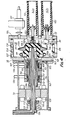
- a rotating anode x-ray tube has an evacuated envelope; a cathode and a rotatable anode within the envelope; and means for rotating the anode; characterised in that the anode comprises an insulating target support defining a chamber and an anode target carried by the support so as to face the cathode; a shaft rotatable with the target support has internal coolant channels for permitting coolant to flow into and out of the chamber and a bearing device with a vacuum seal around the shaft where it extends into the envelope.
- an evacuated envelope 101 is constructed with a metal housing 10 which, in use, is maintained at earth potential. Inside this envelope 101 is a cathode 20 which is fixed to the housing 10 via an insulator 102.
- the housing 10 is made from a central section 103, a voltage supply section 104 and a bearing section 105, which are connected to each other via 0-rings 106, 107 so as to be airtight.
- a shaft housing 110 is fitted to this bearing section 105 with bearings 108, 109.
- Inside bearing section 105 is fitted a magnet 11 which has been magnetised in the direction of the axle, and, at its ends, magnetic poles 112, 113 are attached to the bearing section via O-rings 114, 115.
- a magnetic fluid 116 is spread between magnetic poles 112, 113 and shaft housing 110, allowing free rotation between shaft housing 110 and magnetic poles 112, 113 with a vacuum seal (see U. S. Patent No. 4405876 [Iversen]).
- Shaft housing 110 is fixed to a shaft 118 with a central space section 117, and, with this central space section being a vacuum, the heat from the shaft is not readily transmitted to the magnetic fluid.
- the inner end of the cylinder of shaft housing 110 has a groove cut in it and is affixed with a nut 119.
- an 0-ring is attached by a clamp nut 120, working as a vacuum seal between shaft housing 110 and shaft 118.
- Shaft 118 is made of an electrical insulator with high thermal conductivity, and is an open-ended tube at the atmospheric end, but is closed at the other end, i.e., at a target support 118-a.
- a target 40 is attached concentrically to target support 118-a. Inside this target support 118-a there is a coolant chamber 118-b. Target support 118-a and, consequently, target 40 are cooled by the coolant in this coolant chamber 118-b. Even if the coolant used is an electrically conducting material, such as water for example, because the coolant and target 40 are electrically insulated, target 40 can be maintained at a different potential from the coolant, if required.
- Target 40 and target support 118-a may be forced together by nut 121 with a suitable flexible gasket (not shown), or may be fixed together by hot pressing, etc.
- a conductor 122 is fixed to the surface of target support 118-a and a protrusion made of a hard metal, such as SKH9 (JIS standard), is provided on the conductor at the centre of rotation.
- An electrical potential is applied to target 40 by contact between this protrusion and a contact 123 which is fixed to voltage supply section 104 of housing 10 via an insulated tube 124.
- corrugated section 118-c Between the bearing section of shaft 118 and the target support 118-a there is a corrugated section 118-c to lengthen the surface distance. Surrounding, and concentric to, this corrugated section 118-c there is a ring 125 preventing deterioration of the dielectric strength due to secondary electrons from the electron incident surface of target 40.
- An x-ray emission window 126 made of a material with a high x-ray transmission coefficient, such as beryllium for example, is fitted to housing 10.
- a material with a high x-ray transmission coefficient such as beryllium for example.
- Rotor 128 of the induction motor is fixed to shaft 118 and is rotated at high speed by the rotating magnetic field produced by a stator 70 which surrounds it. If a fan (not shown) is attached to rotor 128 or shaft 118, the motor will be self-cooled.
- Ring 130 is fixed to open end 118-d of shaft 118 via an 0-ring 129.
- a concentric cylinder 131 is attached around this ring 130 and a bushing 132 made of, for example, resin plastic is fitted between ring 130 and cylinder 131.
- a coolant seal 133 is fitted concentrically with ring 130 so that coolant does not leak to the outside.
- a tube 134 is fitted concentrically inside the shaft 118 and coolant is supplied from the outside to the coolant chamber 118-b through tube 134.
- Coolant channels 135, 136 inside bearing section 105 cooling the above-mentioned magnetic fluid 116.
- coolant channels 137, 138, 139 surrounding housing 10 to absorb the heat radiated by target 40.
- Stator 70 is fixed to housing 10 by a support cylinder 140.
- the coolant chamber 118-b is divided by partitions 118-e and the coolant flows separately into each of the coolant chambers 118-b.
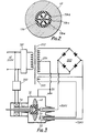
- 200V AC is converted to a high voltage by a high voltage transformer 202 through a primary controller 201 which includes a switch, and +75kV and - 75kV DC are obtained relative to neutral point 204 by means of a high voltage rectifier circuit 203.
- Neutral point 204 is earthed and connected to housing 10
- +75kV DC is supplied to target 40 through high voltage supply section 142a
- -75kV is supplied to cathode 20 through high voltage supply section 142b.
- the current at the electron generating filament 2a of cathode 20 is supplied separately from a secondary winding 205 in high voltage transformer 202.
- the electrons emitted by electron gun 30 are accelerated by the 150kV potential between target 40 and electron gun, and reach the surface of target 40.
- the high energy electron beam strikes a tungsten or tungsten alloy plate 40a which is attached to the surface of target 40.
- x-rays are generated at the surface.
- the heat generated at the same time is quickly transmitted to the middle of target 40 which is made of a heavy metal.
- the heat from target 40 is then transmitted to the coolant inside coolant chamber 118-b of shaft 118 which is made from an insulator with high thermal conductivity.
- the coolant, pushed by partitions 118-e rotates at high speed along with target 40, and is forced under great pressure against the inner walls of coolant chamber 118-b by the strong centrifugal force.
- coolant chamber 118-b If water is used as the coolant, then, since the internal surface of coolant chamber 118-b is normally kept below 120°C, normally heat is readily removed at a rate of around 4kW. By allowing a certain amount of heat, e.g. 500KHU, to remain in target 40, whilst keeping the surface
- a large momentary input power can be supplied by permitting a temperature rise in the electron incident track surface.
- the design temperature of the electron incident track surface is 500 C or less
- the size of the x-ray focus can be reduced to 0.67 times the size for the same x-ray output, greatly improving the resolution of x-ray diagnosis equipment.
- target 40 is kept at about +75kV, housing 10 at 0V and electron gun 30 at about -75kV, the rotating anode x-ray tube in this equipment can be used without any changes to existing x-ray equipment.
- Fig. 7 The existing design mentioned above (Fig.7) is fitted inside an x-ray tube envelope (not shown) for operation, but since the rotating anode x-ray tube in this invention can be used just as shown in Fig.l, it is smaller and lighter than the existing design.
- the embodiment in Fig.l has a total length of 42cm and a maximum diameter of 20cm.
- a variant of the embodiment has the connection between vacuum end 118-a of shaft 118 and target 40 made by metallizing the surface of 118-a, which is an insulator, and soldering the two components together. This is desirable because it improves the thermal conductivity.
- the height of partitions 118-e inside vacuum end 118-a of shaft 118 is the same as the internal diameter of shaft 118 in the embodiment, but may also be lower or higher. In addition, they may be completely omitted.
- tube 134 is fitted separately from shaft 118, but shaft 118 and tube 134 may be made as a single unit, or constructed so that tube 134 is supported by shaft 118, with shaft 118 and tube 134 being rotated together. in these cases, of course, a rotary joint (not shown) is necessary for part of tube 134.
- rotor 128 By treating the outer surface of shaft 118 from the shaft housing to the atmospheric end with a metallization process, rotor 128 can be kept at earth potential via bearings 108, 109 giving stable operation.
- shaft 118 and shaft housing 110 are fixed, if shaft 118 and one end of shaft housing 110 on the target side are tapered so as to fit together, and a vertical groove is cut into shaft housing 110 near to this joint to give it elasticity, this removes play when it expands due to the heat, and gives it just enough force to prevent the axle wobbling when it is rotating.
- a material with a spring action eg. a cylindrical spring
- Rotor 128 and shaft 118 may also be fitted together using the above method. It is of course possible to fit several electron guns 30.
- a heat exchanger may be fitted so that the coolant flows in a closed loop, and this heat exchanger may be cooled either by water or by forced air.
- high voltage supply section bushing 142a, 142b is parallel to the tube axis on the end of the vessel facing the rotating shaft, but if one or both of these is fitted perpendicular to the tube axis, it has the effect of reducing the total length of the tube.
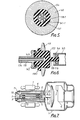
- Fig.4 shows another embodiment, wherein parts identical and corresponding to Fig.l are denoted with like reference numerals.
- This embodiment uses a tubular metal shaft 118A made from stainless steel or a similar material instead of the insulating shaft 118 of the embodiment in Fig.l.
- Shaft 118A has a large diameter cylinder 118A-a at the target 4 end, and holds a target support section 118-1 made of AlN.
- Target support section 118-1 takes the form of a tube with a closed bottom, and a chamber is formed between it and the large diameter cylinder 118A-a.
- the inner walls of target support section 118-1 chamber are covered with a metal layer 141.
- Tube 134 passes down the centre of shaft 118A, and ends in a chamber 118-1-a.
- the 2-way flow channel made by shaft 118A and tube 134 is continuous with chamber 118-1-a.
- a chamber 118-1-a is divided into several small chamber structures by metal plates 141-1 stretching from the metal layer 141 towards a tube 134.
- the metal shaft has the advantage of being easy to connect to other metal components. For example, breakdowns due to vacuum leaks, etc., can be prevented by a good connection with metal layer 141.
- shaft 118 alone can be made into a 2-way coolant channel.
- shaft 118 itself may be made into a 2- way coolant path by making lots of holes almost parallel to the axis and making another rotary seal around the holes in the central section on the outside of rotary seal 133.
- the joint between vacuum end 118-a of shaft 118 and anode target 40 may be made by metallizing the surface of 118-a which is made from an insulator, and then soldering them together, or by exchanging metal layer 141 for a thick metal cap and making it in advance as a single unit with shaft end section 118-a, or soldering to maintain a vacuum and then fitting insulating target support section 118-1. If this is done, there is no need for an air-tight seal between shaft 118 and target support section 118-1.
- Shaft 118-A and target support section 118-1 are tightly fixed mechanically by bolts 142. Between them there is an 0-ring forming a seal for the coolant. There is a projection 118-1-b on the end of target support section 118-1, with an electrically conducting material attached to its surface. A ball bearing 144 is fitted in contact with this. This bearing reduces friction in the vacuum using a solid lubricant. Bearing 144 is supported by support tube 145, and this support tube 145 is fixed to the voltage supply section 104 of the housing via insulating tube 124. A high voltage is then supplied to anode target 40 through the above-mentioned metal layer 122, bearing 144 and support tube 145.
- the anode target 40 may also be cooled by constructing a heat pipe inside shaft 118A, and cooling the section of shaft 118 which is outside the vacuum.
Landscapes
- X-Ray Techniques (AREA)
Applications Claiming Priority (4)
| Application Number | Priority Date | Filing Date | Title |
|---|---|---|---|
| JP59204808A JPS6182642A (ja) | 1984-09-29 | 1984-09-29 | 回転陽極型x線管 |
| JP204808/84 | 1984-09-29 | ||
| JP59278428A JPS61151956A (ja) | 1984-12-25 | 1984-12-25 | 回転陽極型x線管 |
| JP278428/84 | 1984-12-25 |
Publications (3)
| Publication Number | Publication Date |
|---|---|
| EP0186937A2 true EP0186937A2 (fr) | 1986-07-09 |
| EP0186937A3 EP0186937A3 (en) | 1987-11-25 |
| EP0186937B1 EP0186937B1 (fr) | 1990-12-27 |
Family
ID=26514679
Family Applications (1)
| Application Number | Title | Priority Date | Filing Date |
|---|---|---|---|
| EP85306929A Expired - Lifetime EP0186937B1 (fr) | 1984-09-29 | 1985-09-27 | Tube à rayons X à anode rotative |
Country Status (3)
| Country | Link |
|---|---|
| US (1) | US4674109A (fr) |
| EP (1) | EP0186937B1 (fr) |
| DE (1) | DE3581181D1 (fr) |
Cited By (6)
| Publication number | Priority date | Publication date | Assignee | Title |
|---|---|---|---|---|
| FR2644289A1 (fr) * | 1989-03-07 | 1990-09-14 | Mecanique Magnetique Sa | Tube a rayons x a anode tournante suspendue par paliers magnetiques actifs et refroidie par circulation de fluide |
| EP0502216A1 (fr) * | 1990-09-27 | 1992-09-09 | Fanuc Ltd. | Dispositif refroidisseur pour element rotatif |
| EP0576258A2 (fr) * | 1992-06-22 | 1993-12-29 | Ferrofluidics Corporation | Joint à ferrofluide à pompage différentiel |
| EP0665574A1 (fr) * | 1994-01-28 | 1995-08-02 | Rigaku Corporation | Tube à rayons X à anode tournante |
| EP4243051A1 (fr) * | 2022-03-08 | 2023-09-13 | Koninklijke Philips N.V. | Source de rayons x à anode rotative |
| WO2023169908A1 (fr) * | 2022-03-08 | 2023-09-14 | Koninklijke Philips N.V. | Source de rayons x à anode rotative |
Families Citing this family (32)
| Publication number | Priority date | Publication date | Assignee | Title |
|---|---|---|---|---|
| DE8615918U1 (de) * | 1986-06-13 | 1987-10-15 | Siemens AG, 1000 Berlin und 8000 München | Flüssigkeitsgekühlter Röntgenstrahler mit einer Umlaufkühleinrichtung |
| US4912739A (en) * | 1987-09-21 | 1990-03-27 | Weiss Mortimer E | Rotating anode X-ray tube with deflected electron beam |
| US4964148A (en) * | 1987-11-30 | 1990-10-16 | Meicor, Inc. | Air cooled metal ceramic x-ray tube construction |
| DE4227495A1 (de) * | 1992-08-20 | 1994-02-24 | Philips Patentverwaltung | Drehanoden-Röntgenröhre mit Kühlvorrichtung |
| US5784430A (en) * | 1996-04-16 | 1998-07-21 | Northrop Grumman Corporation | Multiple station gamma ray absorption contraband detection system |
| US6011829A (en) * | 1998-02-20 | 2000-01-04 | Picker International, Inc. | Liquid cooled bearing assembly for x-ray tubes |
| US6215851B1 (en) | 1998-07-22 | 2001-04-10 | Northrop Grumman Corporation | High current proton beam target |
| US6249569B1 (en) | 1998-12-22 | 2001-06-19 | General Electric Company | X-ray tube having increased cooling capabilities |
| US6335512B1 (en) | 1999-07-13 | 2002-01-01 | General Electric Company | X-ray device comprising a crack resistant weld |
| US6252937B1 (en) * | 1999-09-14 | 2001-06-26 | General Electric Company | High thermal performance cathode via heat pipes |
| US6385293B1 (en) * | 2000-02-10 | 2002-05-07 | Philips Medical Systems (Cleveland), Inc. | Thermally equalized X-ray tube bearing |
| US6445770B1 (en) | 2000-02-10 | 2002-09-03 | Koninklijke Philips Electronics N.V. | Thermally isolated x-ray tube bearing |
| US6453010B1 (en) | 2000-06-13 | 2002-09-17 | Koninklijke Philips Electronics N.V. | X-ray tube liquid flux director |
| US6477231B2 (en) * | 2000-12-29 | 2002-11-05 | General Electric Company | Thermal energy transfer device and x-ray tubes and x-ray systems incorporating same |
| US6430260B1 (en) | 2000-12-29 | 2002-08-06 | General Electric Company | X-ray tube anode cooling device and systems incorporating same |
| US6377659B1 (en) | 2000-12-29 | 2002-04-23 | Ge Medical Systems Global Technology Company, Llc | X-ray tubes and x-ray systems having a thermal gradient device |
| US6707882B2 (en) | 2001-11-14 | 2004-03-16 | Koninklijke Philips Electronics, N.V. | X-ray tube heat barrier |
| US6781060B2 (en) * | 2002-07-26 | 2004-08-24 | X-Ray Optical Systems Incorporated | Electrical connector, a cable sleeve, and a method for fabricating an electrical connection |
| AU2002357069A1 (en) * | 2001-12-04 | 2003-06-17 | X-Ray Optical Systems, Inc. | Method and device for cooling and electrically insulating a high-voltage, heat-generating component such as an x-ray tube |
| US7382856B2 (en) * | 2001-12-04 | 2008-06-03 | X-Ray Optical Systems, Inc. | X-ray source assembly having enhanced output stability, and fluid stream analysis applications thereof |
| US6778635B1 (en) | 2002-01-10 | 2004-08-17 | Varian Medical Systems, Inc. | X-ray tube cooling system |
| WO2004023852A2 (fr) * | 2002-09-03 | 2004-03-18 | Parker Medical, Inc. | Generateur de rayons x a rainures multiples |
| US6940947B1 (en) | 2002-09-05 | 2005-09-06 | Varian Medical Systems Technologies, Inc. | Integrated bearing assembly |
| EP1661439A2 (fr) * | 2003-08-04 | 2006-05-31 | X-Ray Optical Systems, Inc. | Ensemble source de rayons x a stabilite de sortie amelioree a l'aide de reglages de puissance de tubes et a etalonnage a distance |
| DE10353964B4 (de) * | 2003-11-19 | 2013-10-10 | Siemens Aktiengesellschaft | Röntgenröhre mit Drehanode |
| US7338049B2 (en) * | 2004-08-26 | 2008-03-04 | Ferrotec (Usa) Corporation | Self-cooling ferrfluid seal |
| FR2879807B1 (fr) * | 2004-12-21 | 2007-02-23 | Gen Electric | Tube a rayons x a palier perfectionne et procede de fabrication |
| WO2013174436A1 (fr) * | 2012-05-24 | 2013-11-28 | Quantum Technologie Gmbh | Anode rotative refroidie pour tube à rayons x |
| DE102014204112A1 (de) * | 2014-03-06 | 2015-09-10 | Siemens Aktiengesellschaft | Röntgenröhre |
| JP6677420B2 (ja) * | 2016-04-01 | 2020-04-08 | キヤノン電子管デバイス株式会社 | X線管装置 |
| CN111243924B (zh) * | 2020-01-14 | 2022-10-25 | 中国电子科技集团公司第三十八研究所 | 一种用于射线源的转动靶机构 |
| FR3113540A1 (fr) * | 2020-08-20 | 2022-02-25 | William VACHER | Dispositif de génération d’un rayonnement électromagnétique cohérent |
Citations (5)
| Publication number | Priority date | Publication date | Assignee | Title |
|---|---|---|---|---|
| DE2058152A1 (de) * | 1970-11-26 | 1972-05-31 | Siemens Ag | Drehanoden-Roentgenroehre |
| FR2338578A1 (fr) * | 1976-01-16 | 1977-08-12 | Philips Nv | Tube de rontgen a anode rotative supportee par voie magnetique |
| US4165472A (en) * | 1978-05-12 | 1979-08-21 | Rockwell International Corporation | Rotating anode x-ray source and cooling technique therefor |
| JPS56141153A (en) * | 1980-04-03 | 1981-11-04 | Toshiba Corp | Target for x-ray tube |
| FR2484698A1 (fr) * | 1980-06-16 | 1981-12-18 | Siemens Ag | Tube a rayons x a anode tournante |
Family Cites Families (3)
| Publication number | Priority date | Publication date | Assignee | Title |
|---|---|---|---|---|
| GB854363A (en) * | 1956-02-20 | 1960-11-16 | Nat Res Dev | Improvements in x-ray tubes with rotating anodes |
| DE2711847C2 (de) * | 1977-03-18 | 1979-03-22 | Kernforschungsanlage Juelich Gmbh, 5170 Juelich | Röntgenröhre |
| US4405876A (en) * | 1981-04-02 | 1983-09-20 | Iversen Arthur H | Liquid cooled anode x-ray tubes |
-
1985
- 1985-09-26 US US06/780,176 patent/US4674109A/en not_active Expired - Fee Related
- 1985-09-27 DE DE8585306929T patent/DE3581181D1/de not_active Expired - Lifetime
- 1985-09-27 EP EP85306929A patent/EP0186937B1/fr not_active Expired - Lifetime
Patent Citations (5)
| Publication number | Priority date | Publication date | Assignee | Title |
|---|---|---|---|---|
| DE2058152A1 (de) * | 1970-11-26 | 1972-05-31 | Siemens Ag | Drehanoden-Roentgenroehre |
| FR2338578A1 (fr) * | 1976-01-16 | 1977-08-12 | Philips Nv | Tube de rontgen a anode rotative supportee par voie magnetique |
| US4165472A (en) * | 1978-05-12 | 1979-08-21 | Rockwell International Corporation | Rotating anode x-ray source and cooling technique therefor |
| JPS56141153A (en) * | 1980-04-03 | 1981-11-04 | Toshiba Corp | Target for x-ray tube |
| FR2484698A1 (fr) * | 1980-06-16 | 1981-12-18 | Siemens Ag | Tube a rayons x a anode tournante |
Non-Patent Citations (1)
| Title |
|---|
| PATENT ABSTRACTS OF JAPAN, vol. 6, no. 21 (E-93)[899], 6th February 1982; & JP-A-56 141 153 (TOKYO SHIBAURA DENKI K.K.) 04-11-1981 * |
Cited By (9)
| Publication number | Priority date | Publication date | Assignee | Title |
|---|---|---|---|---|
| FR2644289A1 (fr) * | 1989-03-07 | 1990-09-14 | Mecanique Magnetique Sa | Tube a rayons x a anode tournante suspendue par paliers magnetiques actifs et refroidie par circulation de fluide |
| EP0502216A1 (fr) * | 1990-09-27 | 1992-09-09 | Fanuc Ltd. | Dispositif refroidisseur pour element rotatif |
| EP0502216A4 (en) * | 1990-09-27 | 1993-03-31 | Fanuc Ltd. | Cooling device of rotating member |
| EP0576258A2 (fr) * | 1992-06-22 | 1993-12-29 | Ferrofluidics Corporation | Joint à ferrofluide à pompage différentiel |
| EP0576258A3 (fr) * | 1992-06-22 | 1994-08-03 | Ferrofluidics Corp | |
| EP0665574A1 (fr) * | 1994-01-28 | 1995-08-02 | Rigaku Corporation | Tube à rayons X à anode tournante |
| US5579364A (en) * | 1994-01-28 | 1996-11-26 | Rigaku Corporation | Rotating-anode X-ray tube |
| EP4243051A1 (fr) * | 2022-03-08 | 2023-09-13 | Koninklijke Philips N.V. | Source de rayons x à anode rotative |
| WO2023169908A1 (fr) * | 2022-03-08 | 2023-09-14 | Koninklijke Philips N.V. | Source de rayons x à anode rotative |
Also Published As
| Publication number | Publication date |
|---|---|
| EP0186937B1 (fr) | 1990-12-27 |
| US4674109A (en) | 1987-06-16 |
| DE3581181D1 (de) | 1991-02-07 |
| EP0186937A3 (en) | 1987-11-25 |
Similar Documents
| Publication | Publication Date | Title |
|---|---|---|
| EP0186937B1 (fr) | Tube à rayons X à anode rotative | |
| US5438605A (en) | Ring tube x-ray source with active vacuum pumping | |
| US4993055A (en) | Rotating X-ray tube with external bearings | |
| EP0564293B1 (fr) | Source à rayons X annulaire | |
| US7558376B2 (en) | Rotating anode X-ray tube assembly | |
| US7515687B2 (en) | Compact source with very bright X-ray beam | |
| US4878235A (en) | High intensity x-ray source using bellows | |
| US6327340B1 (en) | Cooled x-ray tube and method of operation | |
| JP2002334675A (ja) | 温度勾配デバイスを有するx線管とx線システム | |
| US6364527B1 (en) | Rotating bulb x-ray radiator | |
| US6445769B1 (en) | Internal bearing cooling using forced air | |
| JP2006179482A (ja) | 冷却式放射線放出デバイス | |
| US6570960B1 (en) | High voltage isolated rotor drive for rotating anode x-ray tube | |
| JP4309290B2 (ja) | X線ターゲット用液体金属ヒートパイプ構造 | |
| CN112928003A (zh) | X射线发生装置及成像设备 | |
| JP4526113B2 (ja) | マイクロフォーカスx線管及びそれを用いたx線装置 | |
| JP2012238506A (ja) | 回転陽極型x線管装置 | |
| JP7491756B2 (ja) | 回転陽極型x線管装置およびx線撮像装置 | |
| JP2726252B2 (ja) | X線管 | |
| US2121632A (en) | X-ray tube | |
| JP3030069B2 (ja) | X線管 | |
| JPH0334183B2 (fr) | ||
| US5708695A (en) | Electrical coupling of rotating members of medical imaging devices | |
| JPS6182643A (ja) | 回転陽極型x線管 | |
| US6453011B1 (en) | X-ray tube with rotating anode core |
Legal Events
| Date | Code | Title | Description |
|---|---|---|---|
| PUAI | Public reference made under article 153(3) epc to a published international application that has entered the european phase |
Free format text: ORIGINAL CODE: 0009012 |
|
| 17P | Request for examination filed |
Effective date: 19851018 |
|
| AK | Designated contracting states |
Kind code of ref document: A2 Designated state(s): DE FR GB |
|
| PUAL | Search report despatched |
Free format text: ORIGINAL CODE: 0009013 |
|
| AK | Designated contracting states |
Kind code of ref document: A3 Designated state(s): DE FR GB |
|
| 17Q | First examination report despatched |
Effective date: 19890628 |
|
| GRAA | (expected) grant |
Free format text: ORIGINAL CODE: 0009210 |
|
| AK | Designated contracting states |
Kind code of ref document: B1 Designated state(s): DE FR GB |
|
| REF | Corresponds to: |
Ref document number: 3581181 Country of ref document: DE Date of ref document: 19910207 |
|
| ET | Fr: translation filed | ||
| PLBE | No opposition filed within time limit |
Free format text: ORIGINAL CODE: 0009261 |
|
| STAA | Information on the status of an ep patent application or granted ep patent |
Free format text: STATUS: NO OPPOSITION FILED WITHIN TIME LIMIT |
|
| 26N | No opposition filed | ||
| PGFP | Annual fee paid to national office [announced via postgrant information from national office to epo] |
Ref country code: GB Payment date: 19960918 Year of fee payment: 12 |
|
| PGFP | Annual fee paid to national office [announced via postgrant information from national office to epo] |
Ref country code: DE Payment date: 19961004 Year of fee payment: 12 |
|
| PG25 | Lapsed in a contracting state [announced via postgrant information from national office to epo] |
Ref country code: GB Free format text: LAPSE BECAUSE OF NON-PAYMENT OF DUE FEES Effective date: 19970927 |
|
| GBPC | Gb: european patent ceased through non-payment of renewal fee |
Effective date: 19970927 |
|
| PG25 | Lapsed in a contracting state [announced via postgrant information from national office to epo] |
Ref country code: DE Free format text: LAPSE BECAUSE OF NON-PAYMENT OF DUE FEES Effective date: 19980603 |
|
| REG | Reference to a national code |
Ref country code: FR Ref legal event code: D6 |
|
| PGFP | Annual fee paid to national office [announced via postgrant information from national office to epo] |
Ref country code: FR Payment date: 20000912 Year of fee payment: 16 |
|
| PG25 | Lapsed in a contracting state [announced via postgrant information from national office to epo] |
Ref country code: FR Free format text: LAPSE BECAUSE OF NON-PAYMENT OF DUE FEES Effective date: 20020531 |
|
| REG | Reference to a national code |
Ref country code: FR Ref legal event code: ST |