EP0186761A2 - Einstellbare Wehrplatte für Vollmantel-Schneckenzentrifugen - Google Patents
Einstellbare Wehrplatte für Vollmantel-Schneckenzentrifugen Download PDFInfo
- Publication number
- EP0186761A2 EP0186761A2 EP85114275A EP85114275A EP0186761A2 EP 0186761 A2 EP0186761 A2 EP 0186761A2 EP 85114275 A EP85114275 A EP 85114275A EP 85114275 A EP85114275 A EP 85114275A EP 0186761 A2 EP0186761 A2 EP 0186761A2
- Authority
- EP
- European Patent Office
- Prior art keywords
- weir
- weir plate
- axis
- plate according
- screw
- Prior art date
- Legal status (The legal status is an assumption and is not a legal conclusion. Google has not performed a legal analysis and makes no representation as to the accuracy of the status listed.)
- Granted
Links
Images

Classifications
-
- B—PERFORMING OPERATIONS; TRANSPORTING
- B04—CENTRIFUGAL APPARATUS OR MACHINES FOR CARRYING-OUT PHYSICAL OR CHEMICAL PROCESSES
- B04B—CENTRIFUGES
- B04B1/00—Centrifuges with rotary bowls provided with solid jackets for separating predominantly liquid mixtures with or without solid particles
- B04B1/20—Centrifuges with rotary bowls provided with solid jackets for separating predominantly liquid mixtures with or without solid particles discharging solid particles from the bowl by a conveying screw coaxial with the bowl axis and rotating relatively to the bowl
- B04B2001/2083—Configuration of liquid outlets
Definitions
- the invention relates to an adjustable weir plate for solid bowl screw centrifuges with the features of the preamble of claim 1.
- Solid-bowl screw centrifuges of the type in question are used, among other things, for very difficult separation tasks that require a very precise adjustment of the pond height in the centrifuge separation area through a finely variable weir adjustment for the liquid drain in order to achieve optimal separation results, for example in the area of sludge that is difficult to convey. But there is also a need to make the weir height adjustable.
- weir plates which can be variably adjusted have been used, in such a way that they have a plurality of bores in their side areas through which the two fixing screws are guided, depending on the choice of the radial position of the plate and thus the weir diameter.
- These plate sets must be made available, kept in stock and used in the correct assignment, which requires a correspondingly large amount of effort.
- weir plates which are round with respect to the outer circumference and which have a bore arranged eccentrically to the outer circumference, through which the liquid phase is discharged.
- These weir plates can be fixed in different rotational positions at a distance from bores arranged in the peripheral side area, so that correspondingly different spacing positions the bores are adjustable to the axis of rotation of the centrifuge.
- the diameter of the eccentric bores within the weir disks is relatively small compared to that of the drain openings, which adversely affects the amount of liquid that can be removed per unit of time. When the throughput changes, the weir accumulates at different heights. This is contrary to the exact weir setting desired.
- the size and / or number of the drain openings in the jacket cover of the centrifuge is limited for reasons of strength.
- weir-shaped weir disks the boundary of which extends outside the circular circumference and serves as an overflow edge which extends over the opening width of the drain opening and is curved to follow the circumferential path of the weir diameter formed by it.
- a separate set of weir plates is required for each of the weir diameters to be set.
- the invention has for its object to provide a weir plate of the type mentioned which, after manufacture, handling and warehousing, enables a fine-stage weir height adjustment over a large diameter range in the most cost-effective and simple manner.
- the displaceability of the weir plate according to the invention in the radial direction to the centrifuge axis by means of a rotatably mounted adjusting member and the fixing in the respectively set position makes it possible to use one and the other the same weir plate per drain opening to set a large number of finely spaced weir diameters, the overflow edge of which extends over the width of the drain opening, so that its drainage capacity is fully utilized.
- the adjusting member can be designed as a lever, the fulcrum of which is fixed to the jacket cover and the pivotable end of which engages on an attack surface of the weir plate or vice versa.
- a lever or the like is sufficient, it being possible to ensure the correct position of the overflow edge by sliding the weir plate.
- the lever is designed as an eccentric disc, which is further preferably inserted into a circular recess in the weir plate.
- two such eccentric discs are provided, the axes of rotation of which are formed by the fastening screws for the weir plate. There is a screw in each side area of the weir plate.
- the individual settings - in particular staggered at a distance of 1 mm - the weir diameter are fixed by markings of the position of rotation for the setting member, in particular by positive engagement designs, for example in the manner of tongue and groove. This enables the weir diameter to be set absolutely the same for all weir plates, which is important for the exact sequence and balancing of the centrifuge.
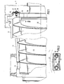
- the centrifuge 1 consists of a cylindrical section - on the right in the picture - which merges to the left into a conical section, a central section with the transition being omitted.
- the screw 12 Inside the jacket 11 of the centrifuge, the screw 12 is arranged, the outer contour of which is adapted to the inner wall of the jacket 11.
- the centrifuge is operated at high revolutions, whereby gear measures, not shown, ensure that the screw 12 rotates at a low differential speed relative to the casing 11, such that, due to the centrifugal force, solid settling on the inner wall of the casing is a non-illustrated in the Separation chamber 14 continuously fed suspension is transported from the screw spiral to the solid discharge 13 in the end region of the conical section of the centrifuge.
- the liquid phase of the suspension which clears due to the higher specific weight of the solid, is therefore present in the radially innermost area of the suspension pond in the separation chamber, with an optimum separation result depending on the type of suspension - separation quality and separation throughput - with the parallel dimension of the pond in Separation space is dependent.
- the radial dimension pond determined by adjustable weir p la tt s, which are set in the range of drain openings 15 in the shell cover 16.
- adjustable weir p la tt s which are set in the range of drain openings 15 in the shell cover 16.
- the drainage openings 15 are arranged distributed over the circumference of the cover, their number and / or their opening width is limited by the strength requirements of the cover.
- a radially outer portion of the drain openings 15 is covered by weir plates 17, which are held by screws 18 and adjustable by adjusting members 19 in a manner to be described in more detail with regard to their distance from the axis of rotation 20 of the centrifuge.
- the overflow edge 21 or 22 of the weir plates facing the centrifuge axis 20 determines the weir diameter and thus the radial thickness of the suspension pond which forms a cylindrical shape in rotation in the separating space 14.
- the overflow edges 21 and 22 are approximately the circumferential profile of the circular arc determined by an average weir diameter subsequently curved, as can be seen in FIG. 2.
- the setting of different weir diameters is described using an exemplary embodiment of the weir plate 17 for one of the drain openings 15, each of which is assigned a corresponding weir plate.
- the adjusting members 19 each have a circular outer circumference and thus a circular cylindrical circumferential surface around the central axis 23, which is offset eccentrically from the parallel screw axis 24 of the associated screw 18 by the distance e.
- the weir plate 17 has a plate recess 27 for the two adjusting members 19 designed as eccentric disks and the associated screws 18, which as seen from the insertion side of the screw 18 as section 29 with a circular cylinder
- the inner circumferential surface 25 is formed around the center axis 23 of the adjusting member 19 inserted in the section 29, the circumferential surface 26 of the adjusting member 19 abutting against the inner circumferential surface of the portion 29 serving as the engagement surface 25 with a clearance fit.
- a pivot bearing bore 28 is made in the adjusting member 19, which with a clearance fit accommodates a cylindrical section of the screw bolt below the screw head of the screw 18.
- an opening region 31 is introduced into the bottom of the section 29 of the plate recess 27, which has a smaller diameter than the section 29 and through which the shaft of the screw 18 is guided in order to thread into the side of the drain opening 15 to be screwed into the jacket cover 16 and thus to fix the weir plate 17 thereon.
- a shoulder 30 against which or the surface 32 of which the setting member 19 acted upon by the screw 18 in the fixed state is held.
- the opening region 31 of the plate recess 27 is held so far that the weir plate can move around the shaft of the screw 18 in any possible rotational position setting of the adjusting member and thus corresponding radial displacement.
- the screw shaft is so long that the screw can be loosened so far without leaving the thread that the adjusting member 19 can be removed from its engagement in the section 29 and reinserted in a different rotational position.
- the setting members 19 can be inserted in specific, precisely positioned positions of rotation, marked by form-fitting engagement, in the respectively associated section 29 of the plate recess 27, as in particular 3 shows.
- the form-fitting engagement formation is made here in such a way that in the circumferential area of the adjusting members 19 parallel to the center axis 23, radially outwardly open in cross-section approximately semi-circular recesses 33 are incorporated, which interrupt the circumferential surface 26, while on the inner circumferential surface 25 of section 29 of the plate recess 27, a correspondingly approximately semicircular projection is provided, which engages in one of the cutouts 33 either selectively or depending on the rotational position of the setting member 19.
- this projection is formed by approximately one longitudinal half of a pin 34, for example in the form of a grooved pin, which is inserted parallel to the center axis 23 into a bore made in the transition between the heel area 30 and the inner peripheral surface 25, which is aligned in one approximately semicircular recess 40 runs out, which lies parallel to the center axis 23 in the inner peripheral surface 25 of the section 29.
- ⁇ is the angle about the center axis 23 of the adjusting members 19, under which a recess 33 is arranged, which belongs to a certain gradation Ar.
- the even-numbered recesses 2, 4, 6, 8 are arranged on one half 37 of the circumference and the odd-numbered recesses 1, 3, 5, 7, 9 on the other circumferential half 36 of the adjusting members 19, while the recesses 0 and 10 are approximately in Weir radius direction.
Landscapes
- Centrifugal Separators (AREA)
Abstract
Description
- Die Erfindung bezieht sich auf eine einstellbare Wehrplatte für Vollmantel-Schneckenzentrifugen mit den Merkmalen des Oberbegriffes des Anspruches 1.
- Vollmantel-Schneckenzentrifugen der in Frage stehenden Art werden unter anderem für sehr diffizile Trennaufgaben eingesetzt, die ein sehr genaues Einstellen der Teichhöhe im Zentrifugentrennraum durch eine feinstufig veränderliche Wehreinstellung für den Flüssigkeitsablauf verlangen, um optimale Trennergebnisse zu erzielen, so beispielsweise im Gebiet der schwerförderbaren Schlämme. Aber auch sonst besteht ein Bedürfnis, die Wehrhöhe einstellbar zu gestalten.
- Zu diesem Zweck hat man bereits veränderlich einstellbare Wehrplatten verwendet, dergestalt, daß diese in ihren Seitenbereichen mehrere Bohrungen aufweisen, durch die je nach Wahl der radialen Lage der Platte und damit des Wehrdurchmessers die beiden Bestigungsschrauben geführt werden. Damit lassen sich jedoch nur verhältnismäßig grobe Wehrdurchmesseränderungen einstellen, so daß für eine feinstufige Einstellbarkeit des Wehrdurchmessers mehrere - für einen Einstellbereich von 20 mm in 1 mm-Schritten zehn - Wehrplattensätze erforderlich sind. Diese Plattensätze müssen zur Verfügung gestellt, auf Lager gehalten und in richtiger Zuordnung angewendet werden, was einen entsprechend großen Aufwand erfordert.
- Weiterhin ist bekannt, die Ablauföffnungen mit hinsichtlich des Außenumfanges runden Wehrplatten abzudecken, die eine exzentrisch zum Außenumfang angeordnete Bohrung aufweisen, durch die die Flüssigphase abgeführt wird. Diese Wehrplatten lassen sich im Abstand von im Umfangsseitenbereich angeordneten Bohrungen in unterschiedlichen Verdrehlagen festlegen, so daß entsprechend unterschiedliche Abstandslagen der Bohrungen zur Rotationsachse der Zentrifuge einstellbar sind. Der Durchmesser der exzentrischen Bohrungen innerhalb der Wehrscheiben ist im Vergleich zu demjenigen der Ablauföffnungen verhältnismäßig klein, was die abführbare Flüssigkeitsmenge pro Zeiteinheit nachteilig beeinträchtigt. Bei wechselndem Durchsatz staut das Wehr daher unterschiedlich hoch an. Dies steht der erstrebten exakten Wehreinstellung entgegen. Die Größe und/oder Anzahl der Ablauföffnungen in dem Manteldeckel der Zentrifuge ist aus Festigkeitsgründen beschränkt.
- Anstelle der vorgeschilderten runden Wehrplatten mit exzentrischer Bohrung ist es weiterhin bekannt, kreisabschnittförmige Wehrscheiben einzusetzen, deren außerhalb des kreisförmigen Umfanges verlaufende Begrenzung als Überlaufkante dient, die sich über die Öffnungsweite der Ablauföffnung erstreckt und der Umfangsbahn des durch sie gebildeten Wehrdurchmessers folgend gewölbt gestaltet ist. In diesem Falle braucht man für jeden der einzustellenden Wehrdurchmesser einen gesonderten Satz von Wehrplatten.
- Der Erfindung liegt die Aufgabe zugrunde, eine Wehrplatte der eingangs genannten Art zu schaffen, die nach Herstellung, Handhabung und Lagerhaltung in möglichst kostengünstiger und einfacher Weise eine feinstufige Wehrhöheneinstellung über einen großen Durchmesserbereich hinweg ermöglicht.
- Ausgehend von einer einstellbaren Wehrplatte mit den Merkmalen des Oberbegriffes des Anspruches 1 wird diese Aufgabe erfindungsgemäß durch dessen kennzeichnende Merkmale gelöst.
- Durch die erfindungsgemäße Versetzbarkeit der Wehrplatte in radialer Richtung zur Zentrifugenachse durch ein drehbar gelagertes Einstellglied und die Festlegung in der jeweilig eingestellten Lage wird es möglich, mit ein und derselben Wehrplatte pro Ablauföffnung eine Vielzahl feinstufig voneinander beabstandeter Wehrdurchmesser einzustellen, deren Überlaufkante die Weite der Ablauföffnung übergreift, so daß deren Ablaufkapazität voll ausgenutzt wird.
- Das Einstellglied kann als Hebel ausgebildet sein, dessen Drehpunkt an dem Manteldeckel festgelegt ist und dessen verschwenkbares Ende an einer Angriffsfläche der Wehrplatte angreift oder umgekehrt. Es reicht grundsätzlich ein Hebel oder dergleichen aus, wobei man durch eine Verschiebeführung der Wehrplatte die einwandfreie Lage der Überlaufkante sicherstellen kann.
- In besonders bevorzugter Ausführung ist der Hebel als Exzenterscheibe ausgebildet, die weiterhin vorzugsweise in eine kreisförmige Ausnehmung der Wehrplatte eingesetzt ist. Insbesondere sind zwei solcher Exzenterscheiben vorgesehen, deren Drehachsen durch die Befestigungsschrauben für die Wehrplatte gebildet sind. Dabei befindet sich in jedem Seitenbereich der Wehrplatte eine Schraube.
- In weiterhin bevorzugter Ausführung sind die einzelnen Einstellungen - insbesondere im Abstand von lmm gestaffelt - der Wehrdurchmesser durch Verdrehlagenmarkierung für das Einstellglied fixiert, insbesondere durch formschlüssige Eingriffsausbildungen, beispielsweise nach Art von Nut und Feder. Damit erreicht man eine absolut gleiche Wehrdurchmessereinstellung für alle Wehrplatten, was für den exakten Ablauf und die Auswuchtung der Zentrifuge von Bedeutung ist.
- Bevorzugte Ausführungen und weitere Ausgestaltungen der Erfindung ergeben sich aus den Unteransprüchen und im Zusammenhang mit dem in der Zeichnung wiedergegebenen Ausführungsbeispiel, dessen nachfolgende Beschreibung die Erfindung näher erläutert. Es zeigen:
- Fig. 1 eine schematisierte, in Längsrichtung unterbrochen wiedergegebene Teilansicht einer Zentrifuge der infrage stehenden Art mit einer Wehrplatte als Ausführungsbeispiel;
- Fig. 2 eine vergrößerte Teildraufsicht auf den Manteldeckel im Bereich einer Wehrplatte in Richtung des Pfeiles X in Fig. 1;
- Fig. 3 eine Draufsicht auf die Wehrplatte;
- Fig. 4 eine Schnittansicht durch die Wehrplatte nach der Linie IV-IV in Fig. 3 mit angrenzendem Bereich des Manteldeckels.
- Die Vollmantel-Schneckenzentrifuge gemäß Fig. 1 besteht aus einem zylindrischen Abschnitt - rechts im Bild - der nach links hin in einen konischen Abschnitt übergeht, wobei ein Mittelabschnitt mit dem Übergang weggelassen ist. Innerhalb des Mantels 11 der Zentrifuge ist die Schnecke 12 angeordnet, deren Außenkontur an die Innenwandung des Mantels 11 angepaßt ist. Die Zentrifuge wird mit hohen Umdrehungszahlen betrieben, wobei durch nicht dargestellte Getriebemaßnahmen dafür gesorgt ist, daß die Schnecke 12 sich mit geringer Differenzdrehzahl relativ zum Mantel 11 dreht, derart, daß aufgrund der Fliehkraft sich an der Mantelinnenwand absetzender Feststoff einer in nicht dargestellter Weise in den Trennraum 14 kontinuierlich eingespeisten Suspension von der Schneckenwendel zu dem Feststoffaustrag 13 im Endbereich des konischen Abschnittes der Zentrifuge transportiert wird. Die sich aufgrund des höheren spezifischen Gewichtes des Feststoffes klärende Flüssigphase der Suspension ist demnach im radial innersten Bereich des in dem Trennraum vorhandenen Suspensionsteiches vorhanden, wobei je nach Art der Suspension ein Optimum an Trennergebnis - Trenngüte und Trenndurchsatz - mit von der parallelen Abmessung des Teiches im Trennraum abhängig ist. Um dieses Optimum einstellen zu können, wird die radiale Teichabmessung durch einstellbare Wehrplatten bestimmt, die im Bereich von Ablauföffnungen 15 in dem Manteldeckel 16 als stirnseitiger Abschluß des zylindrischen Mantelteils an diesem festgelegt sind. Von den Ablauföffnungen 15 sind mehrere über den Umfang des Deckels verteilt angeordnete vorgesehen, ihre Zahl und/oder ihre Öffnungsweite ist durch die Festigkeitserfordernisse des Deckels nach oben begrenzt.
- Wie Fig..1 erkennen läßt, wird ein radial äußerer Abschnitt der Ablauföffnungen 15 von Wehrplatten 17 abgedeckt, die durch Schrauben 18 gehalten und durch Einstellglieder 19 in noch näher zu schildernder Weise hinsichtlich ihres Abstandes zu der Rotationsachse 20 der Zentrifuge einstellbar sind. Dabei bestimmt die der Zentrifugenachse 20 zugewandte Überlaufkante 21 bzw. 22 der Wehrplatten den Wehrdurchmesser und damit die radiale Mächtigkeit des sich bei Rotation zylinderförmig ausbildenden Suspensionsteiches im Trennraum 14. Dabei sind die Überlaufkanten 21 bzw. 22 etwa dem Umfangsverlauf des durch einen mittleren Wehrdurchmessers bestimmten Kreisbogens folgend gewölbt ausgebildet, wie dies Fig. 2 erkennen läßt.
- Anhand der Fig. 3 und 4 wird das Einstellen unterschiedlicher Wehrdurchmesser anhand eines Ausführungsbeispieles der Wehrplatte 17 für eine der Ablauföffnungen 15 geschildert, deren jeder eine entsprechende Wehrplatte zugeordnet ist. Die Einstellglieder 19 haben jeweils kreisrunden Außenumfang und damit eine kreiszylindrische Umfangsfläche um die Zentrumsachse 23 herum, der gegenüber die parallel verlaufende Schraubenachse 24 der zugehörigen Schraube 18 um den Abstand e exzentrisch versetzt ist. Die Wehrplatte 17 weist für die beiden als Exzenterscheiben ausgebildeten Einstellglieder 19 und die zugehörigen Schrauben 18 jeweils eine Plattenausnehmung 27 auf, die von der Einführseite der Schraube 18 her gesehen als Abschnitt 29 mit kreiszylindrischer Innenumfangsfläche 25 um die Zentrumsachse 23 des in den Abschnitt 29 eingesetzten Einstellgliedes 19 ausgebildet ist, wobei die Umfangsfläche 26 des Einstellgliedes 19 an der als Angriffsfläche 25 dienenden Innenumfangsfläche des Abschnitts 29 mit Spielpassung anliegt. Um den Abstand e gegenüber der Zentrumsachse 23 versetzt, d.h. mit der Schraubenachse 24 als Mittellinie, ist in das Einstellglied 19 eine Drehlagerbohrung 28 eingebracht, die mit Spielpassung einen zylindrischen Abschnitt des Schraubenbolzens unterhalb des Schraubenkopfes der Schraube 18 aufnimmt. In Einführrichtung der Schraube 18 gesehen, ist in den Boden des Abschnittes 29 der Plattenausnehmung 27 ein Öffnungsbereich 31 eingebracht, der einen geringeren Durchmesser als der Abschnitt 29 aufweist und durch die der Schaft der Schraube 18 geführt ist, um in ein Gewinde seitlich der Ablauföffnung 15 in dem Manteldeckel 16 eingeschraubt werden zu können und so die Wehrplatte 17 an diesem festzulegen. Im Randbereich zwischen dem Abschnitt 29 und dem Öffnungsbereich 31 der Plattenausnehmung 27 besteht somit ein Absatz 30, gegen den bzw. dessen Fläche 32 das durch die Schraube 18 im Festlegezustand beaufschlagte Einstellglied 19 abgestützt gehalten ist.
- Der Öffnungsbereich 31 der Plattenausnehmung 27 ist so weit gehalten, daß sich die Wehrplatte in jeder möglichen Drehlageneinstellung des Einstellgliedes und damit entsprechender radialer Versetzung um den Schaft der Schraube 18 herum bewegen kann. Der Schraubenschaft ist so lang, daß die Schraube ohne das Gewinde zu verlassen so weit gelockert werden kann, daß sich das Einstellglied 19 aus seinem Eingriff in den Abschnitt 29 herausnehmen und in anderer Drehlage wieder einsetzen läßt.
- Die Einstellglieder 19 lassen sich in bestimmten, durch formschlüssige Eingriffsausbildung markierten Verdrehstellungen in den jeweils zugehörigen Abschnitt 29 der Plattenausnehmung 27 genau positioniert einsetzen, wie dies insbesondere Fig. 3 erkennen läßt. Die formschlüssige Eingriffsausbildung ist hier derart getroffen, daß in dem Umfangsbereich der Einstellglieder 19 parallel zur Zentrumsachse 23 verlaufende, nach radial außen offene im Querschnitt etwa halbkreisförmige Aussparungen 33 eingearbeitet sind, die die Umfangsfläche 26 unterbrechen, während an der Innenumfangsfläche 25 des Abschnittes 29 der Plattenausnehmung 27 ein entsprechend etwa halbkreisförmiger Vorsprung vorgesehen ist, der wahlweise bzw. je nach Verdrehlage des Einstellgliedes 19 in eine der Aussparungen 33 eingreift. Im vorliegenden Fall ist dieser Vorsprung durch etwa die eine Längshälfte eines Stiftes 34, beispielsweise als Kerbstift ausgeführt, gebildet, der parallel zu der Zentrumsachse 23 in eine in den Übergang zwischen dem Absatzbereich 30 und der Innenumfangsfläche 25 eingebrachte Bohrung eingeführt ist, die fluchtend in einer etwa halbkreisförmigen Ausnehmung 40 ausläuft, die parallel zur Zentrumsachse 23 in der Innenumfangsfläche 25 des Abschnittes 29 liegt. Dies ergibt sich aus Fig. 3 und insbesondere auch Fig. 4.
- Aus Fig. 3 ist zu ersehen, daß die Aussparungen 33 ungleichmäßig voneinander beabstandet über die Umfangsfläche 26 der Einstellglieder 19 verteilt angeordnet sind. Damit erreicht man gleichmäßig gestufte Wehrdurchmesser bzw. Wehrradiusänderungen ar der Abdeckstellungen 35 der Wehrplatten 17 nach der Beziehung


Claims (15)

Applications Claiming Priority (2)
| Application Number | Priority Date | Filing Date | Title |
|---|---|---|---|
| DE3446166 | 1984-12-18 | ||
| DE19843446166 DE3446166A1 (de) | 1984-12-18 | 1984-12-18 | Einstellbare wehrplatte fuer vollmantel-schneckenzentrifugen |
Publications (3)
| Publication Number | Publication Date |
|---|---|
| EP0186761A2 true EP0186761A2 (de) | 1986-07-09 |
| EP0186761A3 EP0186761A3 (en) | 1987-12-23 |
| EP0186761B1 EP0186761B1 (de) | 1990-10-17 |
Family
ID=6253111
Family Applications (1)
| Application Number | Title | Priority Date | Filing Date |
|---|---|---|---|
| EP85114275A Expired - Lifetime EP0186761B1 (de) | 1984-12-18 | 1985-11-08 | Einstellbare Wehrplatte für Vollmantel-Schneckenzentrifugen |
Country Status (3)
| Country | Link |
|---|---|
| EP (1) | EP0186761B1 (de) |
| DE (2) | DE3446166A1 (de) |
| DK (1) | DK169466B1 (de) |
Cited By (4)
| Publication number | Priority date | Publication date | Assignee | Title |
|---|---|---|---|---|
| WO1992021445A1 (en) * | 1991-06-06 | 1992-12-10 | Alfa-Laval Separation, Inc. | Inflatable dam for a decanter centrifuge |
| US7326169B2 (en) * | 2002-01-30 | 2008-02-05 | Westfalia Separator Ag | Full-jacket helix centrifuge with a weir |
| WO2014117760A1 (de) * | 2013-01-29 | 2014-08-07 | Flottweg Se | Vollmantelschneckenzentrifuge mit einer wehrkante |
| GB2513358A (en) * | 2013-04-24 | 2014-10-29 | Nat Oilwell Varco Lp | A centrifuge and a control system therefor |
Families Citing this family (3)
| Publication number | Priority date | Publication date | Assignee | Title |
|---|---|---|---|---|
| DE102004019368B4 (de) * | 2004-04-21 | 2008-03-27 | Flottweg Gmbh & Co. Kgaa | Wehreinrichtung für eine Zentrifuge |
| US8579783B2 (en) | 2009-07-02 | 2013-11-12 | Andritz S.A.S. | Weir and choke plate for solid bowl centrifuge |
| CN102225380A (zh) * | 2011-04-26 | 2011-10-26 | 江苏迈安德食品机械有限公司 | 卧螺离心机的液池水位调节装置 |
Citations (3)
| Publication number | Priority date | Publication date | Assignee | Title |
|---|---|---|---|---|
| GB297914A (en) * | 1927-07-26 | 1928-10-04 | Sunderland Forge & Engineering | Improvements in and relating to centrifugal separators |
| US3081026A (en) * | 1959-03-20 | 1963-03-12 | Black Clawson Co | Centrifuge |
| FR1575430A (de) * | 1967-08-23 | 1969-07-18 |
-
1984
- 1984-12-18 DE DE19843446166 patent/DE3446166A1/de active Granted
-
1985
- 1985-11-08 DE DE8585114275T patent/DE3580157D1/de not_active Expired - Lifetime
- 1985-11-08 EP EP85114275A patent/EP0186761B1/de not_active Expired - Lifetime
- 1985-12-17 DK DK584985A patent/DK169466B1/da not_active IP Right Cessation
Patent Citations (3)
| Publication number | Priority date | Publication date | Assignee | Title |
|---|---|---|---|---|
| GB297914A (en) * | 1927-07-26 | 1928-10-04 | Sunderland Forge & Engineering | Improvements in and relating to centrifugal separators |
| US3081026A (en) * | 1959-03-20 | 1963-03-12 | Black Clawson Co | Centrifuge |
| FR1575430A (de) * | 1967-08-23 | 1969-07-18 |
Non-Patent Citations (1)
| Title |
|---|
| Merkblatt "Einstellbare Wehrdurchmesser" J-S. 3-1 der Firma Flottweg, Vilsbiburg; Prospekt PC 40631T/7905 der Firma Alfa-Laval, Dänemark; Proskpekt 1280-0150 der Firma Swaco * |
Cited By (6)
| Publication number | Priority date | Publication date | Assignee | Title |
|---|---|---|---|---|
| WO1992021445A1 (en) * | 1991-06-06 | 1992-12-10 | Alfa-Laval Separation, Inc. | Inflatable dam for a decanter centrifuge |
| US5257968A (en) * | 1991-06-06 | 1993-11-02 | Alfa Laval Separation Inc. | Inflatable dam for a decanter centrifuge |
| US7326169B2 (en) * | 2002-01-30 | 2008-02-05 | Westfalia Separator Ag | Full-jacket helix centrifuge with a weir |
| WO2014117760A1 (de) * | 2013-01-29 | 2014-08-07 | Flottweg Se | Vollmantelschneckenzentrifuge mit einer wehrkante |
| US10105716B2 (en) | 2013-01-29 | 2018-10-23 | Flottweg Se | Solid bowl centrifuge having a dam edge with an energy recovery device located on the dam edge and at least sections of the dam edge are pivoted toward a rotational direction of the solid bowl centrifuge as viewed from a rotational axis |
| GB2513358A (en) * | 2013-04-24 | 2014-10-29 | Nat Oilwell Varco Lp | A centrifuge and a control system therefor |
Also Published As
| Publication number | Publication date |
|---|---|
| DK584985D0 (da) | 1985-12-17 |
| DE3580157D1 (de) | 1990-11-22 |
| DE3446166C2 (de) | 1987-04-02 |
| EP0186761A3 (en) | 1987-12-23 |
| DK169466B1 (da) | 1994-11-07 |
| DE3446166A1 (de) | 1986-06-26 |
| DK584985A (da) | 1986-06-19 |
| EP0186761B1 (de) | 1990-10-17 |
Similar Documents
| Publication | Publication Date | Title |
|---|---|---|
| EP0027630B1 (de) | Zentrifuge zum Trennen von Feststoff-Flüssigkeitsgemischen | |
| DE2803925C2 (de) | Auflösewalze für Offenend-Spinnenmaschinen | |
| DE4320265A1 (de) | Wehr zum Einstellen von Flüssigkeitsspiegeln in Vollmantelschleudertrommeln | |
| DE3332498C2 (de) | ||
| DE3344432A1 (de) | Zentrifuge zur trennung einer suspension mit zwei getrennt abzufuehrenden fluessigkeitsphasen | |
| EP0186761B1 (de) | Einstellbare Wehrplatte für Vollmantel-Schneckenzentrifugen | |
| DE3134817A1 (de) | Laufsohle fuer sportschuhe, insbesondere baseballschuhe | |
| EP0369295A1 (de) | Gleitringdichtung | |
| EP1485205A1 (de) | Schneckenzentrifuge | |
| DE2953260C2 (de) | ||
| EP0093189B1 (de) | Zuführeinrichtung für Schussfäden, Fangfäden od. dgl. bei Textilmaschinen | |
| DE1782260A1 (de) | Zentrifuge | |
| DE4338903A1 (de) | Zerkleinerungsmaschine und Einrichtung zur Einstellung des Spaltes einer solchen Zerkleinerungsmaschine | |
| EP0318669A1 (de) | Federscheibenkupplung | |
| CH656326A5 (de) | Doppel-schubzentrifuge mit einer rotierbaren schubeinrichtung. | |
| DE2629634B2 (de) | Vorrichtung zum Vereinzeln von Münzen | |
| DE3142663A1 (de) | "spritzrohr mit flachstrahlduesen" | |
| DE2942451A1 (de) | Zentrifuge zum trennen von feststoff-fluessigkeitsgemischen | |
| EP0141283A1 (de) | Nadelwalze für Textilmaschinen | |
| EP0159494A1 (de) | Schliesszylinder und Flachschlüssel für diesen | |
| DE2361664C2 (de) | Changierfadenführer und Changiervorrichtung | |
| DE19549680B4 (de) | Auflösewalze für eine Offenend-Spinnvorrichtung | |
| DE2419355A1 (de) | Zentrifuge | |
| DE2003996A1 (de) | Hydrozyklone zum Trennen von Suspensionen fester Partikeln | |
| EP0113407B1 (de) | Schnellaufende Walze |
Legal Events
| Date | Code | Title | Description |
|---|---|---|---|
| PUAI | Public reference made under article 153(3) epc to a published international application that has entered the european phase |
Free format text: ORIGINAL CODE: 0009012 |
|
| AK | Designated contracting states |
Kind code of ref document: A2 Designated state(s): AT BE CH DE FR GB IT LI LU NL SE |
|
| RBV | Designated contracting states (corrected) |
Designated state(s): CH DE FR GB LI |
|
| PUAL | Search report despatched |
Free format text: ORIGINAL CODE: 0009013 |
|
| AK | Designated contracting states |
Kind code of ref document: A3 Designated state(s): CH DE FR GB LI |
|
| 17P | Request for examination filed |
Effective date: 19880408 |
|
| 17Q | First examination report despatched |
Effective date: 19880817 |
|
| RAP3 | Party data changed (applicant data changed or rights of an application transferred) |
Owner name: FLOTTWEG GMBH |
|
| GRAA | (expected) grant |
Free format text: ORIGINAL CODE: 0009210 |
|
| AK | Designated contracting states |
Kind code of ref document: B1 Designated state(s): CH DE FR GB LI |
|
| ET | Fr: translation filed | ||
| PG25 | Lapsed in a contracting state [announced via postgrant information from national office to epo] |
Ref country code: DE Effective date: 19901113 |
|
| REF | Corresponds to: |
Ref document number: 3580157 Country of ref document: DE Date of ref document: 19901122 |
|
| GBT | Gb: translation of ep patent filed (gb section 77(6)(a)/1977) | ||
| PLBE | No opposition filed within time limit |
Free format text: ORIGINAL CODE: 0009261 |
|
| STAA | Information on the status of an ep patent application or granted ep patent |
Free format text: STATUS: NO OPPOSITION FILED WITHIN TIME LIMIT |
|
| 26N | No opposition filed | ||
| PGFP | Annual fee paid to national office [announced via postgrant information from national office to epo] |
Ref country code: CH Payment date: 19961118 Year of fee payment: 12 |
|
| PG25 | Lapsed in a contracting state [announced via postgrant information from national office to epo] |
Ref country code: LI Free format text: LAPSE BECAUSE OF NON-PAYMENT OF DUE FEES Effective date: 19971130 Ref country code: CH Free format text: LAPSE BECAUSE OF NON-PAYMENT OF DUE FEES Effective date: 19971130 |
|
| REG | Reference to a national code |
Ref country code: CH Ref legal event code: PL |
|
| PGFP | Annual fee paid to national office [announced via postgrant information from national office to epo] |
Ref country code: GB Payment date: 20001110 Year of fee payment: 16 |
|
| PGFP | Annual fee paid to national office [announced via postgrant information from national office to epo] |
Ref country code: FR Payment date: 20001129 Year of fee payment: 16 |
|
| PG25 | Lapsed in a contracting state [announced via postgrant information from national office to epo] |
Ref country code: GB Free format text: LAPSE BECAUSE OF NON-PAYMENT OF DUE FEES Effective date: 20011108 |
|
| REG | Reference to a national code |
Ref country code: GB Ref legal event code: IF02 |
|
| GBPC | Gb: european patent ceased through non-payment of renewal fee |
Effective date: 20011108 |
|
| PG25 | Lapsed in a contracting state [announced via postgrant information from national office to epo] |
Ref country code: FR Free format text: LAPSE BECAUSE OF NON-PAYMENT OF DUE FEES Effective date: 20020730 |
|
| REG | Reference to a national code |
Ref country code: FR Ref legal event code: ST |
|
| REG | Reference to a national code |
Ref country code: FR Ref legal event code: ST |