EP0176793A2 - Verbund-Stangenprofil - Google Patents
Verbund-Stangenprofil Download PDFInfo
- Publication number
- EP0176793A2 EP0176793A2 EP85111142A EP85111142A EP0176793A2 EP 0176793 A2 EP0176793 A2 EP 0176793A2 EP 85111142 A EP85111142 A EP 85111142A EP 85111142 A EP85111142 A EP 85111142A EP 0176793 A2 EP0176793 A2 EP 0176793A2
- Authority
- EP
- European Patent Office
- Prior art keywords
- profile
- connecting element
- bars
- recesses
- component
- Prior art date
- Legal status (The legal status is an assumption and is not a legal conclusion. Google has not performed a legal analysis and makes no representation as to the accuracy of the status listed.)
- Withdrawn
Links
Images


Classifications
-
- A—HUMAN NECESSITIES
- A47—FURNITURE; DOMESTIC ARTICLES OR APPLIANCES; COFFEE MILLS; SPICE MILLS; SUCTION CLEANERS IN GENERAL
- A47C—CHAIRS; SOFAS; BEDS
- A47C4/00—Foldable, collapsible or dismountable chairs
- A47C4/02—Dismountable chairs
- A47C4/028—Upholstered chairs, e.g. metal, plastic or wooden chairs
-
- A—HUMAN NECESSITIES
- A47—FURNITURE; DOMESTIC ARTICLES OR APPLIANCES; COFFEE MILLS; SPICE MILLS; SUCTION CLEANERS IN GENERAL
- A47B—TABLES; DESKS; OFFICE FURNITURE; CABINETS; DRAWERS; GENERAL DETAILS OF FURNITURE
- A47B96/00—Details of cabinets, racks or shelf units not covered by a single one of groups A47B43/00 - A47B95/00; General details of furniture
- A47B96/14—Bars, uprights, struts, or like supports, for cabinets, brackets, or the like
- A47B96/1416—Uprights receiving panels and brackets
-
- A—HUMAN NECESSITIES
- A47—FURNITURE; DOMESTIC ARTICLES OR APPLIANCES; COFFEE MILLS; SPICE MILLS; SUCTION CLEANERS IN GENERAL
- A47C—CHAIRS; SOFAS; BEDS
- A47C4/00—Foldable, collapsible or dismountable chairs
- A47C4/02—Dismountable chairs
Definitions
- the invention relates to a composite rod profile as a component for furnishing structures, in particular furniture.
- Profiles of this type usually have a substantially load-bearing function and are at the same time creative elements of the building structure, which is usually very difficult to reconcile under the condition of low material consumption and versatile application possibilities.
- the invention has for its object to provide a composite rod profile, which can be adapted to a wide variety of requirements with a simple design in terms of its strength and surface structure and can be connected to other components with high strength.
- a composite rod profile of the type mentioned in accordance with the invention in that the profile consists of at least two profile rods lying approximately parallel to one another and at least one separate connecting element used on their facing profile sides, which forms the profile rods with respect to the profile rods recesses running along the profile is set back and that the recesses are designed as receiving openings for connecting members of further components.
- the profile bars and the connecting elements can be used for the profile bars and the connecting elements, and while maintaining a uniform visual appearance for one and the same structure or for structures of a group of bar profiles with different strengths, can be achieved in that the cross sections of the profile bars and / or the connecting elements can be varied.
- a particularly high strength with slim overall cross-sections can be achieved in that the connecting element is inserted in, preferably in a common central plane, composite grooves of the respective profile bar, in particular U-shaped in cross section, and is permanently attached by gluing, gluing, toothing or the like .
- the profile bar For other areas of application, it is advantageously possible for the profile bar to have two or more lying in a central plane and / or at an angle to one another has offset composite grooves, each with at least one connecting element used or the like.
- the connecting elements can therefore be arranged in a row next to one another and / or in a star shape relative to one another.
- the profile can be produced essentially endlessly with high strength and then cut to the desired dimension by cutting to length if at least one connecting element essentially is limited in the form of strips and preferably has a thickness between the profiled bars that is at most slightly greater than the width of the, in particular rectangular, boundaries. Is composite grooves. If this thickness of the, for example flat rod-shaped, connecting element is equal to the width of the composite grooves, the connecting element can be continuously delimited in quadrangular cross-section.
- At least one profile rod and / or a connecting element is formed by a hollow profile, in particular a hollow chamber profile, so that high strength can be achieved on the one hand with low weight and on the other hand cavities for receiving supply lines, for fittings and similar are given.
- At least one profile bar and / or at least part of the connecting element consists of a wood-based material, such as plywood, plywood, solid wood or the like, the fiber course the profile bars on the one hand and the connecting elements on the other hand are selected differently and can thus be adapted to the respective requirements;
- different wood-based materials can be used for the profile bars and the connecting element or the connecting elements, for example for the solid wood profile bars and for the plywood, plywood or the like connecting element, which takes on essential supporting functions.
- the profile with otherwise the same external appearance so that the groove-like recess is undercut in cross-section, for example T-groove-shaped, dovetail-shaped or similar, and preferably its lateral boundary surfaces are formed exclusively by the profile bars and / or its base surface are formed exclusively by the connecting element.
- rails or positively locking profile grooves can be created, for example, for guiding sliding doors, sliding doors, roller shutter slats, drawers or the like.
- Both the cut-out recess which is delimited at right angles or approximately square, as well as the undercut recess, are advantageously suitable for accommodating a wide variety of other components, for example a concealed hinge, a rear wall, a side wall, a shelf, a shelf rail, of signs, of Row or place numbering, of picture plate plates, of row connecting elements, of armrests, writing plates, sound absorption elements, of busbars, cable ducts and Plug rails, from hanging plates at tables, from sealing profiles or brushes, from retractable base cabinets, from curtain rails, from flat canvas or sun protection parts, from front panels and side panels and much more.
- Both the parts inserted into the composite grooves and the parts into the cutouts can consist of a wide variety of materials, for example glass, aluminum, plastic and the like, and can also have a lattice structure, for example.
- the side surfaces of the recess are provided with form-locking members, in particular uniformly distributed over their length, preferably with abutment teeth, for example sawtooth-shaped raster teeth, so that, for example, a rubber-elastic supporting element is pre-tensioned between these side surfaces and is infinitely adjustable in height Holding intermediate floors or the like can be used.
- the bottom surface of the recess is expediently provided with form-locking members, in particular evenly distributed over its length, preferably at least one row of holes, which are at least partially directly in the connecting element and / or in a further rail rod inserted into the recess, for example one Shelf rail is provided.
- the connecting element for receiving the end of a component adjoining at an angle has a window-like plug opening, in particular only reaching as far as the side faces of the recess , of which at least two opposite boundary surfaces are designed as fastening surfaces, for example as clamping surfaces for the component braced by wedging, which is then clamped both on both sides of the connecting element to the facing profile surfaces of the profile bars, as well as to the associated opposite boundary surfaces of the insertion opening, and despite relatively small connection cross-sections, a connection of high strength is guaranteed.
- sections of the profile according to the invention form the stand supports of a four-legged chair, of which a front and a rear frame with their ends projecting laterally via a frame frame connecting them connect as a further component to the cutouts of the associated stand support profiles, these, frames also designed as flat bars expediently have a thickness which is exactly the same as the width of the recesses of the stand supports, that is to say exactly the same as the distance between the profile bars of the respective stand support.
- the ends of the rod profile according to the invention also form receiving plugs for the form-fitting arrangement of corresponding end pieces, which, depending on the requirements, can be designed for a wide variety of technical effects.
- at least one end of the profile can be provided with a further component in the form of an end piece, which has interlocking engaging plugs between the profile bars and in particular an end plate which is congruent with the end faces of the profile bars and covers the cutouts at the ends, so that a smooth surface finish of, for example, only achieved by a cut cut profile end.
- This or another trained end Component can, for example, have at least one connector for the clamp-like engagement at the end of the recesses of adjacent profiles, so that two profile sections lying parallel to one another or at a corresponding distance from one another are combined in a clamp-like manner by one or two of these components to form a dimensionally stable component can.
- the component provided with the plug or plugs can be designed in such a way that it can be secured against rotation, exchangeable, engaging in linearly adjoining profiles and arranged in a variety of other ways.
- this component may be a micro-jack, with a Leuchtkör he p for emergency lighting, or be configured as a reading lamp.
- a writing tablet can be designed to hang up a writing tablet, a tray, a writing support, a music stand, an infirmary, a knee bench, a footrest, a rotary eccentric, a card stand, a clothes rail, a bag holder, a magazine holder, a glass plate and much more.
- a particularly advantageous development of the subject matter of the invention consists in that at least one further component has a fastening element for the centered or guided engagement lying between the profile ends in at least one recess of at least one profile, preferably two fastening elements lying at an angle to one another and / or around one to the bottom surfaces of the recesses of the profiles to be connected, approximately perpendicular axis are pivotally mounted to one another.
- a fastening element for the centered or guided engagement lying between the profile ends in at least one recess of at least one profile, preferably two fastening elements lying at an angle to one another and / or around one to the bottom surfaces of the recesses of the profiles to be connected, approximately perpendicular axis are pivotally mounted to one another.
- the further component is suitable to connect two bar profiles to one another at a node, the two bar profiles being able to assume any angular position relative to one another when the two fastening members are pivotably mounted on one another.
- the further component for example when used for row seating, is advantageously also suitable as a label, for example for the seat number or the row of chairs, for example the end plate for the seat number and the outer surface of a plug for the row number.
- At least one further component can be designed as a stand, in particular as a floor screw bracket, floor glider, sliding curve, roller, height-adjustable leveling foot or the like, so that there is a gentle closure of the lower end of the bar profile.
- the profile according to the invention is advantageously suitable as a variable construction element because the connecting element forming an intermediate piece can be dimensioned in a wide variety of ways, for example with profile bars remaining the same.
- the two recesses on the two sides of the profile are suitable for solving many technical problems that occur in furniture and interior design, for example for centering, as a stop for a second part, for contrasting coloring, etc.
- the connecting element can, for example, be painted separately from the profile bars , after which the profile bars and the connecting element are assembled to the composite profile, so that there is a simple production even when the floor area the recess has a different color than the other surfaces of the profile.
- the connecting element can also be composed of layers of different materials in a sandwich construction or formed by two spaced-apart, for example strip-shaped, individual elements which are inserted in separate profiled grooves in each profile rod and which delimit a cavity between them, in which, for example, a cable harness for electrical power connections is integrated. Due to the advantages described, the profile is particularly suitable for the manufacture of tables, folding tables, chairs, armchairs, armchair groups, cupboards, showcases, shelves, desks, typewriter tables, lecterns, beds, loungers, auditorium chairs, containers, information signs and much more, as well as in the shop. and exhibition stand construction.
- a composite rod profile according to the invention has the same, approximately H-shaped cross-sections throughout its length, its cross-sectional extent parallel to the central plane 2 passing through the H-crosspiece, as a rule, at least twice is as large as parallel to the central plane 3 perpendicular to it.
- the profile On the longitudinal surfaces lying transversely to the central plane 3, the profile is part-circular, in the exemplary embodiment shown rounded in a semicircle, while the remaining edges, in particular the boundary edges of two groove-like recesses, are sharp-edged.
- the profile is both symmetrical to the central plane 2 and symmetrical to the central plane 3, that is to say preferably axially symmetrical to a longitudinal axis which lies in both central planes.
- the profile 1 consists essentially of three separate parts which are connected in a non-detachable manner by suitable means, such as, for example, gluing after they have been finished, that is to say also after they have been coated.
- Two of these parts are of identical design and form two profile bars 4 opposite one another on both sides of the central plane 3, the cross-sectional extent of which parallel to the central plane 2 is approximately the same or slightly smaller than their cross-sectional extent parallel to the central plane 3.
- These profile bars 4 form the part-circular rounded longitudinal edge surfaces 6 of the profile. Lying symmetrically to the central plane 2, a connecting element 5 is inserted between the profiled bars 4 in the form of a flat bar with an elongated cross section.
- This connecting element 5 which advantageously passes continuously over the length of the profiled bars 4, forms a spacer between the profiled bars 4, so that between them the two mutually identical groove-shaped recesses 7 lying on both sides of the connecting element 5 continuously pass through the entire length of the profile.
- each profiled rod has on its inner surface 9 facing the other profiled rod 4, flat and parallel to the central plane 3, a compound groove 8 which is symmetrical to the central plane 2 and which is completely filled in by the engaging section of the connecting element 5 and, in the exemplary embodiment shown, in the manner of a Rectangular groove is limited, the depth of which is greater than its width.
- the connecting element 5 thus engages in each profile rod 4 to a depth which corresponds to approximately half of its cross-sectional extent parallel to the central plane 2 and is approximately one third smaller than the width of the cutouts 7.
- the side surfaces of the composite grooves 8 are parallel to the central plane 2, while their bottom surfaces are perpendicular to it.
- the transition longitudinal edges 10 between the inner surfaces 9 or the side surfaces of the recesses 7 and the outer flank surfaces 12 of the profile bars 4 are sharp-edged in cross section at right angles, as are the inner projecting corner edges of the recesses 7, which are free due to the transition between the inner surfaces 9 and the lying flank surfaces of the connecting element 5 are formed, which form the bottom surfaces 13 of the recesses 7.
- the inner surfaces 9 of the profiled bars 4 form the side surfaces 14 of the recesses 7. Following the longitudinal edges 10, the flank surfaces 12 are flat, after which they merge into the rounded longitudinal edge surfaces 6.
- the central axis of the longitudinal edge surfaces 6 is thus approximately. in the bottom surface of the associated composite groove 8.
- Die Side sections 15 of the connecting element 5, which engage in the composite grooves 8, have the same thickness in the exemplary embodiment according to FIG. 1 as the remaining connecting element 5, that is to say as its section lying between the profiled bars 4, in such a way that the associated ones - Continuously and possibly even go through the outer surfaces of the connecting element 5 over its width.
- FIGS. 2 to 14 the same reference numerals as in FIG. 1 are used for corresponding parts, but with different letter indices.
- the profile 1a according to FIG. 2 has essentially the same profile bars 4a as the profile according to FIG. 1, but the section of the connecting element 5a lying between these profile bars 4a is thicker than in the exemplary embodiment according to FIG. 1.
- the strip sections 15a of the connecting element 5a engaging in the composite grooves However, they have the same thickness as in the exemplary embodiment according to FIG. 1 and are therefore slightly reduced in thickness compared to the central section.
- their outer surfaces associated with the side surfaces of the composite grooves 8a are provided with, for example, barb-shaped or sawtooth-shaped longitudinal teeth 16, so that they engage in a claw-like manner in the side surfaces of the composite grooves 8a under pretension and this results in a very stable connection.
- the profile bars 4b of the profile 1b according to FIG. 3 are rectangular or approximately square in cross-section, all the longitudinal edges of the profile bars being rounded approximately in a quarter circle, such that the longitudinal edges 10b associated with the recesses 7b are also rounded.
- the longitudinal edge surfaces 6b of the profile bars 4b which face away from one another are formed by flat surfaces which are parallel to the central plane 3b.
- the profile bars 4c can also be designed in cross section so that the recesses 7c are expanded approximately at an acute angle to their open sides in width, since the inner surfaces 9c on each side of the connecting element 5c converge toward the latter.
- the inner surfaces 9c merge via rounded sections into outer surfaces 12c, 6c of the profiled bars: 4c, which converge in a rounded triangle shape on their sides facing away from one another.
- cross-sectionally isosceles or equilateral profile bars 4d have flat outer surfaces which are formed by the inner surfaces 9d and the flank surfaces 12d, these outer surfaces merging into one another via rounded longitudinal edges 6d, 10d.
- the profile bars 4e can also be formed according to FIG. 6 by hollow profiles which expediently have a constant wall thickness over their cross section and a continuously closed wall.
- the connecting element 5f can also be composed of several parts, the division planes of which are expediently approximately parallel to the central plane 2f. These parts can be formed by the layers of plywood or plywood, by laminates in sandwich construction or the like. Furthermore, it is conceivable that gaps are left free between at least two parts of the connecting element 5f, which pass through the length of the connecting element 5f and thus form continuous cavities over its width and length.
- FIG. 8 shows a profile 1g which has three profile bars 4g, 4'g and two connecting elements 5g, all of which lie behind one another in cross section parallel to the central plane 2g.
- the two outer profile bars 4g correspond to the profile bars described and point to them
- Inner surfaces 9g each have a composite groove 8g, while the profile rod 4'g has a cross-sectional shape that differs from the profile rods 4g, in the exemplary embodiment shown a rectangular cross section, and each has a composite groove 8'g on its mutually facing longitudinal surfaces 9'g facing the inner surfaces 9g is.
- the composite grooves 8'g have a smaller depth than the composite grooves 8g, but the cross-sectional extent of the profile bar 4'g parallel to the central plane 2g is approximately the same as that of the profile bars 4g.
- the profile 1g has two recesses 7g lying next to one another and having the same cross section on each side.
- FIG. 9 shows the attachment of a further component 25 to a profile according to the invention, in the exemplary embodiment shown on profile 1 according to FIG. 1;
- the further component 25 is, for example, a frame with a rectangular cross section made of wood or the like, the thickness of which is exactly the same as the width of the recesses 7.
- a plug-in opening 18 is introduced into the connecting element 5, the extent of which in the longitudinal direction of the profile 1 is equal to the cross-sectional height of the component 25 and the lateral boundary surfaces 19 of which lie in the plane of the respectively associated side surfaces 14 of the recesses 7, which lie on the same level with one another , so that there are continuous lateral fastening surfaces over the thickness of the profile 1 or between the flank surfaces 12.
- the component 25 is inserted from one side of the profile 1 until its end surface 20 is flush with the associated flank surfaces 12 of the profile 1.
- a flat, wedge-shaped wedge 21 is then driven into a corresponding wedge slot of the component 25 from the end face 20, which wedge is expedient at least approximately over the thickness of the profile 1 is sufficient and lies in the middle level 3.
- the component 25 is clamped uniformly against the side surfaces 14 of both cutouts 7 and against the boundary surfaces 19 of the plug-in opening 18 and thus against the connecting element 5, that is to say continuously over the entire thickness of the profile 1.
- the profile 1h according to FIG. 10 has a hollow chamber profile in the form of, for example, an extruded profile as the connecting element 5h, which is divided over the width of the connecting element 5h into a plurality of rectangularly delimited chambers that are completely closed to the outside except at the ends by partition walls.
- the chambers which are completely closed to one another between the ends of the connecting element 5h can be used for accommodating supply lines, for example electrical lines or the like.
- the profile 1i according to FIG. 11 has on the bottom surfaces 13i of both recesses 7i evenly distributed form-locking members over its length in the form of a row of holes 22 which lies in the middle of the width of the recesses 7i and is formed by holes which pass through the connecting element 5i.
- these form-locking members are not provided directly in the connecting member 5k, but are formed by a separate rail rod 23, which is inserted into the associated recess 7k.
- the rail rod 23 has, in the manner of a so-called shelf rail, elongated rectangular openings one above the other for optionally hanging support brackets on which shelf shelves can be placed.
- the crosspiece of the cross-sectionally U-shaped rail rod 23 is located so that the Support brackets with their hook-like hook-in members have space behind the rail rod 23, at a distance from the connecting element 5k, while the profile legs of the rail rod 23 rest against the side surfaces of the recess 7k and extend as far as the connecting element 5k.
- a three-track curtain rail is provided as an additional rail rod 23m, which essentially completely fills the associated recess 7m.
- the profile bars 4m in this embodiment are further apart than in most of the previously described profiles, the exposed central section of the connecting element 5m being correspondingly wider.
- FIG. 14 shows two identical profiles 1n lying parallel to one another with their flat sides, the recesses 7n of which are undercut in the manner of dovetail grooves.
- the facing boundary surfaces 9n of the profile bars 4n are provided at an obtuse angle V-shaped symmetrically to the central plane 2n.
- FIG. 14 also shows a further exemplary embodiment of a further component 26 which is intended for the end arrangement of two profiles 1n placed against one another in accordance with FIG. 14 in such a way that the two profiles 1n are fastened to one another in a clamp-like manner by this component.
- the further component 26 has a connection
- the end plate 24 is designed and arranged so that when the component 26 is inserted, it covers both end faces of the profiles 1n congruently and closes the recesses 7n at their ends.
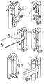
- FIGS. 15 to 19 show further components 27 to 31 which have connecting members 38 to 42 for the guided engagement in a recess 7 of a profile 1 according to FIG. 1, which is located between the profile ends.
- the connecting members 38 to 42 essentially have in common that they fit into the recess 7 almost without play and are formed, for example, by a correspondingly dimensioned rectangular rod piece, which can be secured in the manner of a fastening member, for example by screws, relative to the connecting element 5.
- the embodiment according to FIG. 15 is a connecting piece for transverse and longitudinal profiles 1, only one of which is shown and which can be attached to this connecting piece at any point in its longitudinal direction.
- two identical connecting members are to be ver one to the bottom surfaces 13 of both binding profiles right-angled axis 48 pivotally arranged to each other, this axis 48 lies in the middle of the width of the bottom surfaces 13.
- the profiles 1 connected to one another via the component 27 can be set at an angle to one another pivoting about the axis 48.
- the connecting members 38 protrude only slightly above the flanks of the profile bars 4, so that the two interconnected profiles 1 only have the distance from one another that is required as a play. It is also conceivable to arrange the two connecting members 38 rigidly or fixably to one another at the desired angle, so that the two interconnected profiles 1 assume a precisely defined angle to one another.
- the connecting member 39 of the component 28 according to Figure 16 forms part of a tenon hinge, the hinge axis 49 is parallel to the profile 1 in the central plane 3 and within the associated recess 7, so that there is a concealed hinge, the other hinge part for the attachment of the Component to be pivoted, such as a door or the like protruding from the profile 1.
- the component 29 according to FIG. 17 is, for example, a writing surface for a chair, which is rigidly connected to the connecting element 40, which is designed similarly to the connecting element 38.
- the component 30 is designed as a floor mounting bracket, the bottom of which lies the angled limb projecting outwards beyond the profile with its underside in the plane of the lower end face of the profiled section 1 and the angled formed by the other angled limb closing member 41 is arranged completely in the associated recess 7.
- This component 30 is suitable, for example, as a panic protection for row seating, in which individual chairs are secured against slipping against the floor at greater intervals and the securing can nevertheless be easily released in an emergency.
- the pin passes through the horizontal angle leg and engages in a corresponding counter opening in the floor in such a way that it can only be disengaged by lifting the chair.
- the component 31 according to FIG. 19 is an armrest which is formed by the one, longer leg of the angular component 31, the other leg of which forms the associated connecting member 42.
- the profile 1p according to FIG. 20 has abutment teeth 50 on the side faces of one or both recesses 7p, which run through the entire length of the profile 1p.
- the recess 7p is assigned, for example, a rubber-elastic connecting member 43 which can be inserted into the recess with a prestress such that it is pressed into the abutment teeth 50 in a claw-like manner and is suitable for supporting a further component in the form of, for example, a table top 32.
- FIG. 21 shows an end piece 51, for example for a profile 1, which is not secured by engagement in the recesses 7, but rather engages directly in the connecting element 5 from the associated end face.
- the end piece 51 has a pin 52 protruding at a right angle at an end plate 24qu, for example in the form of a dowel pin, a screw pin or the like, which engages in a corresponding opening in the connecting member 5.
- Figure 22 shows a further component 33 in the form of an end piece, which has an end plate 24r and on both sides protruding over this connection members 44 in the form of plugs that two profiles 1 can be connected to one another in their longitudinal direction and the end plate 24r to each other facing end faces of both profiles covering or as a flat intermediate member.
- the connecting members 44 are adapted to a profile 1 according to FIG. 1 and are provided in alignment with one another on both sides of the end plate 24r, the connecting members 44 being able to be of different or the same length on both sides of the end plate 24r.
- FIG. 23 shows a further component 34, which, like the component 26 according to FIG. 14, is provided for connecting two parallel profiles.
- the connecting members 45 in the form of plugs adapted to the recesses 7 of the profile 1 are arranged in pairs such that the two profiles to be connected in clamp-like manner by the component 34 do not lie directly against one another but are at a predetermined distance from one another.
- the two end plates 24s are kept at a distance from one another via a connecting web 53.
- While the components 26 and 34 according to FIGS. 14 and 23 are designed such that they connect the associated profiles to one another in such a way that they are adjacent to one another in the direction of the central plane 3, the component 35 is designed such that the components connected by it Profiles 1 according to FIG. 24 lie adjacent to one another in the direction of the central plane 2.
- the component 35 engages with plug-like connecting members 46 from the lower ends of the profiles 1 in their recesses 7, the profiles 1 being able to form, for example, the legs or supports of a chair, table or the like and are at a corresponding distance from one another.
- the end plate 24t of the component 35 which extends through both profiles forms, for example, a sliding curve for the associated furniture.
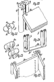
- the further component 36 according to FIG. 25 is, for example, the side walls of a retractable base cabinet, the associated edge zones of which form the connecting members 47, which fit into the cutouts 7 in the profiles 1. Immediately adjacent to the profiles 1, the side walls are connected to one another via a cross plate 54.
- FIG. 26 shows a chair 17 constructed using profiles according to the invention, the four stand supports 55, 56 of which are formed by sections of the profile 1 according to FIG. 1.
- the rear stand supports 55 are higher than the front stand supports 56 and carry a back support 58 above the seat part on a curved transverse frame 59.
- These ends 63 like the ends of the transverse frame 59 which are aligned with one another, are fastened in the two respective stand supports 55, 56 in accordance with the explanations with reference to FIG.
- the upper and lower ends of the stand supports 56 are covered with end pieces, at least one of which is used as a label carrier can be seen that its end plate 24u or the Au is ß enamide its outer plug 64 with a, for example, embossed lettering or numbering provided.
- the chair according to FIG. 27 differs from that according to FIG. 26 essentially only in that it is provided with armrests or armrests 31u, which are fastened with suitable fastening members in the ends of the cross frame 59, braced against the associated outer surfaces of the rear stand supports 55, and possibly suitable with adjacent chairs, such that only a common armrest is provided between adjacent chairs.
- the table 65 according to FIG. 28 has, for example, stand supports 66 which are made from profiles according to FIG. 8, the two outer profile webs 4g merging in the lower region into horizontal sections facing away from one another and carrying a section 67 of the connecting elements 5 projecting over their undersides, which forms the footprint of the table, for example in the form of a plastic glider.
- the table top 68 is provided in the manner of a edging with an edging which has a U-shaped profile bar 69 on the underside of the table top 68, a profile bar 70 which is angular in cross section at the top and which connects a flat strip-shaped connecting element 71 which extends from the upright angle leg of the upper profile bar 70 is overlapped on the outside, so that there is also a groove-shaped recess with a recessed bottom surface.
- the connecting element 5v can also have a star-shaped cross section and carry a profile bar 4v on each strip section 15v, in the exemplary embodiment shown five evenly distributed profile bars 4v.
- the lower ends of the profile bars 4v go in Stand arms 73 projecting radially from the connecting element 5v, each of which carries a roller 74 on the underside in the region of their free ends.
- this arrangement is provided to form a single-column swivel chair foot 72, the column of which stands in the central axis of the connecting element 5v.
- the profile 1w according to the invention can be subdivided in a simple manner into sections 75 lying at an angle to one another, the connecting element 5w being able to be formed in one piece by appropriate cutting or bending, so that even in such an embodiment very high strengths are achieved surrender.
- the sections of the profile bars 4w which adjoin one another at an angle abut at 76 at miter cut and, with their abutting end faces can also be directly connected to one another, for example by gluing.
Landscapes
- Life Sciences & Earth Sciences (AREA)
- Engineering & Computer Science (AREA)
- Wood Science & Technology (AREA)
- Furniture Connections (AREA)
- Connection Of Plates (AREA)
- Mutual Connection Of Rods And Tubes (AREA)
- Joining Of Building Structures In Genera (AREA)
- Assembled Shelves (AREA)
Abstract
Description
- Die Erfindung betrifft ein Verbund-Stangenprofil als Bauelement fUr Einrichtungs-Baukörper, insbesondere Möbel.
- Profile dieser Art haben meist eine wesentlich tragende Funktion und sind gleichzeitig gestalterische Elemente der Baukörper, was unter der Bedingung geringen Materialverbrauches und vielseitiger Einsatzmöglichkeiten meist sehr schwer miteinander zu vereinbaren.
- Der Erfindung liegt die Aufgabe zugrunde ein Verbund-Stangenprofil zu schaffen, welches bei einfacher Ausbildung hinsichtlich seiner Festigkeit und Oberflächengliederung an die unterschiedlichsten Erfordernisse angepaßt und unter hoher Festigkeit mit weiteren Bauteilen verbunden werden kann.
- Diese Aufgabe wird bei einem Verbund-Stangenprofil der eingangs genannten Art gemäß der Erfindung dadurch gelöst, daß das Profil aus wenigstens zwei einander etwa parallel gegenüberliegenden Profilstäben und wenigstens einem an deren einander zugekehrten Profilseiten eingesetzten, gesonderten Verbindungselement besteht, das gegenüber den Profilstäben unter Bildung von längs des Profiles verlaufenden Aussparungen zurückversetzt ist und daß die Aussparungen als Aufnahmeöffnungen für Anschlußglieder von weiteren Bauteilen ausgebildet sind. Dadurch können, je nach den Erfordernissen, unterschiedlichste Materialien für die Profilstäbe und die Verbindungselemente verwendet sowie unter Wahrung einer einheitlichen optischen Erscheinung für ein und denselben Baukörper bzw. für Baukörper einer Gruppe Stangenprofile mit unterschiedlichen Festigkeiten dadurch erzielt werden, daß die Querschnitte der Profilstäbe und/ oder der Verbindungselemente variiert werden.
- Eine besonders hohe Festigkeit bei schlanken Gesamtquerschnitten ist dadurch zu erzielen, daß das Verbindungselement in, vorzugsweise in einer gemeinsamen Mittelebene liegende, Verbundnuten des jeweiligen, insbesondere im Querschnitt U-förmigen, Profilstabes eingesetzt und durch Klebung,Leimung, Verzahnung oder dgl. unlösbar befestigt ist. Dadurch ergibt sich aus; unterschiedlichen Längsprofilen ein besonders kompaktes Stangenprofil, dessen Querschnitt beispielsweise demjenigen eines Flachstabes mit abgerundeten Kanten und zwei mittigen Längsnuten an den Flachseiten entsprechen kann.
- Für weitere Anwendungsgebiete ist es in vorteilhafter Weise möglich, daß der Profilstab zwei oder mehr in einer Mittelebene liegende und/oder im Winkel zueinander versetzte Verbundnuten mit jeweils mindestens einem eingesetzten Verbindungselement oder dgl. aufweist. Die Verbindungselemente können also in Reihe nebeneinander und/oder sternförmig zueinander angeordnet sein.
- Es ist denkbar als Verbindungselement einzelne, unmittelbar aneinander schließende und/oder auf Lücke benachbart zueinander liegende Teile vorzusehen, jedoch läßt sich das Profil bei hoher Festigkeit im wesentlichen endlos herstellen und dann durch Ablängen auf das jeweils gewünschte Maß zuschneiden, wenn mindestens ein Verbindungselement im wesentlichen leistenförmig begrenzt ist und vorzugsweise zwischen den Profilstäben eine Dicke aufweist, die höchstens geringfügig größer als die Breite der, insbesondere rechteckig begrenzten. Verbundnuten ist. Ist diese Dicke des, beispielsweise flachstabförmigen Verbindungselementes gleich der Breite der Verbundnuten, so kann das Verbindungselement im Querschnitt ununterbrochen viereckig begrenzt sein.
- Durch die erfindungsgemäße Ausbildung ist es auch möglich, daß mindestens ein Profilstab und/oder ein Verbindungselement durch ein Hohlprofil, insbesondere ein Hohlkammerprofil gebildet ist, so daß einerseits bei geringem Gewicht hohe Festigkeiten erzielt werden und andererseits Hohlräume für die Aufnahme von Versorgungssträngen, für Beschläge und ähnliches gegeben sind.
- Bei einer bevorzugten Ausführungsform besteht mindestens ein Profilstab und/oder wenigstens ein Teil des Verbindungselementes aus einem Holzwerkstoff, wie Schichtholz, Sperrholz, Massivholz oder dgl., wobei der Faserverlauf der Profilstäbe einerseits und der Verbindungselemente andererseits unterschiedlich gewählt und dadurch an die jeweiligen Erfordernisse angepasst werden kann; ebenso können für die Profilstäbe und das Verbindungselement bzw. die Verbindungselemente unterschiedliche Holzwerkstoffe verwendet werden, beispielsweise für die Profilstäbe Massivholz und für das, wesentliche Tragfunktionen übernehmende Verbindungselement Schichtholz, Sperrholz oder dgl.. Es kann aber auch zweckmäßig sein, wenn mindestens ein Profilstab und/oder wenigstens ein Teil des Verbindungselementes durch ein Strangprofil aus Metall oder dgl. gebildet ist, so daß noch höhere Festigkeiten bei gleichen Querschnitten erzielt werden können.
- Je nach Verwendung ist es auch möglich, das Profil bei ansonsten gleichem äußeren Aussehen so auszugestalten, daß die nutartige Aussparung im Querschnitt hinterschnitten, beipsielsweise T-nutenförmig, schwalbenschwanzförmig oder ähnlich ausgebildet ist und vorzugsweise ihre seitlichen Begrenzungsflächen ausschließlich durch die Profilstäbe und/oder ihre Bodenfläche ausschließlich durch das Verbindungselement gebildet sind. Dadurch können .Schienen bzw. formschlüssig sichernde Profilnuten beispielsweise zur Führung von Schwebetüren, Schiebetüren, Rolladenlamellen, Schubladen oder dgl. geschaffen werden. Sowohl die mit ebenen Innenflächen rechtwinklig bzw. annähernd quadratisch begrenzte wie auch die hinterschnittene Aussparung eignet sich in vorteilhafter Weise für die Aufnahme der verschiedensten weiteren Bauteile, beipsielsweise eines verdeckten Scharnieres, einer Rückwand, einer Seitenwand, eines Regalbodens, einer Regalschiene, von Hinweisschildern, von Reihen- bzw. Platznumerierungen, von Bildtafelplatten, von Reihenverbindungselementen, von Armlehnen, Schreibplatten, Schallschluck-Elementen, von Stromschienen, Kabelkanälen und Steckerschienen, von Einhängeplatten bei Tischen, von Dichtungsprofilen bzw. -8ürsten, von einschiebbaren Unterschränken, von Vorhangschienen, von flächigen Leinwand- oder Sonnenschutzteilen, von Frontblenden und Seitenblenden sowie von vielem mehr. Sowohl die in die Verbundnuten wie auch die in die Aussparungen eingesetzten Teile können dabei aus den unterschiedlichsten Materialien, beispielsweise Glas, Aluminium, Kunststoff und dgl. bestehen und beispielsweise auch Gitterstruktur haben.
- Nach einem weiteren Vorschlag gemäß der Erfindung sind die Seitenflächen der Aussparung mit, insbesondere über ihre Länge gleichmäßig verteilten, Formschlußgliedern, vorzugsweise einer Widerlagerzahnung, also beispielsweise einer sägezahnförmigen Rasterzahnung versehen, so daß zwischen diese Seitenflächen beispielsweise ein gummielastisches Tragelement vorgespannt eingesetzt werden und zum stufenlos höhenverstellbaren Halten von Zwischenböden oder dgl. verwendet werden kann. Statt dessen oder aber auch zusätzlich hierzu ist zweckmäßig die Bodenfläche der Aussparung mit, insbesondere über ihre Länge gleichmäßig verteilten, Formschlußgliedern, vorzugsweise mindestens einer Lochreihe versehen, die wenigstens teilweise unmittelbar im Verbindungselement und/oder in einem in die Aussparung eingesetzten weiteren Schienenstab, beispielsweise einer Regalschiene vorgesehen ist.
- Eine besonders vorteilhafte Weiterbildung des Erfindungsgegenstandes besteht darin, daß das Verbindungselement für die Aufnahme des Endes eines im Winkel anschließenden Bauteiles eine fensterartige, insbesondere nur bis zu den Seitenflächen der Aussparung reichende Stecköffnung aufweist, von der mindestens zwei gegenüberliegende Begrenzungsflächen als Befestigungsflächen, beispielsweise als Spannflächen für den durch Verkeilung verspannten Bauteil, ausgebildet sind, der dann sowohl beiderseits des Verbindungselementes an den einander zugekehrten Profilflächen der Profilstäbe, wie auch an den zugehörigen gegenüberliegenden Begrenzungsflächen der Stecköffnung verspannt ist und trotz verhältnismäßig kleiner Anschlußquerschnitte eine Verbindung von hoher Festigkeit gewährleistet. Bei einer vorteilhaften Ausführungsform bilden beispielsweise Abschnitte des erfindungsgemäßen Profiles die Standstützen eines vierbeinigen Stuhles, von dem eine vordere und eine hintere Zarge mit ihren über einen sie einbeziehenden Zargenrahmen seitlich vorstehenden Enden als weiterer Bauteil an die Aussparungen der zugehörigen Standstützen-Profile anschließen, wobei diese, ebenfalls als Flachstäbe ausgebildeten Zargen zweckmäßig eine Dicke haben, die genau gleich der Breite der Aussparungen der Standstützen, also genau gleich dem Abstand zwischen den Profilstäben der jeweiligen Standstütze ist.
- Durch die beschriebene Ausbildung bilden auch die Enden des erfindungsgemäßen Stangenprofiles Aufnahmestecker für die formschlüssige Anordnung entsprechender Endstücke, welche je nach den Erfordernissen für die unterschiedlichsten technischen Wirkungen ausgebildet sein können. Beispielsweise kann mindestens ein Ende des Profiles mit einem weiteren Bauteil in Form eines Endstückes versehen sein, das zwischen die Profilstäbe formschlüssig eingreifende Stecker und insbesondere eine Endplatte aufweist, welche deckungsgleich zu den Endflächen der Profilstäbe liegt und die Aussparungen endseitig abdeckt, so daß ein glattflächiger Abschluß des, beispielsweise nur durch einen Trennschnitt bearbeiteten Profilendes erzielt wird. Dieser oder ein anders ausgebildeter endseitiger Bauteil kann zum Beispiel wenigstens einen Stecker für den klammerartig endseitig verbindenden Eingriff in die Aussparungen benachbarter Profile aufweisen, so daß zwei parallel aneinander- oder im entsprechenden Abstand zueinander liegende Profil-Abschnitte durch einen oder zwei dieser Bauteile klammerartig zu einem in sich formstabilen Bauelement zusammengefasst werden können. Der mit dem Stecker bzw. den Steckern versehene Bauteil kann dabei so ausgebildet sein, daß er verdrehsicher, auswechselbar, in linear aneinander schließende Profile eingreifend und in vielfältiger anderer Weise angeordnet werden kann. Beispielsweise kann dieser Bauteil mit einer Mikrobuchse, mit einem Leuchtkörper für Notbeleuchtung oder als Leselampe ausgestaltet sein. Des weiteren kann er zum Einhängen einer Schreibplatte, eines Tabletts, einer Schreibstütze, eines Notenständers, eines Krankenstuhles, einer Kniebank, einer Fußstütze, eines Drehexzenters, eines Kartenständers, einer Kleiderstange, einer Taschenablage, einer Zeitschriftenablage, einer Glasplatte und vielem mehr ausgebildet sein.
- Eine besonders vorteilhafte Weiterbildung des Erfindungsgegenstandes besteht darin, daß mindestens ein weiterer Bauteil ein Befestigungsglied für den zwischen den Profilenden liegenden, zentrierten bzw. geführten Eingriff in wenigstens eine Aussparung mindestens eines Profiles aufweist, wobei vorzugsweise zwei Befestigungsglieder im Winkel zueinander liegen und/oder um eine zu den Bodenflächen der Aussparungen der zu verbindenden Profile etwa rechtwinklige Achse schwenkbar aneinander gelagert sind. Dadurch können alle notwendigen Teile bzw. Möbel-Accessoirs, wie Armlehnen, Schreibplatten und dgl. entlang des jeweiligen Profiles an jeder beliebigen bzw. geeigneten Stelle in der Aussparung befestigt werden. Sind zwei im Winkel zueinander liegende Befestigungsglieder vorgesehen, so ist der weitere Bauteil geeignet, zwei Stangenprofile in einem Knotenpunkt miteinander zu verbinden, wobei bei schwenkbarer Lagerung der beiden Befestigungsglieder aneinander die beiden Stangenprofile jede beliebige Winkelstellung zueinander einnehmen können.
- Der weitere Bauteil ist, beispielsweise bei Verwendung für eine Reihenbestuhlung, in vorteilhafter Weise auch als Bezeichnungsträger, beispielsweise für die Sitzplatznummer oder die Stuhlreihe geeignet, wobei zum Beispiel die Endplatte für die Sitznummer und die Außenfläche eines Steckers für die Reihennummer verwendet werden kann.
- Des weiteren kann gemäß der Erfindung mindestens ein weiterer Bauteil als Standfuß, insbesondere als Bodenschraubwinkel, Bodengleiter, Gleitkuve, Laufrolle, höhenverstellbarer Niveauausgleichfuß oder dgl. ausgebildet sein, so daß sich ein schonender Abschluß des unteren Endes des Stangenprofiles ergibt.
- Das erfindungsgemäße Profil eignet sich in vorteilhafter Weise als variables Konstruktionselement, weil das, ein Zwischenstück bildende Verbindungselement, beispielsweise bei gleich bleibenden Profilstäben, in unterschiedlichster Weise dimensioniert werden kann. Die beiden Aussparungen an den beiden Seiten des Profiles eignen sich zur Lösung vieler, im Möbel- und Innenausbau auftretender technischer Probleme, beispielsweise zur Zentrierung, als Anschlag für einen zweiten Teil, zur abgesetzten Farbgebung usw. Das Verbindungselement kann beispielsweise gesondert von den Profilstäben lackiert werden, wonach erst die Profilstäbe und das Verbindungselement zum Verbundprofil zusammengesetzt werden, so daß sich auch dann eine einfache Fertigung ergibt, wenn die Bodenfläche der Aussparung eine andere Farbgebung als die Ubrigen Oberflächen des Profiles aufweist. Das Verbindungselement kann auch in Sandwichbauweise aus Schichten unterschiedlicher Werkstoffe zusammen gesetzt oder durch zwei im Abstand voneinander liegende, beispielsweise leistenförmige Einzelelemente gebildet sein, die in jedem Profilstab in gesonderte Verbundnuten eingesetzt sind und zwischen sich ein Hohlraum begrenzen, in den beispielsweise ein Kabelstrang für elektrische Stromanschlüsse integriert ist. Das Profil eignet sich aufgrund der beschriebenen Vorteile besonders zur Herstellung von Tischen, Klapptischen, Stühlen, Sesseln, Sesselgruppen, Schränken, Vitrinen, Regalen, Schreibtischen, Schreibmaschinentischen, Rednerpulten, Betten, Liegen, Hörsaalgestühl, Containern, Hinweisschildern und vielem mehr sowie im Laden- und Messebau.
- Merkmale von bevorzugten Weiterbildungen der Erfindung gehen auch aus der Beschreibung und den Zeichnungen hervor, wobei diese Merkmale und die der Unteransprüche jeweils für sich allein oder zu mehreren in Form von Unterkombinationen bei einer Ausführungsform der Erfindung verwirklicht sein können.
- Mehrere AusfUhrungsbeispiele der Erfindung sind in den Zeichnungen dargestellt und werden im folgenden näher erläutert. Es zeigen:
- Fig. 1 ein erfindungsgemäßes Verbund-Stangenprofil in Endansicht,
- Fig. 2 bis 8 weitere Ausführungsbeispiele von Profilen in Darstellungen entsprechend Figur 1,
- Fig. 9 den Anschluß eines im Winkel liegenden Bauteiles im Querschnitt durch das Profil, Fig. 10 bis 13 weitere Ausführungsformen von Profilen in perspektivischen Darstellungen,
- Fig. 14 zwei mit einem klammerartigen Bauteil zusammenzufassende Profile in perspektivischer Darstellung,
- Fig. 15 bis 20 Ausführungsbeispiele von weiteren Bauteilen zum Einsetzen zwischen den Profilenden,
- Fig. 21 bis 24 Ausführungsbeispiele für endseitig an den Profilen anzubringende Bauteile,
- Fig. 25 ein Möbelkörper unter Verwendung erfindungsgemäßer Profile,
- Fig. 26 ein unter Verwendung erfindungsgemäßer Profile aufgebauter Stuhl in perspektivischer Darstellung,
- Fig. 27 eine Abwandlung des Stuhles gemäß Figur 26,
- Fig. 28 ein unter Verwendung erfindungsgemäßer Profile aufgebauter Tisch,
- Fig. 29 einen Einsäulen-Fuß, beispielsweise für einen Drehstuhl im Schnitt nach der Linie XXIX-XXIX in Figur 30
- Fig. 30 der Fuß gemäß Figur 29 in Ansicht,
- Fig. 31 ein Ausschnitt eines weiteren Verbund-Stangenprofiles in Ansicht.
- Wie Figur 1 zeigt weist ein erfindungsgemäßes Verbund-Stangenprofil über seine Länge durchgehend gleiche, annähernd H-förmige Querschnitte auf, wobei seine Querschnittserstreckung parallel zu der durch den H-Quersteg gehenden Mittelebene 2 in aller Regel mindestens doppelt so groß wie parallel zu der rechtwinklig dazu stehenden Mittelebene 3 ist. An den quer zur Mittelebene 3 liegenden Längsflächen ist das Profil teilkreisförmig, im dargestellten Ausführungsbeispiel halbkreisförmig abgerundet, während die Übrigen Kanten, insbesondere die Begrenzungskanten von zwei nutartigen Aussparungen scharfkantig sind. Das Profil ist sowohl symmetrisch zur Mittelebene 2 wie auch symmetrisch zur Mittelebene 3, also bevorzugt achssymmetrisch zu einer Längsachse ausgebildet, die in beiden Mittelebenen liegt.
- Das Profil 1 besteht im wesentlichen aus drei gesonderten Teilen, die durch geeignete Mittel, wie beispielsweise Leimung nach ihrer Fertigbearbeitung, das heißt gegebenenfalls auch nach ihrer Lackierung unlösbar verbunden sind. Zwei dieser Teile sind gleich ausgebildet und bilden zwei einander beiderseits der Mittelebene 3 gegenüberliegende Profilstäbe 4, deren Querschnittserstreckung parallel zur Mittelebene 2 etwa gleich bzw. geringfügig kleiner als ihre Querschnittserstreckung parallel zur Mittelebene 3 ist. Diese Profilstäbe 4 bilden die teilkreisförmig abgerundeten Längskantenflächen 6 des Profiles. Symmetrisch zur Mittelebene 2 liegend ist zwischen die Profilstäbe 4 ein Verbindungselement 5 in Form eines im Querschnitt länglich rechteckigen Flachstabes eingesetzt. Dieses Verbindungselement 5, das zweckmäßig ununterbrochen über die Länge der Profilstäbe 4 durchgeht bildet ein Distanzglied zwischen den Profilstäben 4, derart daß zwischen diesen die beiden beiderseits des Verbindungselementes 5 liegenden, im Querschnitt gleichen nutförmigen Aussparungen 7 über die ganze Länge des Profiles ununterbrochen durchgehen.
- Die Breite dieser nach Art von Rechtecknuten begrenzten Aussparungen 7 ist, zweckmäßig etwa um die Hälfte, größer als ihre Tiefe, die wiederum größer als die Dicke des Verbindungselementes 5 im Bereich der Aussparungen 7 ist. Zur Aufnahme des Verbindungselementes 5 weist jeder Profilstab an seiner dem anderen Profilstab 4 zugekehrten, ebenen und zur Mittelebene 3 parallelen Innenfläche 9 eine symmetrisch zur Mittelebene 2 liegende Verbundnut 8 auf, die vom eingreifenden Abschnitt des Verbindungselementes 5 vollständig ausgefüllt und im dargestellten Ausführungsbeispiel nach Art einer Rechtecknut begrenzt ist, deren Tiefe größer als ihre Breite ist. Das Verbindungselement 5 greift somit in jeden Profilstab 4 auf einer Tiefe ein, die etwa der Hälfte von dessen Querschnittserstreckung parallel zur Mittelebene 2 entspricht und etwa um ein Drittel kleiner als die Breite der Aussparungen 7 ist. Die Seitenflächen der Verbundnuten 8 liegen parallel zur Mittelebene 2, während ihre Bodenflächen rechtwinklig dazu liegen. Die Obergangs-Längskanten 10 zwischen den Innenflächen 9 bzw. den Seitenflächen der Aussparungen 7 und den äußeren Flankenflächen 12 der Profilstäbe 4 sind im Querschnitt rechtwinklig scharfkantig ebenso wie die inneren einspringenden Eckkanten der Aussparungen 7, die durch den Obergang zwischen den Innenflächen 9 und den frei liegenden Flankenflächen des Verbindungselementes 5 gebildet sind, welche die Bodenflächen 13 der Aussparungen 7 bilden.
- Die Innenflächen 9 der Profilstäbe 4 bilden die Seitenflächen 14 der Aussparungen 7. Im Anschluß an die Längskanten 10 sind die Flankenflächen 12 eben, wonach sie in die abgerundet Längskantenflächen 6 übergehen. Die Mittelachse der Längskantenflächen 6 liegt somit etwa . in der Bodenfläche der zugehörigen Verbundnut 8. Die
Seitenabschnitte 15 des Verbindungselementes 5, welche in die Verbundnuten 8 eingreifen,haben beim Ausführungsbeispiel nach Figur 1 dieselbe Dicke wie das übrige Verbindungselement 5, also wie dessen zwischen den Profilstäben 4 liegender Abschnitt, derart, daß die zugehörigen - Außenflächen des Verbindungselementes 5 über seine Breite ununterbrochen und gegebenenfalls eben durchgehen. - In den Figuren 2 bis 14 sind für einander entsprechende Teile die gleichen Bezugszeichen wie in Figur 1, jedoch mit unterschiedlichen Buchstabenindices verwendet.
- Das Profil 1a gemäß Figur 2 weist im wesentlichen gleiche Profilstäbe 4a wie das Profil gemäß Figur 1 auf, jedoch ist der zwischen diesen Profilstäben 4a liegende Abschnitt des Verbindungselementes 5a dicker als beim Ausführungsbeispiel nach Figur 1. Die in die Verbundnuten eingreifenden Leistenabschnitte 15a des Verbindungselementes 5a weisen jedoch gleiche Dicke wie beim Ausführungsbeispiel nach Figur 1 auf, sind also in der Dicke gegenüber dem Mittelabschnitt geringfügig reduziert. Außerdem sind ihre den Seitenflächen der Verbundnuten 8a zugehörigen Außenflächen mit einer beispielsweise widerhaken- bzw. sägezahnförmigen Längszahnung 16 versehen, derart daß sie krallenartig in die Seitenflächen der Verbundnuten 8a unter Vorspannung eingreifen und sich dadurch eine sehr stabile Verbindung ergibt.
- Die Profilstäbe 4b des Profiles 1b gemäß Figur 3 sind im Querschnitt rechteckig bzw. annähernd quadratisch, wobei alle Längskanten der Profilstäbe annähernd viertelkreisförmig abgerundet sind, derart daß die den Aussparungen 7b zugehörigen Längskanten 10b ebenfalls abgerundet sind. Die voneinander abgekehrten Längskantenflächen 6b der Profilstäbe 4b sind durch ebene Flächen gebildet, welche parallel zur Mittelebene 3b liegen.
- Wie Figur 4 zeigt, können die Profilstäbe 4c im Querschnitt auch so ausgebildet sein, daß die Aussparungen 7c zu ihren offenen Seiten in der Breite annähernd spitzwinklig erweitert sind, da die Innenflächen 9c auf jeder Seite des Verbindungselementes 5c zu diesem hin konvergieren. Die Innenflächen 9c gehen über abgerundete Abschnitte in Außenflächen 12c, 6c der Profilstäbe :4c über, welche zu deren voneinander abgekehrten Seiten abgerundet dreieckförmig konvergieren.
- Demgegenüber weisen die im Querschnitt spitzwinklig gleichschenkligen bzw. gleichseitigen Profilstäbe 4d ebene Außenflächen auf, die durch die Innenflächen 9d und die Flankenflächen 12d gebildet sind, wobei diese Außenflächen über abgerundete Längskanten 6d,10d ineinander übergehen.
- Die Profilstäbe 4e können auch gemäß Figur 6 durch Hohlprofile gebildet sein, welche zweckmäßig über ihren Querschnitt konstante Wanddicke und eine durchgehend geschlossene Wandung aufweisen.
- Wie Figur 7 zeigt kann das Verbindungselement 5f auch aus mehreren Teilen zusammengesetzt sein, deren Teilungsebenen zweckmäßig etwa parallel zur Mittelebene 2f liegen. Diese Teile können durch die Schichten von Schichtholz oder Sperrholz, durch Laminate im Sandwichaufbau oder dgl. gebildet sein. Des weiteren ist es denkbar, daß zwischen mindestens zwei Teilen des Verbindungselementes 5f Lücken frei gelassen werden, welche über die Länge des Verbindungselementes 5f durchgehen und somit über dessen Breite und Länge durchgehende Hohlräume bilden.
- In Figur 8 ist ein Profil 1g dargestellt, das drei Profilstäbe 4g,4'g und zwei Verbindungselemente 5g aufweist, die im Querschnitt alle parallel zur Mittelebene 2g hintereinander liegen. Die beiden äußeren Profilstäbe 4g entsprechen den beschriebenen Profilstäben und weisen an ihren Innenflächen 9g jeweils eine Verbundnut 8g auf, während der Profilstab 4'g eine von den Profilstäben 4g abweichende Querschnittsform, im dargestellten Ausführungsbeispiel rechteckigen Querschnitt aufweist und an seinen voneinander abgekehrten, den Innenflächen 9g zugekehrten Längsflächen 9'g jeweils mit einer Verbundnut 8'g versehen ist. Die Verbundnuten 8'g haben eine gegenüber den Verbundnuten 8g geringere Tiefe, wobei jedoch die Querschnittserstreckung des Profilstabes 4'g parallel zur Mittelebene 2g annähernd gleich derjenigen der Profilstäbe 4g ist. Durch diese Ausbildung weist das Profil 1g an jeder Seite zwei nebeneinander liegende, im Querschnitt gleiche Aussparungen 7g auf.
- In Figur 9 ist die Befestigung eines weiteren Bauteiles 25 an einem erfindungsgemäßen Profil, im dargestellten Ausführungsbeispiel am Profil 1 gemäß Figur 1 dargestellt; bei dem weiteren Bauteil 25 handelt es sich beispielsweise um eine im Querschnitt flach rechteckige Zarge aus Holz oder dgl., deren Dicke genau gleich der Breite der Aussparungen 7 ist. Zum Einsetzen des Bauteils 25 ist in das Verbindungselement 5 eine Stecköffnung 18 eingebracht, deren Erstreckung in Längsrichtung des Profiles 1 gleich der Querschnittshöhe des Bauteiles 25 ist und deren seitliche Begrenzungsflächen 19 in der Ebene der jeweils zugehörigen, zueinander ebenengleich liegenden Seitenflächen 14 der Aussparungen 7 liegen, so daß sich über die Dicke des Profiles 1 bzw. zwischen den Flankenflächen 12 ununterbrochen durchgehende seitliche Befestigungsflächen ergeben. Der Bauteil 25 wird von einer Seite des Profiles 1 so weit eingesteckt, bis seine Endfläche 20 bündig mit den zugehörigen Flankenflächen 12 des Profiles 1 abschließt. Dann wird in eine entsprechende Keilschlitzung des Bauteiles 25 von der Endfläche 20 her ein flach spitzwinkliger Keil 21 eingetrieben, der zweckmäßig wenigstens annähernd über die Dicke des Profiles 1 reicht und in der Mittelebene 3 liegt. Durch den Keil 21 wird der Bauteil 25 gegenUber den Seitenflächen 14 beider Aussparungen 7 sowie gegenüber den Begrenzungsflächen 19 der Stecköffnung 18 und somit gegenüber dem Verbindungselement 5, das heißt ununterbrochen Uber die ganze Dicke des Profiles 1 gleichmäßig verspannt.
- Das Profil 1h gemäß Figur 10 weist als Verbindungselement 5h ein Hohlkammerprofil in Form beispielsweise eines Strang-Profiles auf, das über die Breite des Verbindungselementes 5h in mehrere, nach außen außer an den Enden vollständig geschlossene, rechteckig begrenzte Kammern durch Zwischenwände unterteilt ist. Die zwischen den Enden des Verbindungselementes 5h gegeneinander vollständig geschlossenen Kammern können für die Aufnahme von Versorgungssträngen, beispielsweise elektrischen Leitungen oder dgl. verwendet werden.
- Das Profil 1i gemäß Figur 11 weist an den Bodenflächen 13i beider Aussparungen 7i über seine Länge gleichmäßig verteilte Formschlußglieder in Form einer Lochreihe 22 auf, welche in der Mitte der Breite der Aussparungen 7i liegt und durch Löcher gebildet ist, welche das Verbindungselement 5i durchsetzen. Dadurch können beispielsweise in die Lochreihe 22 Träger für Regalböden oder dgl. höhenveränderbar eingesetzt werden. Beim Profil 1k nach Figur 12 sind diese Formschlußglieder nicht unmittelbar im Verbindungsglied 5k vorgesehen, sondern durch einen gesonderten Schienenstab 23 gebildet, welcher in die zugehörige Aussparung 7k eingesetzt ist. Der Schienenstab 23 weist nach Art einer sogenannten Regalschiene übereinander in Reihe liegende länglich rechteckige öffnungen zum wahlweisen Einhängen von Stützwinkeln auf, auf welche Regalborde gelegt werden können. Der Quersteg des im Querschnitt U-förmigen Schienenstabes 23 liegt, damit die Stützwinkel mit ihren hakenartigen Einhängegliedern hinter dem Schienenstab 23 Platz haben, im Abstand vom Verbindungselement 5k, während die Profilschenkel des Schienenstabes 23 an den Seitenflächen der Aussparung 7k ganzflächig anliegen und bis zum Verbindungselement 5k reichen.
- Beim Profil 1m gemäß Figur 13 ist als zusätzlicher Schienenstab 23m eine dreiläufige Vorhangschiene vorgesehen, welche die zugehörige Aussparung 7m im wesentlichen vollständig ausfüllt. Entsprechend der Breite des Schienenstabes 23m liegen die Profilstäbe 4m bei dieser Ausführungsform weiter auseinander als bei den meisten zuvor beschriebenen Profilen, wobei der frei liegende Mittelabschnitt des Verbindungselementes 5m entsprechend breiter ist.
- Figur 14 zeigt parallel mit ihren Flachseiten aneinander liegend zwei gleiche Profile 1n, deren Aussparungen 7n nach Art von Schwalbenschwanznuten hinterschnitten sind. Zur Erzeugung dieser Aussparungsform sind die einander zugekehrten Begrenzungsflächen 9n der Profilstäbe 4n symmetrisch zur Mittelebene 2n stumpfwinklig V-förmig vorgesehen. Dadurch können weitere Bauteile, Befestigungselemente und dgl., die Führungsglieder mit, den Aussparungen 7n entsprechenden Querschnitten aufweisen, in Längsrichtung der Profile 1n in die Aussparungen 7n eingesetzt werden, wonach sie in allen anderen Richtungen formschlüssig gehalten sind. In Figur 14 ist außerdem ein weiteres Ausführungsbeispiel für einen weiteren Bauteil 26 dargestellt, der für die endseitige Anordnung an zwei gemäß Figur 14 aneinander gelegte Profile 1n derart gedacht ist, daß durch diesen Bauteil die beiden Profile 1n klammerart.ig aneinander befestigt werden. Zu diesem Zweck weist der weitere Bauteil 26 als Anschluß-
- glieder 37 an einer Endplatte 24 parallele Stecker auf deren Querschnittsform an die der Aussparungen 7n angepasst ist. Zwei äußere Stecker 37 sind so im Abstand voneinander angeordnet, daß sie bei aneinander gelegten Profilen 1n im wesentlichen spielfrei in die voneinander abgekehrten Aussparungen 7n passen, während ein mittlerer Stecker doppelt schwalbenschwanzförmig so ausgebildet ist, daß er die beiden einander zugekehrten, mit ihren offenen Seiten ineinander übergehenden Aussparungen 7n beider Profile 1n über seine Länge im wesentlichen vollständig spielfrei ausfüllt. Dadurch ergibt sich eine mehrfache formschlüssige Verbindung des Bauteiles 26 mit beiden Profilen 1n, so daß diese mit verhältnismäßig großer Festigkeit sicher aneinander befestigt sind. Die Endplatte 24 ist so ausgebildet und angeordnet, daß sie bei eingestecktem Bauteil 26 beide Endflächen der Profile 1n deckungsgleich abdeckt und die Aussparungen 7n an ihren Enden verschließt.
- In den Figuren 15 bis 19 sind weitere Bauteile 27 bis 31 dargestellt, welche Anschlußglieder 38 bis 42 für den zwischen den Profilenden liegenden, geführten Eingriff in eine Aussparung 7 eines Profiles 1 nach Figur 1 aufweisen. Die Anschlußglieder 38 bis 42 haben im wesentlichen gemeinsam, daß sie nahezu spielfrei in die Aussparung.7 passen und beispielsweise durch ein entsprechend dimensioniertes Rechteckstab-Stück gebildet sind, das nach Art eines Befestigungsgliedes beispielsweise durch Schrauben gegenüber dem Verbindungselement 5 gesichert werden kann. Bei der Ausführungsform nach Figur 15 handelt es sich um ein Verbindungsstück für quer- und längs liegende Profile 1, von denen nur eines dargestellt ist und die gegenüber diesem Verbindungsstück jeweils an beliebiger Stelle in ihrer Längsrichtung befestigt werden können. Zu diesem Zweck sind zwei gleiche Anschlußglieder um eine zu den Bodenflächen 13 beider miteinander zu verbindenden Profile rechtwinklige Achse 48 schwenkbar aneinander angeordnet, wobei diese Achse 48 in der Mitte der Breite der Bodenflächen 13 liegt. Dadurch können die über den Bauteil 27 miteinander verbundenen Profile 1 um die Achse 48 schwenkend gegeneinander im Winkel eingestellt werden. Die Anschlußglieder 38 stehen nur geringfügig über die Flanken der Profilstäbe 4 vor, derart daß die beiden miteinander verbundenen Profile 1 lediglich den als Bewegungsspiel erforderlichen Abstand voneinander haben. Es ist auch denkbar, die beiden Anschlußglieder 38 im gewünschten Winkel starr bzw. festsetzbar aneinander anzuordnen, so daß die beiden miteinander verbundenen Profile 1 einen genau definierten Winkel zueinander einnehmen.
- Das Anschlußglied 39 des Bauteiles 28 gemäß Figur 16 bildet einen Teil eines Zapfenscharmeres, dessen Scharnierachse 49 parallel zum Profil 1 in der Mittelebene 3 sowie innerhalb der zugehörigen Aussparung 7 liegt, so daß sich ein verdeckt angeordnetes Scharnier ergibt, dessen anderer Scharnierteil für die Befestigung des schwenkbar zu lagernden Bauelementes, wie einer Türe oder dgl. aus dem Profil 1 vorsteht.
- Der Bauteil 29 gemäß Figur 17 ist beispielsweise eine Schreibplatte für einen Stuhl, die formstarr mit dem Anschlußglied 40 verbunden ist, welches ähnlich wie das Anschlußglied 38 ausgebildet ist.
- Der Bauteil 30 ist als Bodenbefestigungswinkel ausgebildet, dessen über das Profil nach außen vorstehender unten liegender Winkelschenkel mit seiner Unterseite in der Ebene der unteren Endfläche des Profiles 1 liegt und dessen durch den anderen Winkelschenkel gebildetes Anschlußglied 41 vollständig in der zugehörigen Aussparung 7 angeordnet ist. Dieser Bauteil 30 ist zum Beispiel als Paniksicherung für Reihenbestuhlungen geeignet, bei welchen in größeren Abständen einzelne Stühle mit Stiften gegenüber dem Boden gegen Verrutschen gesichert werden und trotzdem im Notfall die Sicherung leicht gelöst werden kann. Der Stift durchsetzt den horizontalen Winkelschenkel und greift in eine entsprechende Gegenöffnung im Fußboden derart ein, daß er lediglich durch Anheben des Stuhles außer Eingriff gebracht werden kann.
- Der Bauteil 31 gemäß Figur 19 ist eine Armlehne, welche durch den einen, längeren Schenkel des winkelförmigen Bauteiles 31 gebildet ist, dessen anderer Schenkel das zugehörige Anschlußglied 42 bildet.
- Das Profil 1p nach Figur 20 weist an den Seitenflächen einer oder beider Aussparungen 7p Widerlagerzahnungen 50 auf, die über die ganze Länge des Profiles 1p durchgehen. Der Aussparung 7p ist ein beispielsweise gummielastisches Anschlußglied 43 zugeordnet, welches mit Vorspannung derart in die Aussparung eingesetzt werden kann, daß es krallenartig sicher haltend in die Widerlagerzahnungen 50 eingedrückt wird und zur Auflage eines weiteren Bauteiles in Form beispielsweise einer Tischplatte 32 geeignet ist.
- In Figur 21 ist ein Endstück 51 beispielsweise für ein Profil 1 dargestellt, welches nicht durch Eingriff in die Aussparungen 7 gesichert ist, sondern von der zugehörigen Endfläche her unmittelbar in das Verbindungselement 5 eingreift. Zu diesem Zweck weist das Endstück 51 an einer Endp'!atte 24qu einen rechtwinklig vorstehenden Zapfen 52 in Form beispielsweise eines Dübelzapfens, eines Schraubzapfens oder dgl. auf, der in eine entsprechende öffnung im Verbindungsglied 5 eingreift.
- Figur 22 zeigt einen weiteren Bauteil 33 in Form eines Endstückes, welches eine Endplatte 24r und beiderseits derart über diese vorstehende Anschlußglieder 44 in Form von Steckern aufweist, daß zwei Profile 1 in ihrer Längsrichtung aneinander gereiht miteinander verbunden werden können und die Endplatte 24r an den einander zugekehrten Endflächen beider Profile abdeckend bzw. als flächiges Zwischenglied anliegt. Die Anschlußglieder 44 sind im dargestellten Ausführungsbeispiel an ein Profil 1 gemäß Figur 1 angepasst und auf beiden Seiten der Endplatte 24r miteinander fluchtend vorgesehen, wobei die Anschlußglieder 44 auf beiden Seiten der Endplatte 24r unterschiedlich oder gleich lang sein können.
- Figur 23 zeigt einen weiteren Bauteil 34, der ähnlich wie der Bauteil 26 gemäß Figur 14 zur Verbindung zweier parallel nebeneinander stehender Profile vorgesehen ist. Die Anschlußglieder 45 in Form von an die Aussparungen 7 des Profiles 1 angepassten Steckern sind jedoch paarweise derart im Abstand voneinander angeordnet, daß die beiden miteinander durch den Bauteil 34 klammerartig zu verbindenden Profile nicht unmittelbar aneinander anliegen sondern mit vorbestimmtem Abstand zueinander stehen. Zu diesem Zweck sind die beiden Endplatten 24s über einen Verbindungssteg 53 im Abstand voneinander gehalten.
- Während die Bauteile 26 und 34 gemäß den Figuren 14 und 23 so ausgebildet sind, daß sie die zugehörigen Profile derart miteinander verbinden, daß diese in Richtung der Mittelebene 3 benachbart zueinander liegen ist der Bauteil 35 so ausgebildet, daß die durch ihn verbundenen Profile 1 gemäß Figur 24 in Richtung der Mittelebene 2 benachbart zueinander liegen. Der Bauteil 35 greift mit steckerartigen Anschlußgliedern 46 von den unteren Enden der Profile 1 in deren Aussparungen 7 ein, wobei die Profile 1 beispielsweise die Standbeine bzw. Standstützen eines Stuhles, Tisches oder dgl. bilden können und in entsprechendem Abstand voneinander stehen. Die über beide Profile durchgehende Endplatte 24t des Bauteils 35 bildet beispielsweise eine Gleitkuve für das zugehörige Möbel.
- Beim weiteren Bauteil 36 gemäß Figur 25 handelt es sich zum Beispiel um die Seitenwände eines einschiebbaren Unterschrankes, deren zugehörige Randzonen die Anschlußglieder 47 bilden, welche in die Aussparungen 7 der Profile 1 passen. Unmittelbar benachbart zu den Profilen 1 sind die Seitenwände über eine Querplatte 54 miteinander verbunden.
- In Figur 26 ist ein unter Verwendung erfindungsgemäßer Profile aufgebauter Stuhl 17 dargestellt, dessen vier Standstützen 55,56 durch Abschnitte des Profiles 1 gemäß Figur 1 gebildet sind. Die hinteren Standstützen 55 sind höher als die vorderen Standstützen 56 und tragen oberhalb des Sitzteiles an einer gekrümmten Querzarge 59 eine Rückenstütze 58. Unterhalb des Sitzteiles 57 befindet sich ein rechteckiger Zargenrahmen 60 aus vier Zargenschenkeln, dessen hintere und vordere Zarge 61,62 mit ihren Enden seitlich über die beiden anderen Zargen vorstehen. Diese Enden 63 sind ebenso wie die miteinander fluchtenden Enden der Querzarge 59 in den beiden jeweils zugehörigen Standstützen 55,56 entsprechend den Erläuterungen anhand Figur 9 befestigt, das heißt also durch Ausschnitte des Verbindungselementes hindurchgeführt und unter Verleimung verkeilt. Die oberen und unteren Enden der Standstützen 56 sind mit Endstücken abgedeckt, von denen mindestens eines als Bezeichnungsträger derart vorgesehen sein kann, daß seine Endplatte 24u oder die Au- ßenfläche seines äußeren Steckers 64 mit einer beispielsweise eingeprägten Beschriftung bzw. Numerierung versehen ist.
- Der Stuhl gemäß Figur 27 unterscheidet sich von demjenigen nach Figur 26 im wesentlichen nur dadurch, daß er mit Armstützen bzw. Armlehnen 31u versehen ist, die mit geeigneten Befestigungsgliedern in den Enden der Querzarge 59 befestigt, gegen die zugehörigen Außenflächen der hinteren Standstützen 55 verspannt, und gegebenenfalls mit benachbarten Stühlen geeignet sind, derart, daß zwischen benachbarten Stühlen nur eine gemeinsame Armlehne vorgesehen ist.
- Der Tisch 65 gemäß Figur 28 weist beispielsweise Standstützen 66 auf, die aus Profilen gemäß Figur 8 hergestellt sind, wobei die beiden äußeren Profilstege 4g im unteren Bereich in voneinander weggerichtete horizontale Abschnitte übergehen und einen über ihre Unterseiten vorstehenden Abschnitt 67 der Verbindungselemente 5 tragen, welcher die Standfläche des Tisches, beispielsweise in Form eines Kunststoffgleiters bildet. Die Tischplatte 68 ist nach Art eines Umleimers mit einer Randeinfassung versehen, welche an der Unterseite der Tischplatte 68 einen U-förmigen Profilstab 69, an der Oberseite einen im Querschnitt winkelförmigen Profilstab 70 und diese verbindend ein flach leistenförmiges Verbindungsetement 71 aufweist, das vom aufrechten Winkelschenkel des oberen Profilstabes 70 an der Außenseite übergriffen wird, so daß sich ebenfalls eine nutförmige Aussparung mit zurückversetzter Bodenfläche ergibt.
- Wie Figur 29 zeigt, kann das Verbindungselement 5v im Querschnitt auch sternförmig ausgebildet sein und an jedem Leistenabschnitt 15v einen Profilstab 4v, im dargestellten Ausführungsbeispiel fünf gleichmäßig verteilte Profilstäbe 4v tragen. Die unteren Enden der Profilstäbe 4v gehen in radial vom Verbindungselement 5v abstehende Standarme 73 über, die jeweils im Bereich ihrer freien Enden an der Unterseite eine Laufrolle 74 tragen. Gemäß Figur 30 ist diese Anordnung zur Bildung eines einsäuligen Drehstuhlfußes 72 vorgesehen, dessen Säule in der Mittelachse des Verbindungselementes 5v steht.
- Wie Figur 31 zeigt, kann das erfindungsgemäße Profil 1w in einfacher Weise in im Winkel zueinander liegende Abschnitte 75 unterteilt sein, wobei das Verbindungselement 5w durch entsprechenden Zuschnitt oder durch Biegung durchgehen einstückig ausgebildet sein kann, so daß sich auch bei einer solchen Ausführungsform sehr hohe Festigkeiten ergeben. Die im Winkel aneinander schließenden Abschnitte der Profilstäbe 4w stoßen demgegenüber bei 76 auf Gehrung geschnitten aneinander an und können mit ihren aneinander stoßenden Endflächen auch unmittelbar miteinander, beispielsweise durch Leimung fest verbunden sein.
Claims (11)
Applications Claiming Priority (2)
| Application Number | Priority Date | Filing Date | Title |
|---|---|---|---|
| DE19843436492 DE3436492A1 (de) | 1984-10-05 | 1984-10-05 | Verbund-stangenprofil |
| DE3436492 | 1984-10-05 |
Publications (2)
| Publication Number | Publication Date |
|---|---|
| EP0176793A2 true EP0176793A2 (de) | 1986-04-09 |
| EP0176793A3 EP0176793A3 (de) | 1986-09-10 |
Family
ID=6247135
Family Applications (1)
| Application Number | Title | Priority Date | Filing Date |
|---|---|---|---|
| EP85111142A Withdrawn EP0176793A3 (de) | 1984-10-05 | 1985-09-04 | Verbund-Stangenprofil |
Country Status (3)
| Country | Link |
|---|---|
| US (1) | US4676469A (de) |
| EP (1) | EP0176793A3 (de) |
| DE (1) | DE3436492A1 (de) |
Cited By (1)
| Publication number | Priority date | Publication date | Assignee | Title |
|---|---|---|---|---|
| US5766601A (en) * | 1990-08-08 | 1998-06-16 | University Of Massachusetts Medical Center | Cross-reactive influenza a immunization |
Families Citing this family (9)
| Publication number | Priority date | Publication date | Assignee | Title |
|---|---|---|---|---|
| US6412249B1 (en) | 1995-10-17 | 2002-07-02 | Boyer Building Products, Inc. | Wall stud |
| US6505449B1 (en) * | 2000-07-27 | 2003-01-14 | Composit Wood Specialties Ltd. | Structural element |
| US20030154660A1 (en) * | 2001-10-19 | 2003-08-21 | Michael Berkowicz | Connector for arranging modular seats in a non-linear array |
| US7017320B2 (en) * | 2002-10-02 | 2006-03-28 | Yuan-Kuan Chen | Metal tubes for guardrail |
| US6796101B2 (en) * | 2002-10-02 | 2004-09-28 | Yuan-Kuan Chen | Metal tubes for guardrail |
| US7523592B2 (en) * | 2005-05-20 | 2009-04-28 | Duracase Proprietary, Llc | Handrail assembly with panel and engaging sleeves |
| NZ602879A (en) * | 2010-03-10 | 2015-06-26 | Solid Racks Pty Ltd | A rack system and bracket |
| WO2015190915A1 (en) * | 2014-06-12 | 2015-12-17 | Alliance Contract Manufacturing Sdn Bhd | Support assembly |
| US9655443B2 (en) * | 2014-07-16 | 2017-05-23 | American Glasscrafters, Inc. | Adjustable shelf support system for medicine cabinets |
Family Cites Families (22)
| Publication number | Priority date | Publication date | Assignee | Title |
|---|---|---|---|---|
| DE7120338U (de) * | 1971-09-02 | Mittermaier E | Aluminium Strangpressprofil zur Her stellung von T , Doppel T oder Kasten profilen zur Verwendung im Fahrzeug und Konstruktionsbau | |
| US919526A (en) * | 1908-07-03 | 1909-04-27 | Ralph Roy Belcher | Shelving construction. |
| US2336604A (en) * | 1940-11-05 | 1943-12-14 | Edward Walter Gordon | Detachable cantilever bracket structure |
| US3261585A (en) * | 1960-04-20 | 1966-07-19 | Victory Metal Mfg Company | Pilaster adapter |
| FI36324A (fi) * | 1964-08-11 | 1966-10-10 | Kooperativa Foerbundet | Stolpe för hyllkonstruktioner |
| US3335992A (en) * | 1965-11-23 | 1967-08-15 | Frazier Donald | Clamping brackets for a rack structure |
| DE1298253B (de) * | 1966-03-21 | 1969-06-26 | Sachau Helmuth Heinrich | Fachbodentraeger mit Klemmvorrichtung zur Hoehenverstellung an einem Hohlprofilpfosten |
| DE6948521U (de) * | 1969-12-16 | 1970-06-04 | Dieckmann Gmbh & Co Kg Erich | Aus mehreren profilen zusamengesetzte regalschiene. |
| CH507687A (de) * | 1970-05-15 | 1971-05-31 | Suter Adolf | Bauteilsatz zur Herstellung eines Anbaumöbels |
| FR2094260A5 (de) * | 1970-06-15 | 1972-02-04 | Vincens Rene | |
| US3735548A (en) * | 1970-09-10 | 1973-05-29 | A Ferrari | Prefabricated self-supporting reinforced concrete shelving element for forming storage spaces |
| US3712015A (en) * | 1970-10-09 | 1973-01-23 | Gypsum Co | Integral stud and bracket standard for use in a wall construction |
| CH545941A (de) * | 1971-11-23 | 1974-02-15 | ||
| SE7311226L (de) * | 1973-08-17 | 1975-02-18 | Expo Nord Ab | |
| GB1503588A (en) * | 1975-07-03 | 1978-03-15 | Profiles & Tubes De L Est | Building frame structural elements and fixing members therefor |
| US4189459A (en) * | 1977-06-06 | 1980-02-19 | Jones Wilson M | Method of making a shelf support post |
| DE2730487A1 (de) * | 1977-07-06 | 1979-01-25 | Dustmann Dula Werk | Regalpfosten mit einhaengeschlitzen |
| DE7808705U1 (de) * | 1978-03-22 | 1978-09-14 | Dr. Heinz Kluge Nachf. Gmbh & Co, 4000 Duesseldorf | Profilstab |
| CH634625A5 (en) * | 1978-09-03 | 1983-02-15 | Ernst Koller | Profiled-bar-shaped structural element and building having profiled-bar-shaped structural elements |
| FR2470561A1 (fr) * | 1979-11-28 | 1981-06-12 | Gayet Georges | Profile en bois pour la realisation de meubles |
| DE8201879U1 (de) * | 1982-01-27 | 1982-06-16 | Wieland-Werke Ag, 7900 Ulm | Mehrteiliges, waermegedaemmtes metallprofil, insbesondere fuer fassaden od. dgl. |
| US4566231A (en) * | 1983-09-27 | 1986-01-28 | The Boeing Company | Vibration damping stiffener |
-
1984
- 1984-10-05 DE DE19843436492 patent/DE3436492A1/de not_active Withdrawn
-
1985
- 1985-09-04 EP EP85111142A patent/EP0176793A3/de not_active Withdrawn
- 1985-09-19 US US06/777,672 patent/US4676469A/en not_active Expired - Fee Related
Cited By (1)
| Publication number | Priority date | Publication date | Assignee | Title |
|---|---|---|---|---|
| US5766601A (en) * | 1990-08-08 | 1998-06-16 | University Of Massachusetts Medical Center | Cross-reactive influenza a immunization |
Also Published As
| Publication number | Publication date |
|---|---|
| EP0176793A3 (de) | 1986-09-10 |
| DE3436492A1 (de) | 1986-04-10 |
| US4676469A (en) | 1987-06-30 |
Similar Documents
| Publication | Publication Date | Title |
|---|---|---|
| DE3688977T2 (de) | System von trennwandplatten. | |
| DE3875822T2 (de) | Trennwand, insbesondere fuer bueros. | |
| EP0901332B1 (de) | Modulares inneneinrichtungssystem | |
| DE2908153C2 (de) | ||
| DE3200310A1 (de) | Gestell aus mehreren profilstaeben | |
| EP0176793A2 (de) | Verbund-Stangenprofil | |
| DE3438364C1 (de) | Bausatz fuer individuell gestaltbare Moebelgestelle,wie Schauvitrinen,Verkaufstheken,Messemobiliar o.dgl. | |
| DE3047532A1 (de) | Regal- und schranksystem im baukastenprinzip | |
| EP0142659B1 (de) | Bauelementensatz mit aus Holz oder einem Holzwerkstoff bestehenden Bauelementen zum Aufbau von Schrankwänden und dgl. | |
| DE1778336C3 (de) | Möbelsystem für den Zusammenbau von Kastenmöbeln | |
| DE2149177A1 (de) | Verbundgefuege geringen Gewichts | |
| DE3688113T2 (de) | Elementensatz fuer die einrichtung von ausstellungsraeumen, geschaeften und anderen orten. | |
| DE102021109616B4 (de) | Variables Möbelelement und modulares Möbelsystem aus mehreren Möbelelementen | |
| DE29508050U1 (de) | Verkleidungssystem | |
| EP0279418A2 (de) | Profilleiste zur Erstellung einer zur Aufnahme von Einhängeartikeln geeigneten Wand | |
| EP1264564B1 (de) | Möbelkorpus | |
| DE3625046A1 (de) | Profilelementesystem zum aufbau von rahmenteilen fuer theken, kabinen, kleiderstaender und dergl. | |
| DE4415037A1 (de) | Regalanordnung und/oder Schaugestell | |
| DE2438860A1 (de) | Regalfoermiges moebelstueck | |
| DE3600933A1 (de) | Zerlegbare stellwand, insbesondere fuer ausstellungen | |
| EP0784160B1 (de) | Verkaufsständer | |
| DE1941797U (de) | Nach dem baukastenprinzip aus vorgefertigten, in massen hergestellten elementen zusammengesetzter kuechenmoebelsatz. | |
| DE10300590A1 (de) | Möbelsystem mit plattenförmigen Bauelementen | |
| DE4430320C2 (de) | Möbelsystem für die Erstellung von Regalen, Schränken, Vitrinen und Tischen | |
| EP0363720A2 (de) | Möbeleinheit |
Legal Events
| Date | Code | Title | Description |
|---|---|---|---|
| PUAI | Public reference made under article 153(3) epc to a published international application that has entered the european phase |
Free format text: ORIGINAL CODE: 0009012 |
|
| AK | Designated contracting states |
Kind code of ref document: A2 Designated state(s): AT BE DE FR GB NL |
|
| PUAL | Search report despatched |
Free format text: ORIGINAL CODE: 0009013 |
|
| AK | Designated contracting states |
Kind code of ref document: A3 Designated state(s): AT BE DE FR GB NL |
|
| 17P | Request for examination filed |
Effective date: 19860821 |
|
| 17Q | First examination report despatched |
Effective date: 19871120 |
|
| STAA | Information on the status of an ep patent application or granted ep patent |
Free format text: STATUS: THE APPLICATION IS DEEMED TO BE WITHDRAWN |
|
| 18D | Application deemed to be withdrawn |
Effective date: 19890427 |
|
| RIN1 | Information on inventor provided before grant (corrected) |
Inventor name: ROTERMUND, HERMANN Inventor name: LEIENDECKER, ARNO Inventor name: WIESMANN, HERBERT L. |