EP0175061A1 - Transmetteur pour la boîte de vitesse d'un véhicule automobile - Google Patents
Transmetteur pour la boîte de vitesse d'un véhicule automobile Download PDFInfo
- Publication number
- EP0175061A1 EP0175061A1 EP85107035A EP85107035A EP0175061A1 EP 0175061 A1 EP0175061 A1 EP 0175061A1 EP 85107035 A EP85107035 A EP 85107035A EP 85107035 A EP85107035 A EP 85107035A EP 0175061 A1 EP0175061 A1 EP 0175061A1
- Authority
- EP
- European Patent Office
- Prior art keywords
- sensors
- shift
- shift lever
- magnet
- magnets
- Prior art date
- Legal status (The legal status is an assumption and is not a legal conclusion. Google has not performed a legal analysis and makes no representation as to the accuracy of the status listed.)
- Granted
Links
Images

Classifications
-
- F—MECHANICAL ENGINEERING; LIGHTING; HEATING; WEAPONS; BLASTING
- F16—ENGINEERING ELEMENTS AND UNITS; GENERAL MEASURES FOR PRODUCING AND MAINTAINING EFFECTIVE FUNCTIONING OF MACHINES OR INSTALLATIONS; THERMAL INSULATION IN GENERAL
- F16H—GEARING
- F16H59/00—Control inputs to control units of change-speed-, or reversing-gearings for conveying rotary motion
- F16H59/02—Selector apparatus
- F16H59/04—Ratio selector apparatus
- F16H59/044—Ratio selector apparatus consisting of electrical switches or sensors
-
- B—PERFORMING OPERATIONS; TRANSPORTING
- B60—VEHICLES IN GENERAL
- B60K—ARRANGEMENT OR MOUNTING OF PROPULSION UNITS OR OF TRANSMISSIONS IN VEHICLES; ARRANGEMENT OR MOUNTING OF PLURAL DIVERSE PRIME-MOVERS IN VEHICLES; AUXILIARY DRIVES FOR VEHICLES; INSTRUMENTATION OR DASHBOARDS FOR VEHICLES; ARRANGEMENTS IN CONNECTION WITH COOLING, AIR INTAKE, GAS EXHAUST OR FUEL SUPPLY OF PROPULSION UNITS IN VEHICLES
- B60K20/00—Arrangement or mounting of change-speed gearing control devices in vehicles
- B60K20/02—Arrangement or mounting of change-speed gearing control devices in vehicles of initiating means
-
- F—MECHANICAL ENGINEERING; LIGHTING; HEATING; WEAPONS; BLASTING
- F16—ENGINEERING ELEMENTS AND UNITS; GENERAL MEASURES FOR PRODUCING AND MAINTAINING EFFECTIVE FUNCTIONING OF MACHINES OR INSTALLATIONS; THERMAL INSULATION IN GENERAL
- F16H—GEARING
- F16H61/00—Control functions within control units of change-speed- or reversing-gearings for conveying rotary motion ; Control of exclusively fluid gearing, friction gearing, gearings with endless flexible members or other particular types of gearing
- F16H61/26—Generation or transmission of movements for final actuating mechanisms
- F16H61/28—Generation or transmission of movements for final actuating mechanisms with at least one movement of the final actuating mechanism being caused by a non-mechanical force, e.g. power-assisted
-
- F—MECHANICAL ENGINEERING; LIGHTING; HEATING; WEAPONS; BLASTING
- F16—ENGINEERING ELEMENTS AND UNITS; GENERAL MEASURES FOR PRODUCING AND MAINTAINING EFFECTIVE FUNCTIONING OF MACHINES OR INSTALLATIONS; THERMAL INSULATION IN GENERAL
- F16H—GEARING
- F16H63/00—Control outputs from the control unit to change-speed- or reversing-gearings for conveying rotary motion or to other devices than the final output mechanism
- F16H63/40—Control outputs from the control unit to change-speed- or reversing-gearings for conveying rotary motion or to other devices than the final output mechanism comprising signals other than signals for actuating the final output mechanisms
- F16H63/44—Signals to the control unit of auxiliary gearing
-
- G—PHYSICS
- G05—CONTROLLING; REGULATING
- G05G—CONTROL DEVICES OR SYSTEMS INSOFAR AS CHARACTERISED BY MECHANICAL FEATURES ONLY
- G05G9/00—Manually-actuated control mechanisms provided with one single controlling member co-operating with two or more controlled members, e.g. selectively, simultaneously
- G05G9/02—Manually-actuated control mechanisms provided with one single controlling member co-operating with two or more controlled members, e.g. selectively, simultaneously the controlling member being movable in different independent ways, movement in each individual way actuating one controlled member only
- G05G9/04—Manually-actuated control mechanisms provided with one single controlling member co-operating with two or more controlled members, e.g. selectively, simultaneously the controlling member being movable in different independent ways, movement in each individual way actuating one controlled member only in which movement in two or more ways can occur simultaneously
- G05G9/047—Manually-actuated control mechanisms provided with one single controlling member co-operating with two or more controlled members, e.g. selectively, simultaneously the controlling member being movable in different independent ways, movement in each individual way actuating one controlled member only in which movement in two or more ways can occur simultaneously the controlling member being movable by hand about orthogonal axes, e.g. joysticks
- G05G2009/04703—Mounting of controlling member
- G05G2009/04707—Mounting of controlling member with ball joint
-
- G—PHYSICS
- G05—CONTROLLING; REGULATING
- G05G—CONTROL DEVICES OR SYSTEMS INSOFAR AS CHARACTERISED BY MECHANICAL FEATURES ONLY
- G05G9/00—Manually-actuated control mechanisms provided with one single controlling member co-operating with two or more controlled members, e.g. selectively, simultaneously
- G05G9/02—Manually-actuated control mechanisms provided with one single controlling member co-operating with two or more controlled members, e.g. selectively, simultaneously the controlling member being movable in different independent ways, movement in each individual way actuating one controlled member only
- G05G9/04—Manually-actuated control mechanisms provided with one single controlling member co-operating with two or more controlled members, e.g. selectively, simultaneously the controlling member being movable in different independent ways, movement in each individual way actuating one controlled member only in which movement in two or more ways can occur simultaneously
- G05G9/047—Manually-actuated control mechanisms provided with one single controlling member co-operating with two or more controlled members, e.g. selectively, simultaneously the controlling member being movable in different independent ways, movement in each individual way actuating one controlled member only in which movement in two or more ways can occur simultaneously the controlling member being movable by hand about orthogonal axes, e.g. joysticks
- G05G2009/0474—Manually-actuated control mechanisms provided with one single controlling member co-operating with two or more controlled members, e.g. selectively, simultaneously the controlling member being movable in different independent ways, movement in each individual way actuating one controlled member only in which movement in two or more ways can occur simultaneously the controlling member being movable by hand about orthogonal axes, e.g. joysticks characterised by means converting mechanical movement into electric signals
- G05G2009/04755—Magnetic sensor, e.g. hall generator, pick-up coil
-
- H—ELECTRICITY
- H01—ELECTRIC ELEMENTS
- H01H—ELECTRIC SWITCHES; RELAYS; SELECTORS; EMERGENCY PROTECTIVE DEVICES
- H01H9/00—Details of switching devices, not covered by groups H01H1/00 - H01H7/00
- H01H9/02—Bases, casings, or covers
- H01H9/06—Casing of switch constituted by a handle serving a purpose other than the actuation of the switch, e.g. by the handle of a vacuum cleaner
- H01H2009/066—Casing of switch constituted by a handle serving a purpose other than the actuation of the switch, e.g. by the handle of a vacuum cleaner having switches mounted on a control handle, e.g. gear shift lever
-
- Y—GENERAL TAGGING OF NEW TECHNOLOGICAL DEVELOPMENTS; GENERAL TAGGING OF CROSS-SECTIONAL TECHNOLOGIES SPANNING OVER SEVERAL SECTIONS OF THE IPC; TECHNICAL SUBJECTS COVERED BY FORMER USPC CROSS-REFERENCE ART COLLECTIONS [XRACs] AND DIGESTS
- Y10—TECHNICAL SUBJECTS COVERED BY FORMER USPC
- Y10T—TECHNICAL SUBJECTS COVERED BY FORMER US CLASSIFICATION
- Y10T74/00—Machine element or mechanism
- Y10T74/19—Gearing
- Y10T74/19219—Interchangeably locked
- Y10T74/19251—Control mechanism
-
- Y—GENERAL TAGGING OF NEW TECHNOLOGICAL DEVELOPMENTS; GENERAL TAGGING OF CROSS-SECTIONAL TECHNOLOGIES SPANNING OVER SEVERAL SECTIONS OF THE IPC; TECHNICAL SUBJECTS COVERED BY FORMER USPC CROSS-REFERENCE ART COLLECTIONS [XRACs] AND DIGESTS
- Y10—TECHNICAL SUBJECTS COVERED BY FORMER USPC
- Y10T—TECHNICAL SUBJECTS COVERED BY FORMER US CLASSIFICATION
- Y10T74/00—Machine element or mechanism
- Y10T74/20—Control lever and linkage systems
- Y10T74/20012—Multiple controlled elements
- Y10T74/20018—Transmission control
- Y10T74/2003—Electrical actuator
-
- Y—GENERAL TAGGING OF NEW TECHNOLOGICAL DEVELOPMENTS; GENERAL TAGGING OF CROSS-SECTIONAL TECHNOLOGIES SPANNING OVER SEVERAL SECTIONS OF THE IPC; TECHNICAL SUBJECTS COVERED BY FORMER USPC CROSS-REFERENCE ART COLLECTIONS [XRACs] AND DIGESTS
- Y10—TECHNICAL SUBJECTS COVERED BY FORMER USPC
- Y10T—TECHNICAL SUBJECTS COVERED BY FORMER US CLASSIFICATION
- Y10T74/00—Machine element or mechanism
- Y10T74/20—Control lever and linkage systems
- Y10T74/20012—Multiple controlled elements
- Y10T74/20018—Transmission control
- Y10T74/2014—Manually operated selector [e.g., remotely controlled device, lever, push button, rotary dial, etc.]
Definitions
- the invention relates to an encoder for a manual transmission of a motor vehicle according to the preamble of claim 1.
- Such an encoder is known from D E -A 32 27 508.
- this has only four positions, namely basic position, neutral position, upshifting and downshifting.
- In the upshift and downshift positions electronics independently select the most suitable next higher or next lower gear and cause it to be engaged in the transmission.
- In the neutral position the idle is engaged in the transmission.
- In the bottom position the shift lever moves back by spring force after selecting the upshift or downshift positions.
- a scanning device which preferably has contactless sensors.
- Such a scanning device for an H circuit, is known from DE-A 31 28 827. However, this device is relatively complicated. Magnetic field sensitive sensors are provided for scanning, which are sensed according to a predetermined code.
- the driver can inform the shift electronics by means of a further switch that one or more gears are to be skipped when shifting. This serves to save fuel when the vehicle is empty or only partially loaded.
- An automatic gear selection program can also be effective.
- the invention has for its object to provide an encoder of the type mentioned so that a structurally simple, reliable scanning of the positions of the shift lever and other signals is guaranteed.
- the encoder according to the invention does not have any coding of the switching position, but instead has a separate sensor for each position. Although this increases the complexity of sensors, it gives the advantage of improved reliability. Any position in which more than one sensor is activated is prohibited. This enables faulty switching to be detected.
- Fig. 1 the switching lever 12 of the encoder and the scanning device located below is shown schematically in section.
- the shift lever 12 is movably mounted in the transmitter housing 21 with a ball joint 13.
- the shift lever 12 is centered in the (drawn) basic position G by a spring, not shown.
- the gear lever is briefly moved in the direction of arrow H to shift up and the direction of arrow R to shift down.
- a magnet 7 is attached to a sheet metal flag 17 at the lower end of the shift lever 12. This is in the basic position (shown) above the sensor 1. In the neutral position, the magnet 7 is above the sensor 2. In the upshift position, the magnet 7 is above the sensor 3, and in the downshift position above the sensor 4 (see FIG . 2).
- the sensors 5 and 6 are explained further below.
- the lower part of the shift lever 1 is shown shortened in relation to reality, so that the curved movement of the actuating magnets does not have a negative effect on the encoder constructed according to the invention.
- the sensors 1 to 6 are arranged on a common circuit board 10. Hall effect switches are preferably provided as sensors.
- a switch 14 is arranged on the knob 11 of the shift lever 12 and is used to trigger a gear skip.
- a central rod 15 is moved downward via a deflection (not shown).
- a rod-shaped magnet 8 is attached via a sheet metal flag 18. When activated, this switches on the sensor 5 for the gear jump.
- Such an engagement is only in the drawn basic position and in the upshift and Downshift position possible (see Fig. 2). In these positions, the sensor 5 is covered by the rod-shaped magnet 8. In the neutral position, on the other hand, actuation of the gear shift sensor 5 is not possible because the sensor 5 is then no longer covered.
- a split switch 16 is also mounted on the shift lever 12, through which a coaxially arranged tube 20 can be moved downward when actuated. (Details of the operating mechanism are not shown). At the lower end of the tube 20, an actuating magnet 9 is attached via a sheet metal flag 19. Through this a sensor 6 can be switched to insert the split group in the transmission. As with the sensor 5 described above, actuation is not possible in the neutral position.
- the rod 15 and the tube 20 can also be designed as flat material and unwound in the lower region for a direct fastening of the magnets (not shown).
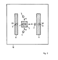
- FIG. 2 shows a plan view of the circuit board 10 with the built-in sensors 1 to 6 and the actuating magnets 7 to 9 arranged above or adjacent thereto.
- the sensors 1 to 4 and the associated actuating magnet 7 are reversed in polarity as are the sensors 5 and 6 with the associated actuating magnets 8 and 9. So those sensors are used which react differently depending on the polarity of the actuating magnet. Hall generators or are used as sensors Magnetic field sensitive resistors are provided.
- the magnet 7 and the magnet 9 are positioned asymmetrically in the (drawn) basic position G above the respective associated sensor. As a result, the sensor 1 and then the sensor 6 switch off when the split magnet 9 is pivoted into the neutral position N.
- Appropriately designed evaluation electronics ensure that an inserted split group remains inserted in the transmission even in the neutral position. The electronics are otherwise designed so that an old position of the shift lever is maintained until a new position has been reliably recognized.
Landscapes
- Engineering & Computer Science (AREA)
- Mechanical Engineering (AREA)
- General Engineering & Computer Science (AREA)
- Chemical & Material Sciences (AREA)
- Combustion & Propulsion (AREA)
- Transportation (AREA)
- Arrangement Or Mounting Of Control Devices For Change-Speed Gearing (AREA)
- Control Of Transmission Device (AREA)
Applications Claiming Priority (2)
| Application Number | Priority Date | Filing Date | Title |
|---|---|---|---|
| DE19843434205 DE3434205A1 (de) | 1984-09-18 | 1984-09-18 | Geber fuer ein schaltgetriebe eines kraftfahrzeugs |
| DE3434205 | 1984-09-18 |
Publications (2)
| Publication Number | Publication Date |
|---|---|
| EP0175061A1 true EP0175061A1 (fr) | 1986-03-26 |
| EP0175061B1 EP0175061B1 (fr) | 1988-08-17 |
Family
ID=6245680
Family Applications (1)
| Application Number | Title | Priority Date | Filing Date |
|---|---|---|---|
| EP85107035A Expired EP0175061B1 (fr) | 1984-09-18 | 1985-06-07 | Transmetteur pour la boîte de vitesse d'un véhicule automobile |
Country Status (3)
| Country | Link |
|---|---|
| US (1) | US4660430A (fr) |
| EP (1) | EP0175061B1 (fr) |
| DE (2) | DE3434205A1 (fr) |
Cited By (6)
| Publication number | Priority date | Publication date | Assignee | Title |
|---|---|---|---|---|
| WO1990002895A1 (fr) * | 1988-09-06 | 1990-03-22 | Automotive Products Plc | Levier de changement de vitesse pour transmission de vehicule |
| WO1990004122A2 (fr) * | 1988-10-12 | 1990-04-19 | Automotive Products Plc | Detecteur de position d'engrenage |
| EP0508224A1 (fr) * | 1991-04-10 | 1992-10-14 | Wagner Fördertechnik GmbH & Co KG | Poignée rotative combinée pour la commande à deux mains d'un chariot élévateur guidé |
| FR2692956A1 (fr) * | 1992-06-29 | 1993-12-31 | Peugeot | Dispositif de détection de la position et/ou du changement de position d'un levier de manÓoeuvre. |
| EP0620385A1 (fr) * | 1993-04-13 | 1994-10-19 | Jaeger | Ensemble de commande pour boîte de vitesses mécanique et système de commande incorporant celui-ci |
| WO2014166689A1 (fr) * | 2013-04-12 | 2014-10-16 | Zf Friedrichshafen Ag | Dispositif de détection de champ magnétique, dispositif de commande et procédé de détermination d'une position relative |
Families Citing this family (44)
| Publication number | Priority date | Publication date | Assignee | Title |
|---|---|---|---|---|
| JPH01206143A (ja) * | 1988-02-10 | 1989-08-18 | Honda Motor Co Ltd | 自動変速機の変速制御装置 |
| DE3807881A1 (de) * | 1988-03-10 | 1989-09-21 | Porsche Ag | Schaltvorrichtung fuer ein automatikgetriebe eines kraftfahrzeugs |
| US4998450A (en) * | 1988-04-29 | 1991-03-12 | Chrysler Corporation | Neutral start switch to sense shift lever position |
| DE3924318A1 (de) * | 1989-07-22 | 1991-01-24 | Bayerische Motoren Werke Ag | Schaltung fuer ein kraftfahrzeuggetriebe |
| DE3925064A1 (de) * | 1989-07-28 | 1991-01-31 | Bayerische Motoren Werke Ag | Waehlhebel fuer ein kraftfahrzeuggetriebe |
| IT1241178B (it) * | 1990-02-16 | 1993-12-29 | Fiat Auto Spa | Sistema per il controllo di un cambio automatico per un autoveicolo del tipo comprendente un dispositivo variatore continuo. |
| DE4005588C2 (de) * | 1990-02-22 | 1995-03-23 | Porsche Ag | Schaltvorrichtung für ein automatisches Getriebe |
| US5068583A (en) * | 1990-08-15 | 1991-11-26 | Transportation Technologies, Inc. | Electronic shifter |
| DE4038998C1 (en) * | 1990-12-06 | 1992-05-14 | J I Case Gmbh, 4040 Neuss, De | Vehicle gear transmission position detector - provides safety interlock for transmission to prevent vehicle from starting out of neutral |
| DE4108388C2 (de) * | 1991-03-15 | 2000-10-12 | Wabco Gmbh & Co Ohg | Einrichtung zur berührungslosen Erfassung von mindestens zwei Positionen eines Schaltelementes |
| US5325083A (en) * | 1992-05-01 | 1994-06-28 | Chrysler Corporation | Manual valve position sensing system |
| US5243871A (en) * | 1992-08-13 | 1993-09-14 | Ford New Holland, Inc. | Control lever apparatus for generating electrical control signals |
| DE4233938A1 (de) * | 1992-10-08 | 1994-04-14 | Bayerische Motoren Werke Ag | Schaltvorrichtung für ein durch ein elektronisches Steuergerät gesteuertes automatisches Gebtriebe eines Kraftfahrzeuges |
| DE4236228A1 (de) * | 1992-10-27 | 1994-04-28 | Opel Adam Ag | Vorrichtung zum Erkennen des Schaltzustandes eines Getriebes |
| US5420565A (en) * | 1993-05-26 | 1995-05-30 | Chrysler Corporation | Electronic PRNODDL display system |
| JP2542557B2 (ja) * | 1993-06-18 | 1996-10-09 | 第一電装部品株式会社 | シフトレバ―の不安定位置検出装置 |
| US5514048A (en) * | 1993-10-06 | 1996-05-07 | Case Corporation | Interlocked control lever system with engine starting interlock circuit for an off-highway implement |
| US5532529A (en) * | 1994-11-14 | 1996-07-02 | Caterpillar Inc. | Contactless inductance joystick switch |
| JPH09509730A (ja) * | 1994-12-24 | 1997-09-30 | ルーク ゲトリーベ−ジステーメ ゲゼルシャフト ミット ベシュレンクテル ハフツング | 駆動ユニットと伝動装置との間で有効なトルク伝達系を制御するための装置及び方法 |
| US6073509A (en) * | 1994-12-24 | 2000-06-13 | Luk Getriebe-Systeme Gmbh | Apparatus and method for regulating the operation of a torque transmission system between a driving unit and a transmission in a motor vehicle |
| DE19650154C2 (de) * | 1996-12-04 | 1999-06-10 | Lemfoerder Metallwaren Ag | Schaltvorrichtung für ein Getriebe eines KFZ mit einer mit Sensoren, Leuchtdioden, Prozessen und anderen elektronischen Bauelementen bestückten Leiterplatte und Verfahren zur Herstellung einer gekrümmten Leiterplatte zur Verwendung in einer solchen Schaltvorrichtung |
| SE510069C2 (sv) * | 1997-08-19 | 1999-04-12 | Scandmec Ab | Manöveranordning samt användningen av manöveranordningen i ett motorfordon |
| AT408325B (de) * | 1998-03-13 | 2001-10-25 | Keba Gmbh & Co | Sicherheitsschalteinrichtung für ein handbediengerät zur steuerung von maschinen |
| US6027426A (en) * | 1998-05-28 | 2000-02-22 | Transmission Technologies Corporation | Neutral sensing and shift lever interlock assembly for a vehicular transmission |
| DE19849716A1 (de) | 1998-10-28 | 2000-05-04 | Bayerische Motoren Werke Ag | Übersetzungswahlvorrichtung für ein Fahrzeug |
| DE19902639A1 (de) * | 1999-01-23 | 2000-07-27 | Bayerische Motoren Werke Ag | Schaltsystem |
| US6072390A (en) * | 1999-03-31 | 2000-06-06 | Daimlerchrysler Corporation | Position sensing system for manually operated shift lever of a vehicle transmission |
| CA2346701A1 (fr) * | 1999-08-06 | 2001-02-15 | Michael O'reilly | Systeme de selection de la position engagee de la transmission |
| US6244127B1 (en) | 1999-10-28 | 2001-06-12 | Teleflex, Incorporated | Mechanical or electrical transmission shifter |
| DE10038433B4 (de) * | 2000-08-07 | 2011-12-29 | Volkswagen Ag | Vorrichtung zur Feststellung einer veränderbaren Schaltstellung eines bewegbaren Schaltelementes insbesondere eines Kraftfahrzeugs |
| US6382045B1 (en) | 2000-09-11 | 2002-05-07 | Teleflex Incorporated | Single lever shift assembly for an electronically controlled transmission |
| US6966237B2 (en) * | 2001-04-02 | 2005-11-22 | Zf Meritor, Llc | First gear/reverse gate indicator switch |
| JP4145139B2 (ja) * | 2002-12-26 | 2008-09-03 | 本田技研工業株式会社 | 変速機のギアポジション検知装置の配置構造 |
| US20050030009A1 (en) * | 2003-06-24 | 2005-02-10 | Moreno Daniel J. | Discrete absolute sensor and code |
| DE102004056800A1 (de) * | 2004-11-24 | 2006-06-01 | Zf Friedrichshafen Ag | Schaltvorrichtung für ein Kraftfahrzeug |
| DE102004060771B4 (de) * | 2004-12-17 | 2006-12-21 | Audi Ag | Vorrichtung zum Schalten von Übersetzungsänderungen |
| SE528386C2 (sv) * | 2005-03-08 | 2006-10-31 | Kongsberg Automotive Ab | En anordning för avläsning av position hos växelspaken i ett fordon |
| DE102005044254A1 (de) * | 2005-09-15 | 2007-03-29 | Zf Friedrichshafen Ag | Betätigungseinrichtung mit Zusatzschaltelement |
| US7761254B2 (en) * | 2007-05-11 | 2010-07-20 | Caterpillar Inc | Operator interface assembly including a Hall effect element and machine using same |
| US7701203B2 (en) * | 2007-05-11 | 2010-04-20 | Caterpillar Inc. | Method of sensing a position of a movable component of an operator interface in a machine |
| FR2925139B1 (fr) * | 2007-12-17 | 2010-01-08 | Sc2N Sa | Capteur de position d'une boite de vitesses et boite de vitesses correspondante |
| US9019053B1 (en) * | 2013-12-09 | 2015-04-28 | Raymond Contreras | Multi-position magnetic rotary switch |
| US10107388B2 (en) * | 2015-12-16 | 2018-10-23 | Dura Operating, Llc | Vehicle shifter assembly |
| US11073205B2 (en) | 2019-03-29 | 2021-07-27 | Dus Operating Inc. | Shift lever assembly with position sensing |
Citations (5)
| Publication number | Priority date | Publication date | Assignee | Title |
|---|---|---|---|---|
| DE1630253A1 (de) * | 1966-12-22 | 1971-05-13 | Paul Comment | Handgashebel fuer Kraftfahrzeuge mit Verbrennungsmotoren |
| US3974711A (en) * | 1970-01-05 | 1976-08-17 | Hurst Performance, Inc. | Stick shift assembly |
| US4022078A (en) * | 1976-04-05 | 1977-05-10 | Clark Equipment Company | Shift control mechanism |
| DE2460769B2 (de) * | 1974-12-21 | 1980-05-29 | Audi Nsu Auto Union Ag, 7107 Neckarsulm | Lagerung für einen Schalthebel in einem Kraftfahrzeug |
| DE3138827A1 (de) * | 1981-09-30 | 1983-04-14 | Wabco Westinghouse Fahrzeugbremsen GmbH, 3000 Hannover | Gangwaehler fuer ein getriebe |
Family Cites Families (7)
| Publication number | Priority date | Publication date | Assignee | Title |
|---|---|---|---|---|
| DE1104834B (de) * | 1956-10-01 | 1961-04-13 | Norbert Riedel | Kontaktgeber fuer elektromagnetisch schaltbare Zahnraederwechselgetriebe, insbesondere fuer Kraftfahrzeuge |
| US4199747A (en) * | 1978-06-15 | 1980-04-22 | Scott Miller | Transmission shift-position indicating system for motor trucks |
| DE2937140C2 (de) * | 1979-09-13 | 1986-08-14 | Zahnradfabrik Friedrichshafen Ag, 7990 Friedrichshafen | Schalthebelanordnung |
| US4380938A (en) * | 1981-03-12 | 1983-04-26 | American Standard Inc. | Combination transmission gear selector valve for automotive vehicles |
| NO148986C (no) * | 1981-10-05 | 1984-01-25 | Ole Molaug | Anordning ved robotmanipulator |
| DE3237509A1 (de) * | 1982-10-09 | 1984-04-12 | Wabco Westinghouse Fahrzeugbremsen GmbH, 3000 Hannover | Gangschaltung fuer ein fremdkraftbetaetigtes getriebe |
| DE3237508A1 (de) * | 1982-10-09 | 1984-04-19 | Wabco Westinghouse Fahrzeugbremsen GmbH, 3000 Hannover | Gangschaltung fuer ein fremdkraftbetaetigtes getriebe |
-
1984
- 1984-09-18 DE DE19843434205 patent/DE3434205A1/de not_active Withdrawn
-
1985
- 1985-06-07 DE DE8585107035T patent/DE3564399D1/de not_active Expired
- 1985-06-07 EP EP85107035A patent/EP0175061B1/fr not_active Expired
- 1985-09-16 US US06/776,250 patent/US4660430A/en not_active Expired - Lifetime
Patent Citations (5)
| Publication number | Priority date | Publication date | Assignee | Title |
|---|---|---|---|---|
| DE1630253A1 (de) * | 1966-12-22 | 1971-05-13 | Paul Comment | Handgashebel fuer Kraftfahrzeuge mit Verbrennungsmotoren |
| US3974711A (en) * | 1970-01-05 | 1976-08-17 | Hurst Performance, Inc. | Stick shift assembly |
| DE2460769B2 (de) * | 1974-12-21 | 1980-05-29 | Audi Nsu Auto Union Ag, 7107 Neckarsulm | Lagerung für einen Schalthebel in einem Kraftfahrzeug |
| US4022078A (en) * | 1976-04-05 | 1977-05-10 | Clark Equipment Company | Shift control mechanism |
| DE3138827A1 (de) * | 1981-09-30 | 1983-04-14 | Wabco Westinghouse Fahrzeugbremsen GmbH, 3000 Hannover | Gangwaehler fuer ein getriebe |
Cited By (12)
| Publication number | Priority date | Publication date | Assignee | Title |
|---|---|---|---|---|
| WO1990002895A1 (fr) * | 1988-09-06 | 1990-03-22 | Automotive Products Plc | Levier de changement de vitesse pour transmission de vehicule |
| GB2240595A (en) * | 1988-09-06 | 1991-08-07 | Automotive Products Plc | A gear lever for a vehicle transmission |
| GB2240595B (en) * | 1988-09-06 | 1992-07-01 | Automotive Products Plc | A gear lever for a vehicle transmission |
| WO1990004122A2 (fr) * | 1988-10-12 | 1990-04-19 | Automotive Products Plc | Detecteur de position d'engrenage |
| WO1990004122A3 (fr) * | 1988-10-12 | 1990-07-12 | Automotive Products Plc | Detecteur de position d'engrenage |
| GB2242488A (en) * | 1988-10-12 | 1991-10-02 | Automotive Products Plc | Gear position sensor |
| GB2242488B (en) * | 1988-10-12 | 1992-09-09 | Automotive Products Plc | Gear position sensor |
| EP0508224A1 (fr) * | 1991-04-10 | 1992-10-14 | Wagner Fördertechnik GmbH & Co KG | Poignée rotative combinée pour la commande à deux mains d'un chariot élévateur guidé |
| FR2692956A1 (fr) * | 1992-06-29 | 1993-12-31 | Peugeot | Dispositif de détection de la position et/ou du changement de position d'un levier de manÓoeuvre. |
| EP0620385A1 (fr) * | 1993-04-13 | 1994-10-19 | Jaeger | Ensemble de commande pour boîte de vitesses mécanique et système de commande incorporant celui-ci |
| FR2703958A1 (fr) * | 1993-04-13 | 1994-10-21 | Jaeger | Ensemble de commande pour boîte de vitesses mécanique et système de commande incorporant celui-ci. |
| WO2014166689A1 (fr) * | 2013-04-12 | 2014-10-16 | Zf Friedrichshafen Ag | Dispositif de détection de champ magnétique, dispositif de commande et procédé de détermination d'une position relative |
Also Published As
| Publication number | Publication date |
|---|---|
| DE3434205A1 (de) | 1986-03-27 |
| DE3564399D1 (en) | 1988-09-22 |
| EP0175061B1 (fr) | 1988-08-17 |
| US4660430A (en) | 1987-04-28 |
Similar Documents
| Publication | Publication Date | Title |
|---|---|---|
| EP0175061B1 (fr) | Transmetteur pour la boîte de vitesse d'un véhicule automobile | |
| EP1045172B1 (fr) | Dispositif de commande pour une boíte de vitesses automatique de véhicule automobile | |
| EP0656492B1 (fr) | Disposition de levier de commande d'une boite de vitesses | |
| DE4005588C2 (de) | Schaltvorrichtung für ein automatisches Getriebe | |
| DE4426207C5 (de) | Wähleinrichtung für ein Automatikgetriebe eines Kraftfahrzeugs | |
| DE60209848T2 (de) | Schaltsperre-Vorrichtung | |
| EP0416227B1 (fr) | Transmission pour véhicule automobile | |
| DE19959616A1 (de) | Steuereinrichtung für ein automatisch und manuell schaltbares Schaltgetriebe in einem Kraftfahrzeug | |
| DE4447512A1 (de) | Fahrstufenwähleinrichtung für ein automatisches Kraftfahrzeuggetriebe | |
| DE102010037954A1 (de) | Getriebeschaltvorrichtung für ein Fahrzeug | |
| DE102006034939A1 (de) | Schaltvorrichtung für ein automatisiertes oder automatisches Getriebe | |
| EP1611375B1 (fr) | Changement de vitesses du type shift-by-wire avec position p | |
| DE19633948A1 (de) | Wähleinrichtung für ein Automatikgetriebe eines Kraftfahrzeugs | |
| EP1488140B1 (fr) | Dispositif de selection pour commander la selection de rapports d'une boite de vitesses d'automobile | |
| DE19849076A1 (de) | Wähleinrichtung für ein automatisch geschaltetes Getriebe eines Kraftfahrzeugs | |
| DE19811972C2 (de) | Wählvorrichtung für ein Automatikgetriebe eines Kraftfahrzeuges | |
| DE3048371A1 (de) | Zweirichtungsschalter | |
| DE2851694C3 (de) | Schalteranordnung für eine elektronische Uhr | |
| DE19850374A1 (de) | Kraftfahrzeug mit einer Wähleinrichtung für ein automatisch geschaltetes Getriebe | |
| DE202004021616U1 (de) | Vorrichtung zum manuellen Schalten eines Automatikgetriebes | |
| DE19961375A1 (de) | Fahrstufenschaltvorrichtung für ein Automatikgetriebe | |
| DE19941795C1 (de) | Automatikschaltgriff mit Druckmechanismus | |
| DE19855951A1 (de) | Automatisiertes Drehmomentübertragungssystem für Kraftfahrzeuge | |
| DE112006000491T5 (de) | Schalthebel mit zusätzlicher Detektion | |
| DE102006017857A1 (de) | Getriebeanordnung |
Legal Events
| Date | Code | Title | Description |
|---|---|---|---|
| PUAI | Public reference made under article 153(3) epc to a published international application that has entered the european phase |
Free format text: ORIGINAL CODE: 0009012 |
|
| AK | Designated contracting states |
Kind code of ref document: A1 Designated state(s): DE FR GB IT SE |
|
| 17P | Request for examination filed |
Effective date: 19860206 |
|
| 17Q | First examination report despatched |
Effective date: 19870108 |
|
| GRAA | (expected) grant |
Free format text: ORIGINAL CODE: 0009210 |
|
| AK | Designated contracting states |
Kind code of ref document: B1 Designated state(s): DE FR GB IT SE |
|
| ITF | It: translation for a ep patent filed |
Owner name: JACOBACCI & PERANI S.P.A. |
|
| REF | Corresponds to: |
Ref document number: 3564399 Country of ref document: DE Date of ref document: 19880922 |
|
| ET | Fr: translation filed | ||
| GBT | Gb: translation of ep patent filed (gb section 77(6)(a)/1977) | ||
| PLBE | No opposition filed within time limit |
Free format text: ORIGINAL CODE: 0009261 |
|
| STAA | Information on the status of an ep patent application or granted ep patent |
Free format text: STATUS: NO OPPOSITION FILED WITHIN TIME LIMIT |
|
| 26N | No opposition filed | ||
| ITTA | It: last paid annual fee | ||
| EAL | Se: european patent in force in sweden |
Ref document number: 85107035.9 |
|
| REG | Reference to a national code |
Ref country code: GB Ref legal event code: IF02 |
|
| PGFP | Annual fee paid to national office [announced via postgrant information from national office to epo] |
Ref country code: GB Payment date: 20020605 Year of fee payment: 18 |
|
| PGFP | Annual fee paid to national office [announced via postgrant information from national office to epo] |
Ref country code: SE Payment date: 20020612 Year of fee payment: 18 |
|
| PGFP | Annual fee paid to national office [announced via postgrant information from national office to epo] |
Ref country code: FR Payment date: 20020627 Year of fee payment: 18 |
|
| PG25 | Lapsed in a contracting state [announced via postgrant information from national office to epo] |
Ref country code: GB Free format text: LAPSE BECAUSE OF NON-PAYMENT OF DUE FEES Effective date: 20030607 |
|
| PG25 | Lapsed in a contracting state [announced via postgrant information from national office to epo] |
Ref country code: SE Free format text: LAPSE BECAUSE OF NON-PAYMENT OF DUE FEES Effective date: 20030608 |
|
| GBPC | Gb: european patent ceased through non-payment of renewal fee |
Effective date: 20030607 |
|
| EUG | Se: european patent has lapsed | ||
| PG25 | Lapsed in a contracting state [announced via postgrant information from national office to epo] |
Ref country code: FR Free format text: LAPSE BECAUSE OF NON-PAYMENT OF DUE FEES Effective date: 20040227 |
|
| REG | Reference to a national code |
Ref country code: FR Ref legal event code: ST |
|
| PGFP | Annual fee paid to national office [announced via postgrant information from national office to epo] |
Ref country code: DE Payment date: 20040605 Year of fee payment: 20 |