EP0174492A2 - Stromregelventil - Google Patents
Stromregelventil Download PDFInfo
- Publication number
- EP0174492A2 EP0174492A2 EP85109772A EP85109772A EP0174492A2 EP 0174492 A2 EP0174492 A2 EP 0174492A2 EP 85109772 A EP85109772 A EP 85109772A EP 85109772 A EP85109772 A EP 85109772A EP 0174492 A2 EP0174492 A2 EP 0174492A2
- Authority
- EP
- European Patent Office
- Prior art keywords
- flow control
- control valve
- valve body
- disc
- plate
- Prior art date
- Legal status (The legal status is an assumption and is not a legal conclusion. Google has not performed a legal analysis and makes no representation as to the accuracy of the status listed.)
- Granted
Links
Images

Classifications
-
- F—MECHANICAL ENGINEERING; LIGHTING; HEATING; WEAPONS; BLASTING
- F16—ENGINEERING ELEMENTS AND UNITS; GENERAL MEASURES FOR PRODUCING AND MAINTAINING EFFECTIVE FUNCTIONING OF MACHINES OR INSTALLATIONS; THERMAL INSULATION IN GENERAL
- F16K—VALVES; TAPS; COCKS; ACTUATING-FLOATS; DEVICES FOR VENTING OR AERATING
- F16K17/00—Safety valves; Equalising valves, e.g. pressure relief valves
- F16K17/20—Excess-flow valves
- F16K17/22—Excess-flow valves actuated by the difference of pressure between two places in the flow line
- F16K17/24—Excess-flow valves actuated by the difference of pressure between two places in the flow line acting directly on the cutting-off member
- F16K17/28—Excess-flow valves actuated by the difference of pressure between two places in the flow line acting directly on the cutting-off member operating in one direction only
- F16K17/30—Excess-flow valves actuated by the difference of pressure between two places in the flow line acting directly on the cutting-off member operating in one direction only spring-loaded
-
- G—PHYSICS
- G05—CONTROLLING; REGULATING
- G05D—SYSTEMS FOR CONTROLLING OR REGULATING NON-ELECTRIC VARIABLES
- G05D7/00—Control of flow
- G05D7/01—Control of flow without auxiliary power
- G05D7/0126—Control of flow without auxiliary power the sensing element being a piston or plunger associated with one or more springs
Definitions
- the invention relates to a flow control valve according to the preamble of the main claim.
- a flow control valve has the disadvantage that it controls the flow of the pressure medium depending on the pressure.
- the flow control valve according to the invention with the characterizing features of the main claim has the advantage that it is simple and compact.
- the amount of pressure medium can be kept constant regardless of the pressure. No complex and expensive finishing is necessary.
- the sealing ring With the help of the sealing ring, the disc is centered and sealed at the same time.
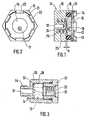
- FIG. 1 shows a longitudinal section through a flow control valve
- FIG. 2 shows a front view of the same
- FIG. 3 shows a longitudinal section through a modification of the exemplary embodiment according to FIG. 1
- FIG. 4 shows a second modification
- FIG. 5 shows a front view of the exemplary embodiment according to FIG. 4.
- a central, once stepped drain hole 12 is formed in a housing 10 of a flow control valve 11. This opens into a cylindrical recess 13 which is open towards one end 14 of the housing 10.
- a throttle plate 15 is arranged in the recess 13 and is mounted on its outer circumference in a sealing ring 16. This is biased radially, so that the throttle plate 15 is centered in its position in the recess 13 and sealed at the same time.
- the throttle plate 15 has an off-center stepped bore 17 serving as an orifice plate, the bore part 18 facing the drain bore 12 of which has the smaller diameter.
- the drain hole 12 and the stepped hole 17 are arranged so that they are neither aligned nor intersect.
- the throttle plate 15 lies with its end facing away from the drain hole 12 against a stop ring 21 arranged in the opening of the recess 13 and has a play a in the recess 13.
- the stop ring 21 is fastened by six flanged edge sections 22 formed at a distance of approximately 60 ° from one another in the edge of the housing 10.
- annular space 23 is formed in the housing 10, which opens into the recess 13.
- the longitudinal axis of the annular space 23 coincides with the axis of the drain hole 12.
- the transition 24 from the annular space 23 to the recess 13 is chamfered.
- a compression spring 25 which, with one end, abuts the throttle plate 15 centrally and presses it against the stop ring 21.
- the throttle plate 15 bears against the stop ring 21 due to the force of the compression spring 25.
- the pressure drops at the stepped bore 17 serving as a measuring orifice.
- the effective pressure difference between the pressures acting on the two end faces of the throttle plate 15 displaces the throttle plate 15 against the force of the compression spring 25 toward the drain hole 12.
- the play a becomes smaller, so that the discharge of the pressure medium from the recess 13 through the drain hole 12 is throttled.
- the drain hole 12, the compression spring 25 and the throttle plate 15 act together as a so-called pressure compensator. This enables a constant pressure medium flow regardless of the pressure acting in each case. Any pressure fluctuations at a connected consumer can be compensated for.
- the flow control valve 11 is arranged in the interior 28 of a cup-shaped housing part 29.
- the opening of the recess 13 of the flow control valve 11 faces the bottom 30 of the housing part 29.
- the housing part 29 has an extension 34 extending from the bottom 30 in which a through bore 31 opening into the bottom 30 is formed.
- a second housing part 32 is screwed into the opening of the housing part 29 and has a central, continuous bore 33.
- the housing part 32 is screwed into the housing part 29 so far that the housing 10 of the flow control valve 11 is movable in the longitudinal direction. Furthermore, it is arranged with a radial clearance b in the interior 28 of the housing part 29.
- the housing 10 of the flow control valve 11 is displaced by the pressure of the pressure medium toward the bottom 30 of the housing part 29 and bears against it.
- the pressure medium now flows largely unthrottled both via the radial clearance b and between the flanged edge portions 22 of the housing 10 to the bore 31 and to a lesser extent through the housing 10 of the flow control valve 11.
- This makes it possible to restrict the pressure medium flow in one direction - from the Bore 31 to bore 33 - to be limited to a constant amount.
- a free, almost unrestricted flow of the pressure medium is possible. Is this arrangement e.g. installed in a lifting device, it is possible to quickly raise the lifting device and lower it at a lowering speed limited by the flow control valve 11.
- a throttle plate 36 arranged in the sealing ring 16 has a central pin 37 facing away from the drain hole 12. In the end there is a slot 38, the edges 39 of which are flanged outwards.
- an eccentric stepped bore 40 is formed, the bore part 41 of which faces the drain bore 12 with the larger diameter.
- a disc 42 is arranged, the central bore 43 has the same diameter as the pin 37.
- the second disk 45 lies on the edges 39 and the first disk 42 on the throttle plate 36.
- a crescent-shaped recess 46 is formed in the area of the stepped bore 40 in the disk 42. Their maximum diameter corresponds to the diameter of the stepped bore 40 in the throttle plate 36.
- a tab 47 by means of which the disk 42 can be displaced relative to the throttle plate 36, for example with the aid of a screwdriver.
- the throttle plate 36 is held in place with the aid of a second screwdriver engaging in the slot 38.
- a scale 48 is attached to the disk 45, with the aid of which the uncovered opening of the stepped bore 40 can be calibrated. If the disk 42 is rotated relative to the throttle plate 36, the opening width of the stepped bore 40 is continuously changed from completely closed to completely open. As a result, any flow of pressure medium and thus any lowering speed of a connected consumer can be set.
Landscapes
- Engineering & Computer Science (AREA)
- General Engineering & Computer Science (AREA)
- Physics & Mathematics (AREA)
- General Physics & Mathematics (AREA)
- Automation & Control Theory (AREA)
- Mechanical Engineering (AREA)
- Safety Valves (AREA)
- Sliding Valves (AREA)
Abstract
Description
- Die Erfindung geht aus von einem Stromregelventil nach der Gattung des Hauptanspruchs. Ein derartiges, bekanntes Stromregelventil hat den Nachteil, daß es den Durchfluß des Druckmittels jeweils abhängig vom Druck regelt.
- Das erfindungsgemäße Stromregelventil mit den kennzeichnenden Merkmalen des Hauptanspruchs hat demgegenüber den Vorteil, daß es einfach und kompakt baut. Die Druckmittelmenge kann unabhängig vom Druck konstant gehalten werden. Es sind keine aufwendigen und teueren Feinbearbeitungen notwendig. Mit Hilfe des Dichtrings ist die Scheibe gleichzeitig zentriert und auch abgedichtet.
- Durch die in den Unteransprüchen aufgeführten Maßnahmen sind vorteilhafte Weiterbildungen und Verbesserungen der im Hauptanspruch angegebenen Merkmale möglich.
- Insbesondere nach Anspruch 5 ist es möglich, die Durchflußrichtung in einer Richtung zu regeln, während in der entgegengesetzten Richtung freier und weitgehend ungedrosselter Durchfluß möglich ist. Dadurch kann ein angeschlossener Verbraucher z.B. in der einen Richtung schnell angehoben und in der anderen Richtung langsam abgesenkt werden. Nach den Ansprüchen 6 bis 10 ist es ferner möglich, die Durchflußgröße des Druckmittels durch die Meßblende von außen her einzustellen. Dadurch sind beliebige Druckmittelströme möglich, so daß ein Verbraucher mit unterschiedlichen Absenkgeschwindigkeiten gesteuert werden kann.
- Zeichnung
- Ein Ausführungsbeispiel der Erfindung ist in der Zeichnung dargestellt und in der nachfolgenden Beschreibung näher erläutert. Es zeigen Figur 1 einen Längsschnitt durch ein Stromregelventil, Figur 2 eine Vorderansicht desselben, Figur 3 einen Längsschnitt durch eine Abwandlung des Ausführungsbeispiels nach Figur 1, Figur 4 eine zweite Abwandlung und Figur 5 eine Vorderansicht des Ausführungsbeispiels nach Figur 4.
- Beschreibung des Ausführungsbeispiels
- In einem Gehäuse 10 eines Stromregelventils 11 ist eine mittige, einmal abgesetzte Abflußbohrung 12 ausgebildet. Diese mündet in eine zylindrische Ausnehmung 13, die zur einen Stirnseite 14 des Gehäuses 10 hin geöffnet ist. In der Ausnehmung 13 ist eine Drosselplatte 15 angeordnet, die an ihrem Außenumfang in einem Dichtring 16 gelagert ist. Dieser ist radial vorgespannt, so daß die Drosselplatte 15 in ihrer Lage in der Ausnehmung 13 zentriert und gleichzeitig abgedichtet ist. Die Drosselplatte 15 weist eine außermittige, als Meßblende dienende Stufenbohrung 17 auf, deren der AbTlußbohrung 12 zugewandtes Bohrungsteil 18 den kleineren Durchmesser hat. Die Abflußbohrung 12 und die Stufenbohrung 17 sind so angeordnet, daß sie weder fluchten noch sich schneiden. Die Drosselplatte 15 liegt mit ihrer der Abflußbohrung 12 abgewandten Stirnseite an einem in der Öffnung der Ausnehmung 13 angeordneten Anschlagring 21 an und hat in der Ausnehmung 13 ein Spiel a. Der Anschlagring 21 ist durch sechs im Abstand von ca. 60° voneinander im Rand des Gehäuses 10 ausgebildeten Bördelkantenabschnitte 22 befestigt.
- Im Bereich der Abflußbohrung 12 ist im Gehäuse 10 ein Ringraum 23 ausgebildet, der in die Ausnehmung 13 mündet. Die Längsachse des Ringraums 23 fällt mit der Achse der Abflußbohrung 12 zusammen. Der Übergang 24 vom Ringraum 23 zur Ausnehmung 13 ist angeschrägt. Im Ringraum 23 befindet sich eine Druckfeder 25, die mit ihrem einen Ende zentrisch an der Drosselplatte 15 anliegt und diese gegen den Anschlagring 21 drückt.
- Strömt kein Druckmittel durch das Gehäuse 10 des Stromregelventils 11, so liegt die Drosselplatte 15 durch die Kraft der Druckfeder 25 am Anschlagring 21 an. Sobald Druckmittel durch das Stromregelventil 11 fließt, fällt an der als Meßblende dienenden Stufenbohrung 17 der Druck ab. Der wirksame Druckunterschied der auf die beiden Stirnseiten der Drosselplatte 15 wirkenden Drücke verschiebt die Drosselplatte 15 entgegen der Kraft der Druckfeder 25 zur Abflußbohrung 12 hin. Je weiter der Druckmittelstrom ansteigt, desto größer wird der wirksame Druckunterschied und somit die Kraft auf die Druckfeder 25. Dadurch wird das Spiel a kleiner, so daß der Abfluß des Druckmittels von der Ausnehmung 13 durch die Abflußbohrung 12 angedrosselt wird. Je mehr die Drosselplatte 15 zur Abflußbohrung 12 hin verschoben wird, desto stärker ist das abströmende Druckmittel angedrosselt. Die Abflußbohrung 12, die Druckfeder 25 und die Drosselplatte 15 wirken zusammen als sogenannte Druckwaage. Dadurch ist ein konstanter Druckmittelfluß unabhängig vom jeweils wirkenden Druck möglich. Es können eventuelle Druckschwankungen an einem angeschlossenen Verbraucher ausgeglichen werden.
- Im Ausführungsbeispiel nach Figur 3 ist das Stromregelventil 11 im Innern 28 eines becherförmigen Gehäuseteils 29 angeordnet. Die Öffnung der Ausnehmung 13 des Stromregelventils 11 ist dabei dem Boden 30 des Gehäuseteils 29 zugewandt. Das Gehäuseteil 29 hat einen vom Boden 30 ausgehenden Fortsatz 34 in dem eine im Boden 30 mündende durchgehende Bohrung 31 ausgebildet ist. In die Öffnung des Gehäuseteils 29 ist ein zweites Gehäuseteil 32 eingeschraubt, das eine mittige, durchgehende Bohrung 33 aufweist. Das Gehäuseteil 32 ist soweit in das Gehäuseteil 29 eingeschraubt, daß das Gehäuse 10 des Stromregelventils 11 in Längsrichtung beweglich ist. Ferner ist es mit einem radialen Spiel b im Innern 28 des Gehäuseteils 29 angeordnet.
- Strömt das Druckmittel über die Bohrung 31 in das Innere 28 des Gehäuseteils 29, so wird das Gehäuse 10 des Stromregelventils 11 vom Druck des Druckmittels an das Gehäuseteil 32 angedrückt. Dadurch ist kein Druckmittelfluß über das radiale Spiel b möglich, und das gesamte Druckmittel fließt - wie oben beschrieben - durch das Gehäuse 10 des Stromregelventils 11 in die Bohrung 33.
- Strömt das Druckmittel in entgegengesetzter Richtung, also von der Bohrung 33 zur Bohrung 31, so wird das Gehäuse 10 des Stromregelventils 11 vom Druck des Druckmittels zum Boden 30 des Gehäuseteils 29 hin verschoben und liegt an diesem an. Das Druckmittel strömt nun weitgehend ungedrosselt sowohl über das radiale Spiel b und zwischen die Bördelkantenabschnitte 22 des Gehäuses 10 zur Bohrung 31 als auch zu einem kleineren Teil durch das Gehäuse 10 des Stromregelventils 11. Dadurch ist es möglich, den Druckmittelfluß in einer Richtung - von der Bohrung 31 zur Bohrung 33 - auf eine konstante Menge zu begrenzen. In der entgegengesetzten Richtung - von der Bohrung 33 zur Bohrung 31 - ist ein freier, nahezu ungedrosselter Durchfluß des Druckmittels möglich. Ist diese Anordnung z.B. in einer Hubvorrichtung eingebaut, so ist es möglich, die Hubvorrichtung schnell anzuheben und mit einer durch das Stromregelventil 11 begrenzten Absenkgeschwindigkeit abzusenken.
- Das Ausführungsbeispiel nach Figur 4 entspricht weitgehend dem Ausführungsbeispiel nach Figur 1. Entsprechende Bauteile sind wieder mit gleichen Ziffern bezeichnet. Eine im Dichtring 16 angeordnete Drosselplatte 36 hat einen mittigen, der Abflußbohrung 12 abgewandten Zapfen 37. In dessen Ende befindet sich ein Schlitz 38, dessen Kanten 39 nach außen umgebördelt sind. In der Drosselplatte 36 ist eine außermittige Stufenbohrung 40 ausgebildet, deren Bohrungsteil 41 mit dem größeren Durchmesser der Abflußbohrung 12 zugewandt ist. Auf dem Zapfen 37 der Drosselplatte 36 ist eine Scheibe 42 angeordnet, deren mittige Bohrung 43 denselben Durchmesser wie der Zapfen 37 hat. An dieser Scheibe 42 befinden sich zwei federnde Lappen 44, die sich mit ihrem einen Ende an eine zweite, auf dem Zapfen 37 angeordneten Scheibe 45 anlegen. Dadurch liegt die zweite Scheibe 45 an den Kanten 39 und die erste Scheibe 42 an der Drosselplatte 36 an. Ferner ist im Bereich der Stufenbohrung 40 in der Scheibe 42 eine sichelförmige Ausnehmung 46 ausgebildet. Ihr maximaler Durchmesser entspricht dabei dem Durchmesser der Stufenbohrung 40 in der Drosselplatte 36. Am Rand der Scheibe 42 ist ein Lappen 47 angeordnet, durch den z.B. mit Hilfe eines Schraubenziehers die Scheibe 42 relativ zur Drosselplatte 36 verschoben werden.kann. Dabei wird die Drosselplatte 36 mit Hilfe eines zweiten in den Schlitz 38 eingreifenden Schraubenziehers festgehalten. Im Bereich der sichelförmigen Ausnehmung 46 ist an der Scheibe 45 eine Skala 48 angebracht, mit deren Hilfe die nicht überdeckte Öffnung der Stufenbohrung 40 geeicht werden kann. Wird die Scheibe 42 relativ zur Drosselplatte 36 verdreht, so wird die Öffnungsweite der Stufenbohrung 40 von völlig geschlossen bis völlig geöffnet stufenlos verändert. Dadurch ist ein beliebiger Druckmittelfluß und somit eine beliebige Absenkgeschwindigkeit eines angeschlossenen Verbrauchers einstellbar.
Claims (10)
Applications Claiming Priority (2)
| Application Number | Priority Date | Filing Date | Title |
|---|---|---|---|
| DE3433424 | 1984-09-12 | ||
| DE19843433424 DE3433424A1 (de) | 1984-09-12 | 1984-09-12 | Stromregelventil |
Publications (3)
| Publication Number | Publication Date |
|---|---|
| EP0174492A2 true EP0174492A2 (de) | 1986-03-19 |
| EP0174492A3 EP0174492A3 (en) | 1987-05-06 |
| EP0174492B1 EP0174492B1 (de) | 1991-03-20 |
Family
ID=6245182
Family Applications (1)
| Application Number | Title | Priority Date | Filing Date |
|---|---|---|---|
| EP19850109772 Expired - Lifetime EP0174492B1 (de) | 1984-09-12 | 1985-08-03 | Stromregelventil |
Country Status (2)
| Country | Link |
|---|---|
| EP (1) | EP0174492B1 (de) |
| DE (2) | DE3433424A1 (de) |
Cited By (4)
| Publication number | Priority date | Publication date | Assignee | Title |
|---|---|---|---|---|
| DE19806451A1 (de) * | 1998-02-17 | 1999-08-19 | Huthmann | Durchflußmengenregler |
| EP1067322A3 (de) * | 1999-06-16 | 2002-09-04 | Robert Bosch Gmbh | Stromregelventil |
| WO2008019863A1 (de) * | 2006-08-17 | 2008-02-21 | Trw Automative Gmbh | Hydraulikventil sowie hydraulikkreislauf mit einem solchen hydraulikventil |
| WO2013050871A1 (en) * | 2011-10-07 | 2013-04-11 | Toyota Jidosha Kabushiki Kaisha | Flow control valve |
Families Citing this family (2)
| Publication number | Priority date | Publication date | Assignee | Title |
|---|---|---|---|---|
| DE3836112A1 (de) * | 1988-10-22 | 1990-04-26 | Teves Gmbh Alfred | Regelventil, insbesondere fuer schlupfgeregelte hydraulische bremsanlagen |
| GB2390413A (en) * | 2002-07-05 | 2004-01-07 | Jason Hydraulics Ltd | An adjustable hydraulic flow control valve |
Family Cites Families (5)
| Publication number | Priority date | Publication date | Assignee | Title |
|---|---|---|---|---|
| DE7116557U (de) * | 1972-10-05 | Siemens Ag | Durchflußmengenregler | |
| US2816572A (en) * | 1955-01-17 | 1957-12-17 | Guardian Electric Mfg Co | Flow control device |
| DE1034488B (de) * | 1956-10-31 | 1958-07-17 | Westinghouse Bremsen Gmbh | Sicherungsvorrichtung bei der Luftfederungsanlage an Kraftfahrzeugen |
| DE7428678U (de) * | 1974-08-24 | 1975-02-13 | Kraenzle J | Druckschaltventil |
| DE3246899A1 (de) * | 1982-12-17 | 1984-06-20 | Paul Pleiger Maschinenfabrik, 5810 Witten | Ventil |
-
1984
- 1984-09-12 DE DE19843433424 patent/DE3433424A1/de not_active Withdrawn
-
1985
- 1985-08-03 DE DE8585109772T patent/DE3582210D1/de not_active Expired - Lifetime
- 1985-08-03 EP EP19850109772 patent/EP0174492B1/de not_active Expired - Lifetime
Cited By (4)
| Publication number | Priority date | Publication date | Assignee | Title |
|---|---|---|---|---|
| DE19806451A1 (de) * | 1998-02-17 | 1999-08-19 | Huthmann | Durchflußmengenregler |
| EP1067322A3 (de) * | 1999-06-16 | 2002-09-04 | Robert Bosch Gmbh | Stromregelventil |
| WO2008019863A1 (de) * | 2006-08-17 | 2008-02-21 | Trw Automative Gmbh | Hydraulikventil sowie hydraulikkreislauf mit einem solchen hydraulikventil |
| WO2013050871A1 (en) * | 2011-10-07 | 2013-04-11 | Toyota Jidosha Kabushiki Kaisha | Flow control valve |
Also Published As
| Publication number | Publication date |
|---|---|
| DE3433424A1 (de) | 1986-03-20 |
| EP0174492A3 (en) | 1987-05-06 |
| EP0174492B1 (de) | 1991-03-20 |
| DE3582210D1 (de) | 1991-04-25 |
Similar Documents
| Publication | Publication Date | Title |
|---|---|---|
| DE2116395C3 (de) | Hydraulische Steuerventileinrichtung für einen Servomotor | |
| DE2813618C2 (de) | Elektromagnetisch betätigtes Druckregelventil | |
| DE68903457T2 (de) | Rueckschlagventil. | |
| EP0321774A2 (de) | Schiebeventil mit Mengenregulierung | |
| EP1741843B1 (de) | Systemtrenner | |
| DE3831554C2 (de) | Drosselrückschlagventil | |
| EP0174492B1 (de) | Stromregelventil | |
| DE1425595C3 (de) | Einrichtung zur Dampfung von Druck stoßen mit einem Nadelventil | |
| DE3840013C2 (de) | Sicherheitsventil | |
| EP0041247B1 (de) | Vorgesteuerte Vorrichtung zur lastunabhängigen Volumenstromregelung | |
| DE1122788B (de) | Hahn mit am Kueken beweglich gelagertem Abschlussteil und im Gehaeuse verschiebbar gelagertem Dichtsitzring | |
| DE3438077C2 (de) | ||
| DE3831644C2 (de) | Hydraulisch dämpfendes Lager | |
| EP0222858B1 (de) | Rohrtrenner | |
| DE2060279A1 (de) | UEberstroemventil | |
| DE3420890C2 (de) | ||
| DE2032859B2 (de) | Durchflussmengenregler | |
| DE2254263A1 (de) | Sicherheitsventil | |
| DE3006231A1 (de) | Hydraulisches ventil | |
| CH665697A5 (de) | Rohrtrenner. | |
| DE2161260C3 (de) | Thermostatisch gesteuertes Regelventil | |
| DE3515573C2 (de) | ||
| DE19626324A1 (de) | Sicherheitsventileinrichtung | |
| DE19927392A1 (de) | Stromregelventil | |
| EP0387524A2 (de) | 2-Wege-Stromventil |
Legal Events
| Date | Code | Title | Description |
|---|---|---|---|
| PUAI | Public reference made under article 153(3) epc to a published international application that has entered the european phase |
Free format text: ORIGINAL CODE: 0009012 |
|
| 17P | Request for examination filed |
Effective date: 19850803 |
|
| AK | Designated contracting states |
Kind code of ref document: A2 Designated state(s): DE FR GB IT |
|
| PUAL | Search report despatched |
Free format text: ORIGINAL CODE: 0009013 |
|
| AK | Designated contracting states |
Kind code of ref document: A3 Designated state(s): DE FR GB IT |
|
| 17Q | First examination report despatched |
Effective date: 19880317 |
|
| GRAA | (expected) grant |
Free format text: ORIGINAL CODE: 0009210 |
|
| AK | Designated contracting states |
Kind code of ref document: B1 Designated state(s): DE FR GB IT |
|
| ET | Fr: translation filed | ||
| GBT | Gb: translation of ep patent filed (gb section 77(6)(a)/1977) | ||
| REF | Corresponds to: |
Ref document number: 3582210 Country of ref document: DE Date of ref document: 19910425 |
|
| ITF | It: translation for a ep patent filed | ||
| PGFP | Annual fee paid to national office [announced via postgrant information from national office to epo] |
Ref country code: GB Payment date: 19910729 Year of fee payment: 7 |
|
| PGFP | Annual fee paid to national office [announced via postgrant information from national office to epo] |
Ref country code: FR Payment date: 19910829 Year of fee payment: 7 |
|
| PLBE | No opposition filed within time limit |
Free format text: ORIGINAL CODE: 0009261 |
|
| STAA | Information on the status of an ep patent application or granted ep patent |
Free format text: STATUS: NO OPPOSITION FILED WITHIN TIME LIMIT |
|
| RAP4 | Party data changed (patent owner data changed or rights of a patent transferred) |
Owner name: ROBERT BOSCH GMBH |
|
| 26N | No opposition filed | ||
| PG25 | Lapsed in a contracting state [announced via postgrant information from national office to epo] |
Ref country code: GB Effective date: 19920803 |
|
| PGFP | Annual fee paid to national office [announced via postgrant information from national office to epo] |
Ref country code: DE Payment date: 19921029 Year of fee payment: 8 |
|
| GBPC | Gb: european patent ceased through non-payment of renewal fee |
Effective date: 19920803 |
|
| PG25 | Lapsed in a contracting state [announced via postgrant information from national office to epo] |
Ref country code: FR Effective date: 19930430 |
|
| REG | Reference to a national code |
Ref country code: FR Ref legal event code: ST |
|
| PG25 | Lapsed in a contracting state [announced via postgrant information from national office to epo] |
Ref country code: DE Effective date: 19940503 |