EP0171586B2 - Friction brake for vehicle-trailer couplings - Google Patents
Friction brake for vehicle-trailer couplings Download PDFInfo
- Publication number
- EP0171586B2 EP0171586B2 EP85108347A EP85108347A EP0171586B2 EP 0171586 B2 EP0171586 B2 EP 0171586B2 EP 85108347 A EP85108347 A EP 85108347A EP 85108347 A EP85108347 A EP 85108347A EP 0171586 B2 EP0171586 B2 EP 0171586B2
- Authority
- EP
- European Patent Office
- Prior art keywords
- coupling
- trailer
- arms
- ball
- friction brake
- Prior art date
- Legal status (The legal status is an assumption and is not a legal conclusion. Google has not performed a legal analysis and makes no representation as to the accuracy of the status listed.)
- Expired - Lifetime
Links
Images


Classifications
-
- B—PERFORMING OPERATIONS; TRANSPORTING
- B60—VEHICLES IN GENERAL
- B60D—VEHICLE CONNECTIONS
- B60D1/00—Traction couplings; Hitches; Draw-gear; Towing devices
- B60D1/24—Traction couplings; Hitches; Draw-gear; Towing devices characterised by arrangements for particular functions
- B60D1/242—Traction couplings; Hitches; Draw-gear; Towing devices characterised by arrangements for particular functions for supporting braking actions, e.g. braking means integrated with hitches; Braking sensors
-
- B—PERFORMING OPERATIONS; TRANSPORTING
- B60—VEHICLES IN GENERAL
- B60D—VEHICLE CONNECTIONS
- B60D1/00—Traction couplings; Hitches; Draw-gear; Towing devices
- B60D1/01—Traction couplings or hitches characterised by their type
- B60D1/06—Ball-and-socket hitches, e.g. constructional details, auxiliary devices, their arrangement on the vehicle
- B60D1/065—Ball-and-socket hitches, e.g. constructional details, auxiliary devices, their arrangement on the vehicle characterised by the hitch mechanism
-
- B—PERFORMING OPERATIONS; TRANSPORTING
- B60—VEHICLES IN GENERAL
- B60D—VEHICLE CONNECTIONS
- B60D1/00—Traction couplings; Hitches; Draw-gear; Towing devices
- B60D1/24—Traction couplings; Hitches; Draw-gear; Towing devices characterised by arrangements for particular functions
- B60D1/30—Traction couplings; Hitches; Draw-gear; Towing devices characterised by arrangements for particular functions for sway control, e.g. stabilising or anti-fishtail devices; Sway alarm means
- B60D1/32—Traction couplings; Hitches; Draw-gear; Towing devices characterised by arrangements for particular functions for sway control, e.g. stabilising or anti-fishtail devices; Sway alarm means involving damping devices
Definitions
- the invention relates to a vehicle trailer hitch with a friction brake, consisting of a coupling ball and a ball coupling housing comprising this, partial sections of the inner surface of the ball coupling housing having mutually opposite recesses, in which friction brake blocks are arranged, which can be pressed by actuating elements against the surface of the coupling ball , wherein the recesses of the ball coupling housing are designed as circular openings, in which the friction brake pads are piston-like, floating, guided by the inside surfaces of the openings, held under elastic spring pressure.
- Friction brakes of this type serve to dampen vibrations that occur within the degrees of freedom of movement of the coupling ball housing around the ball while both vehicles are traveling in train mode and are manifested in yaw-pitching and rolling movements, so-called rolling movements.
- GB-A-1 380 051 also discloses two further forms of vehicle trailer coupling design in which the friction brake blocks are spring-loaded.
- the ball coupling housing consists of hinge-like housing halves which enclose the coupling ball and which themselves act as friction brake blocks. The friction force is applied symmetrically and constantly to the coupling ball with the aid of friction surfaces which are provided on the inside directly on the housing halves themselves.
- the two interconnected halves of the coupling ball housing not only transmit the frictional forces elastically to the coupling ball, but at the same time must be firmly locked together so that the actual coupling function of the ball coupling housing between vehicle and trailer is reliably ensured.
- the invention has for its object to improve the generic design of a vehicle trailer hitch so that the friction brake pads are not only constantly pressurized during operation and their different wear is taken into account by automatic adjustment, but also the possibility of easy operation and adjustability of this Friction brake blocks is created from the outside.
- the friction brake pads have the carrier, which can be acted upon symmetrically on the back by the arms of a collet, which comprise an arch, the front circumferential side of the ball coupling housing, firmly connected to this clamp and at the ends of the caliper arms exists, and in which known adjusting, clamping and fixing elements are arranged between the tong arms.
- This arrangement and design of a pair of pliers on the ball coupling housing in addition to a simple design, provides easy access to the actuating elements for setting and maintenance of the actuating, tensioning and fixing elements, since these are likewise arranged outside the ball coupling housing.
- parts of the coupling ball can be designed as counter friction surfaces for the friction surfaces of the friction brake pads.
- the carriers of the friction brake pads can be expediently detachably connected to the arms of the collet.
- the actuating, tensioning and fixing elements can also have a motor drive with remote control and display and also a quick release device known per se. "
- the friction brake according to the invention has an effective damping of all vibrations within the degrees of freedom of the already with low coefficients of friction of 0.2 to 0.3 and relatively low application pressures in single-axle trailer vehicles, particularly in the weight class 0.75-3 t Ball coupling achieved. These effects were affected to a small extent by a wet or greasy surface of the coupling ball. Since the friction brake is located on the coupling ball housing on the drawbar of the trailer vehicle, it is also possible to adjust the size of the friction brake pads to the weight of the trailer vehicle, while the corresponding coupling ball on the tractor vehicle can always be the same.
- the setting and fixing elements between the arms of the clamping fork or collet arranged on the coupling housing can consist of a threaded spindle with a scale marking indicating the set pressure or from a wedge adjustment.
- the spindle can also be driven by remote control, whereby the set pressure can be read off via remote display in the towing vehicle. It is also conceivable to change the setting as a function of the respective speed of the towing vehicle using an automatic system.
- the arms can be biased by springs or gas springs and the quick release device can consist of a known toggle lever lock.
- the coupling socket consists of a U-bracket, the U-web of which forms the spherical section-shaped support surface
- a wedge-shaped sliding wedge arranged in the ball coupling housing can act on the back of the web of the U-bracket with its wedge surface.
- the sliding wedge can be arranged at the lower end of a push rod guided in a sleeve extension standing on the extension of the ball coupling housing, the other end of which carries a thread which is seated in a rotating nut mounted on the sleeve extension, the sliding wedge is supported on the back by a slide stop arranged in the ball coupling housing.
- the rotating nut can have one or more single-arm radial adjusting levers. Furthermore, there is the possibility of making the sliding wedge displaceable and fixable relative to the push rod in its longitudinal axis. As the invention further provides, the sliding wedge can also be brought to the rear of the web of the U-bracket via the adjusting elements of the coupling socket in and out of the loading position.
- the design of the friction brake can, as the invention further provides, be developed in such a way that a uniform, constant pressure of the arms of the collet on the friction brake blocks is maintained under the above-mentioned stresses and this pressure does not undergo any significant change due to the wear of the friction brake blocks.
- the clamping elements consist of gas springs which press the ends of the arms of the collet away from one another.
- the clamping elements consist of gas springs which press the ends of the arms of the collet away from one another.
- the center sections of the arms are angled and crosswise one above the other and pass into approximately parallel end sections.
- the arms can also be designed as two-armed levers with a swivel joint arranged in a region between the center of the coupling ball and the ends of the arms.
- the gas spring between the ends of the arms of the collet maintains the contact pressure of the friction brake pads on the counter friction surface of the coupling ball even with shock loads due to its shock absorber effect and does not change this pressure even if the distance between the two ends of the arms of the collet changes due to the wear of the Friction pads of the friction brake pads enlarged.
- the gas spring is articulated to the end section of one of the arms in the embodiments of the friction brake described above and can be releasably inserted with the other end into a recess which forms an articulated eye which is open on one side.
- To open this connection of the two arms i.e. To release the friction brake, it is necessary with this design to compress the gas spring by hand and remove one end of it from the hinge eye. This handling sometimes brings difficulties for the user, especially if the housing of the gas spring is wet or coated with greasiness.
- this type of construction forces the gas spring with its bumper to be articulated firmly to one end section and to attach the joint pin intended for the open joint eye to the cylinder end of the spring.
- the steering axis of the two-armed lever which can be brought into and out of the dead center position can be supported in a bearing block which can be pivoted at a radial distance about a bearing pin-shaped extension of the end sections of the arms, this bearing pin-shaped extension about an approximately perpendicular to the bearing pin axis Axis is pivotally hinged to the end portions of the arms, wherein the bearing pin-shaped extension can consist of a bearing pin placed on a U-link hinged to the end portions.
- a hand lever can be used, which is pivotally mounted in the bearing block about an axis approximately perpendicular to the handlebar axis.
- a further possibility of arranging the arm is to arrange a hand lever lying approximately parallel to the longitudinal axis of the gas spring outside the end sections of both arms.
- This design allows the end sections of the two arms, which are pushed apart by the gas spring via the two-armed lever in the dead center position of the articulation point of the lever and acted upon by the tension of the gas spring, by simply pivoting the two-armed lever by means of the hand lever while overcoming the dead center position from the application pressure relieve the gas spring and open the articulated connection.
- the connection can be established and secured just as easily by pivoting the two-armed lever into the dead center position.
- the coupling ball housing 2 comprising the coupling ball 1, here circularly shaped, opposite openings 2a, in which the friction brake pads 4 on the inner side walls of the openings 2a with their circular disk-shaped carriers 5 whose inner side walls are guided like a piston.
- the surface 4a of the brake blocks 4 which acts on the surface of the coupling ball 1 is curved in a concave manner in the manner of a spherical segment.
- the outwardly facing circular surface of the carrier 5 of the friction brake pads 4 is acted upon (see FIG.
- both gun arms 6 are connected here by a threaded spindle with a threaded nut 10, a lever clamp 12 and the biasing spring 13.
- the lever clamp 13 consists of a clamping lever 14 which is pivotally connected to a double bracket 16 by means of pivot pin 15, which can be pivoted with a spacer pin 17 into a coupling recess 6c of the pincer arm 6 facing away from the spindle 9.
- the tensioning lever 14 In the direction away from the spindle 9, at a distance from the rotary bolts 15, the tensioning lever 14 has a clamping stop piece 18, which is bolt-shaped here and which, in the direction of the center axis of the spindle 9, in a slot guide pair 19 provided in the frame 20 carrying the spindle nut 10 in the direction of the center axis of the spindle 9 is movable back and forth.
- the clamping stop piece 18 is acted upon by the biasing spring 13, which is supported in the frame 20 carrying the spindle nut 10.
- the tensioning lever 14 can be pivoted from the tensioning position shown in full lines in FIG. 2 into the end tensioning position indicated by dash-dotted lines around the spacer bolt 17, the double bracket 16 moving into the end position 16 'and the tensioning stop piece 18 in the slot guide 19 a - here lower - position in the direction of the spindle 19 out in the upper position 18 ', so that the bias spring 13 relaxes and thus also the pressure of the curved lugs 6a, the caliper arms 6 on the carrier 5 of the friction brake pads 4 is canceled becomes.
- the span length of the biasing spring which can be adjusted in the tensioned position of the lever tension lock 12 by turning the spindle or the spindle nut 10, is readable by a scale 21 arranged on the frame 20 and a display wedge 23 arranged on a cover plate 22 of the biasing spring 13.
- a return leg spring 24 placed around the axle pin of the joint 7 of the caliper arm 6 acts on the rear side of the carrier 5 for the friction brake blocks 4 and thus prevents the friction brake blocks 4 from slipping out of the openings 2a of the coupling ball housing 2 that guide them.
- the coupling ball housing 2 has a rear extension 2d in or on which the actuating and adjusting elements 41, 42 and 43 are arranged, with the aid of which the coupling socket 45 points to the coupling ball (not shown) and can be moved and locked away from it.
- the coupling socket 45 is designed here as the web of a U-bracket (FIG. 2) with the bracket arms 45a.
- the coupling socket 45 has a friction-enhancing surface of the spherical section-shaped contact surface 45b and also the inner surface 2m of the coupling ball housing 2 opposite this surface.
- a sleeve extension 47 is fixedly mounted on the extension 2d of the coupling ball housing, in which a push rod 48 is slidably mounted on the lower one End carries a sliding wedge 49, the wedge surface 49a of which can be placed against the rear of the coupling socket 45 and which is supported on the back by a sliding stop 50 projecting between the bracket arms 45b on the extension 2d of the ball coupling housing 2.
- the push rod 48 has at its upper end a thread 48a which is seated in a rotary nut 51 which rotatably supports in the sleeve shoulder 47 and has a radial adjusting lever 52.
- the push rod 45 can be turned by turning the rotating nut 51 Moved upward in the direction of the arrow shown and thus the coupling socket 45 is pressed against the coupling ball via the sliding wedge 49 and its wedge surface 49a.
- the contact pressure can be increased or decreased according to the respective requirements.
- the Push rod 45 with the sliding wedge 49 are initially moved so far downwards against the direction of the arrow mentioned by turning the rotating nut 51 that the 45 can move backwards (to the right in the drawing) into its starting position before the vehicle clutch then moves can be solved.
- the sliding wedge 49 can also be arranged in a manner not shown in such a way that it can be displaced and fixed relative to the push rod 48 in its longitudinal axis, i.e. he can then from a position determined by the position of the rotary nut 51 z. B. push the drawn down and thus the retraction path of the coupling socket 45 are released.
- the sliding wedge 49 can then be brought back into the (drawn) position relative to the push rod 45 in that he was before.
- Such a movement of the sliding wedge 49 can also be connected to the movement of the elements 40, 41, 42 via corresponding connecting levers in the form of a positive control.
- the coupling ball housing 2 comprising the coupling ball 1 has circular, opposing openings 2a, in which the friction brake blocks 4 on the inside walls of the openings 2a are guided in a piston-like manner with their circular-shaped carriers 5 on their inside walls .
- the surface 4a of the friction brake pads 4 which acts on the surface of the coupling ball 1 is curved in a concave manner in the manner of a spherical segment.
- the outwardly facing circular surfaces of the two carriers 5 of the friction brake blocks 4 are acted upon by the curved lugs 6a of the initial sections 6 'of the two caliper arms 6.
- These initial sections 6 ' are articulated in a region in front of the center M of the coupling ball 1 and laterally thereof with swivel joints 7, here at the ends of a clamp 8 firmly connected to the ball coupling housing.
- the central sections 6 "of both tong arms 6 are angled crosswise one above the other and merge into approximately parallel end sections 6" '. Between the two end sections 6 "'there is the gas spring 10, the bumper 10a and the cylinder housing 10b of which is connected in an articulated manner to one or the other end section 6"' of the tong arms 6, one of these articulated connections, here that of the cylinder housing 10b , is releasably insertable into a U-recess 6b.
- the position of the caliper arms 6 shown in full lines corresponds to the position which results when fresh friction brake pads 4 are not yet worn, the distance between the two end sections 6 ′′ then corresponds to the smallest distance, and the position of the caliper arms 6 shown in broken lines shows a distance D2, which sets in when the wear of the brake pads has reached its greatest level.
- the coupling ball housing 2 which comprises the coupling ball 1 has circular, opposite openings 2a, in which the friction brake blocks 4 on the inner side walls of the openings 2a are guided in a piston-like manner with their circular disk-shaped carriers 5 on the inner sides thereof.
- the surface 4a of the friction brake pads 4 which acts on the surface of the coupling ball 1 is curved in a concave manner in the manner of a spherical segment.
- the outwardly facing circular surfaces of the two carriers 5 of the friction brake blocks 4 are acted upon by the curved lugs 6a of the initial sections 6 'of the two caliper arms 6.
- the two-armed lever 61 there is also a hand lever 63, which is approximately parallel to the central axis of the gas spring 10.
- the one-armed lever 61 can be seen from FIG Solid lines shown closed lines can be pivoted by pivoting the hand lever 63 around the joint formed by the bearing eyelet 6b and the pin 61a while pivoting the joint 60 out of the dead center position into the open position indicated by dash-dotted lines and vice versa.
- a handlebar axis 160 which is connected here to the bumper 110a of the gas spring 110, is mounted in a bearing block 170 which can be pivoted with a radial distance d about a bearing pin 172, which is regarded as an extension of the arm end section 106 ′′ can be and in this embodiment is in turn arranged on a swivel bracket 171, which in turn is pivotable about this arm end portion 106 "'.
- a bearing pin 173 serves as the bearing axis, the axis of which runs approximately perpendicular to the axis of the bearing pin 172.
- Another bearing bracket 174 is attached to the bearing pin 170 in the the hand lever 163 is pivotally mounted about an axle pin 175, the axis of which is approximately perpendicular to both the axis of the bearing pin 172 and that of the bearing pin 173.
- the gas spring 110 inserted into the other arm end section 106 ′′ ′′ is tensioned by pivoting the hand lever 163 from the position ( ⁇ ) to the position (S), the hand lever 163 supporting the bearing block 170 around the bearing pin 172 and - Presses the handlebar axis 160 over the dead center position, with the result that the two arm end sections 106 "'remain pressed apart locked dead center. Subsequently, the hand lever 163 in the bearing bracket 174 is pivoted into the position (R) with the result that the arm lever 163 does not hinder the handling of the operating lever 140 of the trailer coupling.
Description
"Die Erfindung bezieht sich auf eine Fahrzeuganhängerkupplung mit Reibungsbremse, bestehend aus einer Kupplungskugel und einem, diese umfassenden Kugelkupplungsgehäuse, wobei Teilabschnitte der Innenfläche des Kugelkupplungsgehäuses paarweise einander gegenüberliegende Ausnehmungen aufweisen, in denen Reibungsbremsklötze angeordnet sind, die von Stellelementen gegen die Oberfläche der Kupplungskugel andrückbar sind, wobei die Ausnehmungen des Kugelkupplungsgehäuses als kreisförmige Durchbrüche ausgebildet sind, in denen die Reibungsbremsklötze kolbenartig, freischwimmend, von den Innenseitenflächen der Durchbrüche geführt, unter elastischem Feder-Druck gehalten werden.""The invention relates to a vehicle trailer hitch with a friction brake, consisting of a coupling ball and a ball coupling housing comprising this, partial sections of the inner surface of the ball coupling housing having mutually opposite recesses, in which friction brake blocks are arranged, which can be pressed by actuating elements against the surface of the coupling ball , wherein the recesses of the ball coupling housing are designed as circular openings, in which the friction brake pads are piston-like, floating, guided by the inside surfaces of the openings, held under elastic spring pressure. "
Reibungsbremsen dieser Art dienen der Dämpfung von Schwingungen, die innerhalb der Freiheitsgrade der Bewegungsmöglichkeiten des Kupplungskugelgehäuses um die Kugel herum während der Fahrt beider Fahrzeuge im Zugbetrieb auftreten und sich in Gier-Nick- und Wankbewegungen, sog. Schlingerbewegungen äußern.Friction brakes of this type serve to dampen vibrations that occur within the degrees of freedom of movement of the coupling ball housing around the ball while both vehicles are traveling in train mode and are manifested in yaw-pitching and rolling movements, so-called rolling movements.
Es sind zahlreiche Vorschläge zur Ausbildung solcher Reibungsbremsen bekanntgeworden. Gemeinsam ist diesen Ausbildungen, daß ein Paar von außerhalb der Kupplung selbst an der Tragstange der Kupplungskugel oder der Zugstange des Anhängerfahrzeugs angeordneter Träger von Reibklötzen oder -scheiben über Mitnehmerelemente relativ zueinander bewegt wird. Der Reibungsdruck zwischen den Reibklötzen bzw. -scheiben läßt sich mit Hilfe von mechanischen Stellelementen verändern, und häufig sind die Mitnehmerelemente selbst auch als zusätzliche Dämpfungsorgane in Form von Drehstäben, Gasdruck-Stoßdämpfern, Blattfedern o.dgl. ausgebildet ("Stabilisatoren", Kamper + Kaçavan Nr. 6 Ausgabe Juni 1984).Numerous proposals for the formation of such friction brakes have become known. Common to these designs is that a pair of carriers of friction blocks or disks arranged outside the coupling itself on the support rod of the coupling ball or the pull rod of the trailer vehicle are moved relative to one another via driver elements. The friction pressure between the friction blocks or discs can be changed with the help of mechanical adjusting elements, and the driver elements themselves are often also used as additional damping elements in the form of torsion bars, gas pressure shock absorbers, leaf springs or the like. trained ("Stabilizers", Kamper + Kaçavan No. 6 edition June 1984).
Diese Bremsen müssen teilweise zweifach in Tandemanordnung angeordnet werden und bedürfen besonderer Befestigungselemente an der Tragstange der Kupplungskugel und der Zugstange des Anhängerfahrzeugs. Die Befestigungselemente müssen genau justiert werden und erfordern deshalb eine sorgfältige Montage, das gleiche gilt für die Einstellung der Reibkraft, besonders bei der Tandemanordnung, da diese sonst leicht das Gegenteil einer Stabilisierung bewirken kann. Schwierigkeiten und besondere konstruktive Vorkehrungen bereitet auch die Notwendigkeit beim Entkuppeln die entsprechenden Elemente der Reibungsbremse voneinander zu trennen.These brakes sometimes have to be arranged twice in tandem and require special fastening elements on the support rod of the coupling ball and the pull rod of the trailer vehicle. The fasteners must be adjusted precisely and therefore require careful assembly, the same applies to the adjustment of the frictional force, especially in the case of the tandem arrangement, since otherwise this can easily have the opposite effect of stabilization. Difficulties and special constructive measures also create the need to separate the corresponding elements of the friction brake from each other when uncoupling.
Zur Vermeidung eines Teils dieser Schwierigkeiten und Nachteile ist bereits vorgeschlagen worden (DE-A-28 41 746) ein paar von Reibscheiben unterhalb des Trägers der Kupplungskugel um deren vertikale Mittenachse herum drehbar zu lagern und die Mitnahmeelemente für diese Reibscheiben seitlich außen am Kugelkupplungsgehäuse anzuordnen. Auch diese Reibungsbremsenausbildung erfordert zusätzliche Befestigungselemente und eine entsprechende besondere Ausbildung des Trägers der Kupplungskugel am Zugfahrzeug und eine entsprechende angepaßte Ausbildung des Kugelkupplungsgehäuses an der Zugstange des Anhängerfahrzeugs, d.h., die Elemente der Reibungsbremse sind z. T. am Zugfahrzeug und z. T. am Anhängerfahrzeug angeordnet, so daß sich bei wechselnden Anhängerfahrzeugen für dasselbe Zugfahrzeug Anpassungsschwierigkeiten nicht vermeiden lassen. Die Reibungskupplung eignet sich im übrigen nur für die Dämpfung von Bewegungen innerhalb der Achsebenen beider Fahrzeuge der sog. Gierbewegungen.To avoid some of these difficulties and disadvantages, it has already been proposed (DE-A-28 41 746) to mount a pair of friction disks below the carrier of the clutch ball so as to be rotatable about its vertical center axis and to arrange the driving elements for these friction disks on the outside of the side of the ball clutch housing. This friction brake training also requires additional fastening elements and a corresponding special training of the carrier of the coupling ball on the towing vehicle and a correspondingly adapted design of the ball coupling housing on the pull rod of the trailer vehicle, i.e. the elements of the friction brake are e.g. T. on the towing vehicle and z. T. arranged on the trailer vehicle, so that with changing trailer vehicles for the same towing vehicle adjustment difficulties can not be avoided. The friction clutch is otherwise only suitable for damping movements within the axis planes of both vehicles, the so-called yaw movements.
"Weiter sind aus den GB-A-892 952 und DE-U-18 88 887 Vorschläge bekannt, in Teilabschnitten der Innenfläche des Kugelkupplungsgehäuses Ausnehmungen anzuordnen, in die die Reibungsbremsklötze eingesetzt sind. Diese werden nach der GB-A-892 952 von Schraubenbolzen beaufschlagt, die in Ausnehmungen der Rückwand vorgesehene Gewindebohrungen eingeschraubt sind und können dadurch gegen die Außenwand der Kupplungskugel gedrückt werden; während nach der DE-U-18 88 887 die in kreisförmigen Durchbrüchen des Kugelkupplungsgehäuses kolbenartig, frei schwimmend geführten Reibungsbremsklötze von oberhalb der Durchbrüche im Kugelkupplungsgehäuse angeordneten Federpaketen beaufschlagt werden. Diese beiden bekannten Ausbildungen benötigen zwar keine zusätzlichen Befestigungselemente mehr und sind auch geeignet, Bewegungen in verschiedenen Achsebenen der Fahrzeuge zu dämpfen; sie weisen aber bei der Ausbildung nach der GB-A-892 952 den Nachteil auf, daß die notwendige symmetrische Einstellung der jeweilig richtigen Reibungsbremskraft wegen zweier, für sich einzustellender Schraubenbolzen nicht nur schwierig ist, sondern schon nach kurzer Betriebszeit wieder zu Unsymmetrien neigt, weil die Reibungsbremsklötze unterschiedlich beansprucht und deshalb während des Fahrbetriebes abgenutzt werden. Auch das Lösen der Reibungsbremsklötze mittels der beiden Schraubenbolzen ist sehr umständlich und erfordert ggfs. die Zuhilfenahme von Zusatzwerkzeugen. Auch bei der Ausbildung nach der DE-U-18 88 887 ist ebenfalls keine zuverlässige, während des Betriebes gleichbleibende symmetrische Einstellung der Reibungsbremsklötze möglich, weil die voneinander unabhängig beide, den einen und den anderen Reibungsbremsklotz beaufschlagenden Federpakete schwierig aufeinander abzustimmen sind und wegen der geringen Abmaße des für ihre Anbringung verfügbaren Raums oberhalb der Durchbrüche des Kugelkupplungsgehäuses verhältnismäßig klein bemessen werden müssen und deshalb auch nur kleine Druckkräfte aufzubringen vermögen mit der Folge, daß auch bei dieser Ausbildung schon nach kurzer Betriebszeit wieder Unsymmetrien der Reibungsbremskräfte auftreten."Also known from GB-A-892 952 and DE-U-18 88 887 are suggestions for arranging recesses in partial sections of the inner surface of the ball coupling housing, into which the friction brake blocks are inserted. According to GB-A-892 952 these are used for screw bolts acted on, the threaded holes provided in recesses in the rear wall are screwed and can thereby be pressed against the outer wall of the coupling ball; while according to DE-U-18 88 887 the friction brake pads, which are guided in a circular manner in a piston-like manner and floating in a piston-like manner, float freely from above the openings in the ball coupling housing Although these two known designs no longer require additional fastening elements and are also suitable for damping movements in different axis planes of the vehicles, they have the disadvantage in the case of the design according to GB-A-892 952 that the necessary symmetrical egg Adjustment of the correct friction braking force is not only difficult because of two screw bolts that can be set individually, but tends to become asymmetrical again after a short operating time, because the friction brake blocks are subjected to different loads and are therefore worn out during driving. The loosening of the friction brake pads using the two bolts is also very cumbersome and may require the use of additional tools. Also in the design according to DE-U-18 88 887, no reliable symmetrical adjustment of the friction brake pads, which remains constant during operation, is also possible, because the spring assemblies acting independently of one another are difficult to adjust to one another and because of the small number of spring assemblies Dimensions of the space available for their attachment above the openings of the ball coupling housing must be dimensioned relatively small and therefore only small pressure forces can be applied, with the result that even with this design asymmetries of the friction braking forces occur again after a short operating time.
Schließlich sind aus GB-A-1 380 051 noch zwei weitere Ausbildungsformen von Fahrzeuganhängerkupplungen bekannt, bei denen die Reibungsbremsklötze federbeaufschlagt sind. Bei der einen Ausbildungsform besteht das Kugelkupplungsgehäuse aus scharnierartig miteinander verbundenen, die Kupplungskugel einfassenden Gehäusehälften, die selbst als Reibungsbremsklötze wirksam werden. Die Reibungskraft wird mit Hilfe von Reibflächen, die innenseitig unmittelbar an den Gehäusehälften selbst vorgesehen sind, zwar symmetrisch und konstant auf die Kupplungskugel aufgebracht. Es ergibt sich aber der Nachteil, daß die beiden miteinander verbundenen Hälften des Kupplungskugelgehäuses nicht nur die Reibkräfte elastisch auf die Kupplungskugel übertragen, sondern gleichzeitig fest miteinander verriegelt sein müssen, damit die eigentliche Kuppelfunktion des Kugelkupplungsgehäuses zwischen Fahrzeug und Anhänger sicher gewährleistet ist. Da bei dieser Ausbildung der Fahrzeuganhängerkupplung, anders als bei den gattungsgemäßen Ausbildungen mit einteiligem Kugelkupplungsgehäuse und in diesem geführten Reibungsbremsklötzen, die eine der genannten Forderungen immer nur zu Lasten der anderen Forderung erfüllt werden kann, fand diese Ausbildung keine Einführung in die Praxis. Bei der zweiten Ausbildung nach dieser GB-A-1 380 051 ist ebenfalls kein gattungsgemäßes Kugelkupplungsgehäuse vorhanden, sondern nur zwei unterschiedlich angeordnete Reibungsbremsklötze. Der eine ist fest mit dem einen Schenkel eines starren U-Profils verschraubt, während der andere in dem anderen Schenkel dieses U-Profils verschieb- und anstellbar, sowie gegen diesen Schenkel durch ein Federpaket elastisch abgestützt ist. Auch diese Ausbildung bringt den Nachteil mit sich, daß die eigentliche Kuppelfunktion nicht sicher gewährleistet ist, weil die Reibungsbremsklötze allein den Kupplungsschluß gewährleisten müssen; darüber hinaus muß die gesamte Reibungsbremskraft von einem einzigen Federpaket aufgebracht werden, für das auch nur ein beschränkter Raum oberhalb des einen der Reibungsbremsklötze zur Verfügung steht."Finally, GB-A-1 380 051 also discloses two further forms of vehicle trailer coupling design in which the friction brake blocks are spring-loaded. In one embodiment, the ball coupling housing consists of hinge-like housing halves which enclose the coupling ball and which themselves act as friction brake blocks. The friction force is applied symmetrically and constantly to the coupling ball with the aid of friction surfaces which are provided on the inside directly on the housing halves themselves. However, there is the disadvantage that the two interconnected halves of the coupling ball housing not only transmit the frictional forces elastically to the coupling ball, but at the same time must be firmly locked together so that the actual coupling function of the ball coupling housing between vehicle and trailer is reliably ensured. Since, in this design of the vehicle trailer coupling, unlike the generic designs with a one-piece ball coupling housing and friction brake blocks guided in it, one of the requirements mentioned can only be met at the expense of the other requirement, this training was not introduced into practice. In the second embodiment according to this GB-A-1 380 051, there is also no generic ball coupling housing, but only two differently arranged friction brake blocks. One is firmly screwed to one leg of a rigid U-profile, while the other is displaceable and adjustable in the other leg of this U-profile, and is elastically supported against this leg by a spring assembly. This training also has the disadvantage that the actual coupling function is not guaranteed because the friction brake pads alone have to ensure the coupling engagement; moreover, the entire friction braking force must be applied by a single spring assembly, for which there is only a limited space available above one of the friction brake pads. "
"Der Erfindung liegt die Aufgabe zugrunde, die gattungsgemäße Ausbildung einer Fahrzeuganhängerkupplung so zu verbessern, daß die Reibungsbremsklötze während des Fahrbetriebes nicht nur gleichbleibend druckbeaufschlagt werden und deren unterschiedlicher Abnutzung durch automatische Nachstellung Rechnung getragen wird, sondern zusätzlich die Möglichkeit einer leichten Bedien- und Einstellbarkeit dieser Reibungsbremsklötze von außen her geschaffen wird."The invention has for its object to improve the generic design of a vehicle trailer hitch so that the friction brake pads are not only constantly pressurized during operation and their different wear is taken into account by automatic adjustment, but also the possibility of easy operation and adjustability of this Friction brake blocks is created from the outside.
Diese Aufgabe wird dadurch, gelöst, daß die Reibungsbremsklötze die Träger aufweisen, die rückseitig symmetrisch von den Armen einer Spannzange beaufschlagbar sind, die aus einer, die vordere Umfangsseite des Kugelkupplungsgehäuses bogenartig umfassen, fest mit diesem verbundenen Spange und an deren Enden angelenkten Zangen-Armen besteht, und bei der zwischen den Zangenarmen an sich bekannte Stell-, Spann- und Festlegeelemente angeordnet sind. Durch diese Anordnung und Ausbildung einer Zange auf dem Kugelkupplungsgehäuse wird neben einfacher Bauweise eine leichte Zugänglichkeit der Stellelemente für Einstellung und Wartung der Stell-, Spann- und Festlegeelemente geschaffen, da diese ebenfalls außerhalb des Kugelkupplungsgehäuses angeordnet sind. Hinzu kommt dabbbei der Vorteil, daß für diese Elemente große, ggfs. handelsübliche Stell- und Federelemente verwendet werden können; die besonders einfache Bauweise und leichte Zugänglichkeit der Zangenelemente selbst ergibt sich dabei aus der Anwendung und Bauweise der Zange, weil die über die Länge der gesamten Kupplung verlaufenden Zangenarme mit einer entsprechend günstigen Hebelwirkung verwendbar sind und die Gestaltung einer kompakten Ausbildungsform der Kupplung möglich gemacht wird, weil zwischen den Armen der Zange noch genügend Raum für die eigentlichen Bedienelemente der Kupplung selbst verbleibt.This object is achieved in that the friction brake pads have the carrier, which can be acted upon symmetrically on the back by the arms of a collet, which comprise an arch, the front circumferential side of the ball coupling housing, firmly connected to this clamp and at the ends of the caliper arms exists, and in which known adjusting, clamping and fixing elements are arranged between the tong arms. This arrangement and design of a pair of pliers on the ball coupling housing, in addition to a simple design, provides easy access to the actuating elements for setting and maintenance of the actuating, tensioning and fixing elements, since these are likewise arranged outside the ball coupling housing. In addition, there is the advantage that large, possibly commercially available actuating and spring elements can be used for these elements; The particularly simple construction and easy accessibility of the pliers elements themselves results from the application and construction of the pliers, because the pliers arms running over the length of the entire coupling can be used with a correspondingly favorable leverage effect and the design of a compact design of the coupling is made possible, because there is still enough space between the arms of the pliers for the actual operating elements of the coupling itself.
Wie die Erfindung weiter vorsieht, können Teile der Kupplungskugel als Gegenreibflächen für die Reibflächen der Reibungsbremsklötze ausgebildet werden. Ferner können die Träger der Reibungsbremsklötze zweckmäßig lösbar mit den Armen der Spannzange verbunden werden. Die Stell-, Spann- ünd Festlegeelemente können auch einen motorischen Antrieb mit Fernbedienung und -anzeige und auch eine an sich bekannte Schnellösevorrichtung aufweisen."As the invention further provides, parts of the coupling ball can be designed as counter friction surfaces for the friction surfaces of the friction brake pads. Furthermore, the carriers of the friction brake pads can be expediently detachably connected to the arms of the collet. The actuating, tensioning and fixing elements can also have a motor drive with remote control and display and also a quick release device known per se. "
Es hat sich im praktischen Betrieb der erfindungsgemäßen Reibungsbremse gezeigt, daß diese schon mit geringen Reibwerten von 0,2 bis 0,3 und verhältnismäßig geringen Ueaufschlagungsdrucken bei Einachsanhängerfahrzeugen, besonders der Gewichtsklasse 0,75-3 t eine wirksame Dämpfung aller Schwingungen innerhalb der Freiheitsgrade der Kugelkupplung erzielt. Diese Wirkungen wurden, in geringem Maße durch eine nasse oder auch fettige Oberflächenbeschaffenheit der Kupplungskugel, beeinträchtigt. Da sich die Reibungsbremse an dem auf der Zugstange des Anhängerfahrzeugs befindlichen Kupplungskugelgehäuse befindet, ist im übrigen eine Anpassung der Größenordnung der Reibungsbremsklötze an das Gewicht des Anhängerfahrzeugs möglich, während die entsprechende Kupplungskugel am Zugfahrzeug immer die gleiche sein kann. "Die Stell- und Festlegeelemente zwischen den Armen der am Kupplungsgehäuse ..." angeordneten Spanngabel oder Spannzange können aus einer Gewindespindel mit einer den eingestellten Beaufschlagungsdruck anzeigenden Skalenmarkierung bestehen oder aus einer Keilverstellung. Die Spindel kann auch mit Fernbetätigung motorisch angetrieben werden, wobei der eingestellte Beaufschlagungsdruck über Fernanzeige im Zugfahrzeug ablesbar gemacht werden kann. Es ist dabei auch denkbar, die Einstellung in Abhängigkeit von der jeweiligen Geschwindigkeit des Zugfahrzeuges über eine Automatik zu ändern. Die Arme können über Federn oder Gasfedern vorgespannt werden und die Schnellösevorrichtung kann aus einem Kniehebelverschluß bekannter Bauart bestehen. "Diese Ausbildung mit seitlich in Ausnehmungen im Kugelkupplungsgehäuse geführten Trägern der Reibungs-Bremsklötze und die Anordnung der entsprechenden, die Träger beaufschlagenden Stellelemente außen auf dem Kupplungskugelgehäuse bringt es ..." mit sich, daß aufgrund der erforderlichen, verhältnismäßig großen Ausnehmungen im Kupplungskugelgehäuse die Führungsflächen der Träger in den Blenden dieses Gehäuses verhältnismäßig schmal gehalten werden müssen, und daß die Spalte zwischen den Reibungs-Bremsklötzen und den Führungsflächen verschmutzen und bei niedrigen Temperaturen vereisen können.It has been shown in practical operation of the friction brake according to the invention that it has an effective damping of all vibrations within the degrees of freedom of the already with low coefficients of friction of 0.2 to 0.3 and relatively low application pressures in single-axle trailer vehicles, particularly in the weight class 0.75-3 t Ball coupling achieved. These effects were affected to a small extent by a wet or greasy surface of the coupling ball. Since the friction brake is located on the coupling ball housing on the drawbar of the trailer vehicle, it is also possible to adjust the size of the friction brake pads to the weight of the trailer vehicle, while the corresponding coupling ball on the tractor vehicle can always be the same. "The setting and fixing elements between the arms of the clamping fork or collet arranged on the coupling housing ..." can consist of a threaded spindle with a scale marking indicating the set pressure or from a wedge adjustment. The spindle can also be driven by remote control, whereby the set pressure can be read off via remote display in the towing vehicle. It is also conceivable to change the setting as a function of the respective speed of the towing vehicle using an automatic system. The arms can be biased by springs or gas springs and the quick release device can consist of a known toggle lever lock. "This training with laterally recesses in the ball coupling housing carriers of the friction brake pads and the arrangement of the corresponding actuating elements acting on the carrier on the outside of the coupling ball housing brings it ..." that the guide surfaces due to the required, relatively large recesses in the coupling ball housing the carrier in the panels of this housing must be kept relatively narrow, and that the gaps between the friction brake pads and the guide surfaces can become dirty and freeze at low temperatures.
Eine weitere, nicht vom Schutz des Anspruchs 1 erfasste Ausbildung sieht vor, daß die Anordnung solcher Ausnehmungen im Kugelkupplungsgehäuse nicht notwendig ist und die bei Fahrzeug-Anhängerkupplungen der gattungsgemäßen Ausbildung ohnehin vorhandene kugelabschnittförmige Anlagefläche der über Stellelemente radial in Richtung auf die Kupplungskugel zu und von dieser weg beweg- und verriegelbaren Kupplungspfanne als Reibungs-Bremsklotz ausgebildet ist. Zweckmäßig wird dabei die dieser kugelabschnittförmigen Anlagefläche radial gegenüberliegende Innenfläche des Kupplungskugelgehäuses mit einer reibungsverstärkenden Oberfläche versehen. Wenn dabei die Kupplungspfanne aus einem U-Bügel besteht, dessen U-Steg die kugelabschnittförmige Auflagefläche bildet, kann ein im Kugelkupplungsgehäuse verschieb- und verriegelbar angeordneter Gleitkeil mit seiner Keilfläche die Rückseite des Stegs des U-Bügels beaufschlagen. Weist das Kugelkupplungsgehäuse eine rückwärtige Verlängerung auf, dann kann der Gleitkeil am unteren Ende einer in einem auf der Verlängerung des Kugelkupplungsgehäuses aufstehenden Hülsenansatz geführten Schubstange angeordnet sein, deren anderes Ende ein Gewinde trägt, das in einer auf dem Hülsenansatz gelagerten Drehmutter sitzt, wobei der Gleitkeil rückseitig von einem im Kugelkupplungsgehäuse angeordneten Gleitanschlag abgestützt ist. Die Drehmutter kann dabei einen oder mehrere einarmige radiale Stellhebel aufweisen. Weiterhin besteht die Möglichkeit, den Gleitkeil relativ zu der Schubstange in deren Längsachse verschieb- und festlegbar auszubilden. Wie die Erfindung weiter vorsieht, kann der Gleitkeil auch über die Stellelemente der Kupplungspfanne in und außer Beaufschlagungsstellung zu der Rückseite des Steges des U-Bügels bringbar sein.Another, not covered by the protection of
Um den Druck der Arme der Spannzange auf die Reibbremsklötze während der Fahrt, unbeeinflußt von den auftretenden Stößen auf die Kupplungsverbindung möglichst gleichmäßig aufrechtzuerhalten, damit die gewünschte Dämpfung der Schlingerbewegungen in jedem Bewegungszustand von Kupplungsgehäuse und Kupplungskugel erreicht wird, muß sichergestellt werden, daß der je nach den Betriebsbeanspruchungen mehr oder weniger starke Verschleiß der Reibbremsklötze auch dann, wenn schon ein großer Abnutzungsgrad eingetreten ist, keinen wesentlichen Einfluß auf die Größe des Drucks der Zangenarme auf die Reibbremsklötze mit sich bringt.In order to maintain the pressure of the arms of the collet on the friction brake pads while driving, unaffected by the impacts on the coupling connection as evenly as possible, so that the desired damping of the rolling movements is achieved in every movement state of the coupling housing and coupling ball, it must be ensured that depending on the operational stresses more or less severe wear of the friction brake pads, even if a high degree of wear has occurred, does not have any significant influence on the size of the pressure of the caliper arms on the friction brake pads.
Die Ausbildung der Reibungsbremse kann dabei, wie die Erfindung weiter vorsieht, so weitergebildet werden, daß ein gleichmäßiger gleichbleibender Druck der Arme der Spannzange auf die Reibbremsklötze unter den oben erwähnten Beanspruchungen aufrechterhalten wird und dieser Druck auch durch die Abnutzung der Reibbremsklötze keine wesentliche Änderung erfährt.The design of the friction brake can, as the invention further provides, be developed in such a way that a uniform, constant pressure of the arms of the collet on the friction brake blocks is maintained under the above-mentioned stresses and this pressure does not undergo any significant change due to the wear of the friction brake blocks.
Dies kann erfindungsgemäß dadurch erreicht werden, daß die Spannelemente aus Gasfedern bestehen, die die Enden der Arme der Spannzange voneinander wegdrücken. Bei als einarmige Hebel ausgebildeten Armen, deren eines Endenpaar in einem Bereich vor der Mitte der Kupplungskugel und seitlich von dieser abgelenkt ist, gehen die Mittenabschnitte der Arme abgewinkelt kreuzweise übereinanderliegend in etwa parallel verlaufende Endabschnitte über. Die Arme können auch als zweiarmige Hebel mit einem in einem Bereich zwischen der Mitte der Kupplungskugel und den Enden der Arme angeordneten Schwenkgelenk ausgebildet sein.This can be achieved according to the invention in that the clamping elements consist of gas springs which press the ends of the arms of the collet away from one another. In the case of arms designed as one-armed levers, the one end pair of which is deflected in an area in front of the center of the coupling ball and laterally from the latter, the center sections of the arms are angled and crosswise one above the other and pass into approximately parallel end sections. The arms can also be designed as two-armed levers with a swivel joint arranged in a region between the center of the coupling ball and the ends of the arms.
Die Gasfeder zwischen den Enden der Arme der Spannzange hält durch ihre Stoßdämpferwirkung den Auflagedruck der Reibbremsklötze auf die Gegenreibfläche der Kupplungskugel auch bei Stoßbeanspruchungen aufrecht und ändert diesen Druck auch dann nicht, wenn sich der Abstand zwischen den beiden Enden der Arme der Spannzange durch den Verschleiß der Reibungsbeläge der Reibbremsklötze vergrößert.The gas spring between the ends of the arms of the collet maintains the contact pressure of the friction brake pads on the counter friction surface of the coupling ball even with shock loads due to its shock absorber effect and does not change this pressure even if the distance between the two ends of the arms of the collet changes due to the wear of the Friction pads of the friction brake pads enlarged.
Die Gasfeder ist bei den vorstehend beschriebenen Ausbildungsformen der Reibungsbremse am Endabschnitt des einen der Arme angelenkt und mit dem anderen Ende lösbar in eine Ausnehmung einsetzbar, die eine einseitig offene Gelenköse bildet. Zum Öffnen dieser Verbindung der beiden Arme, d.h. zum Lösen der Reibungsbremse ist es bei dieser Ausbildung notwendig, die Gasfeder von Hand zusammenzudrücken und ihr eines Ende aus der Gelenköse herauszunehmen. Diese Handhabung bringt hin und wieder Schwierigkeiten für den Benutzer mit sich insbesondere dann, wenn das Gehäuse der Gasfeder naß oder mit Fettigkeit überzogen ist. Darüber hinaus zwingt diese Art der Konstruktion dazu, die Gasfeder mit ihrer Stoßstange fest an dem einen Endabschnitt anzulenken und den für die offene Gelenköse bestimmten Gelenkzapfen am Zylinderende der Feder anzubringen.The gas spring is articulated to the end section of one of the arms in the embodiments of the friction brake described above and can be releasably inserted with the other end into a recess which forms an articulated eye which is open on one side. To open this connection of the two arms, i.e. To release the friction brake, it is necessary with this design to compress the gas spring by hand and remove one end of it from the hinge eye. This handling sometimes brings difficulties for the user, especially if the housing of the gas spring is wet or coated with greasiness. In addition, this type of construction forces the gas spring with its bumper to be articulated firmly to one end section and to attach the joint pin intended for the open joint eye to the cylinder end of the spring.
Diese Schwierigkeiten lassen sich beseitigen und machen eine leichtere Handhabung der Gasfeder beim Öffnen der Verbindung der beiden Endabschnitte möglich, wenn zwischen der an den Endabschnitt eines der Arme angelenkten Gasfeder und dem Endabschnitt des anderen Armes ein zweiarmiger Hebel angeordnet ist, der einerseits mit einer Lenkachse an die Stoßstange der Gasfeder und andererseits mit der anderen Lenkachse am Endabschnitt des anderen Armes angelenkt ist, wobei die eine Lenkachse an der Gasfeder in und außer Totpunktlage zwischen den beiden Anlenkungen an den Endabschnitten der beiden Arme bringbar ist.These difficulties can be eliminated and make easier handling of the gas spring possible when opening the connection of the two end sections if a two-armed lever is arranged between the gas spring articulated on the end section of one of the arms and the end section of the other arm, which lever has a steering axis the bumper of the gas spring and on the other hand is articulated with the other steering axis on the end section of the other arm, the one steering axis on the gas spring being able to be brought into and out of the dead center position between the two articulations on the end sections of the two arms.
Wie die Erfindung weiter vorsieht, kann dabei die in und außer Totpunktlage bringbare Lenkachse des zweiarmigen Hebels in einem Lagerbock lagern, der mit radialem Abstand um eine lagerbolzenförmige Verlängerung der Endabschnitte der Arme schwenkbar ist, wobei diese lagerbolzenförmige Verlängerung um eine, etwa senkrecht zur Lagerbolzenachse liegende Achse schwenkbar an den Endabschnitten der Arme angelenkt ist, wobei die lagerbolzenförmige Verlängerung aus einem, auf eine an den Endabschnitten angelenkte U-Lasche aufgesetzten Lagerbolzen bestehen kann. Es kann bei dieser Anordnung ein Handhebel verwendet werden, der um eine etwa senkrecht zur Lenkerachse liegende Achse schwenkbar in dem Lagerbock gelagert ist. Eine weitere Möglichkeit der Anordnung des Arms besteht darin, außerhalb der Endabschnitte beider Arme einen etwa parallel zur Längsachse der Gasfeder liegenden Handhebel anzuordnen.As the invention further provides, the steering axis of the two-armed lever which can be brought into and out of the dead center position can be supported in a bearing block which can be pivoted at a radial distance about a bearing pin-shaped extension of the end sections of the arms, this bearing pin-shaped extension about an approximately perpendicular to the bearing pin axis Axis is pivotally hinged to the end portions of the arms, wherein the bearing pin-shaped extension can consist of a bearing pin placed on a U-link hinged to the end portions. In this arrangement, a hand lever can be used, which is pivotally mounted in the bearing block about an axis approximately perpendicular to the handlebar axis. A further possibility of arranging the arm is to arrange a hand lever lying approximately parallel to the longitudinal axis of the gas spring outside the end sections of both arms.
Diese Ausbildungsform erlaubt es, die Endabschnitte der beiden Arme, die durch die Gasfeder über den zweiarmigen Hebel in Totpunktlage des Anlenkpunktes des Hebels auseinandergedrückt und durch die Spannung der Gasfeder beaufschlagt werden, durch einfaches Schwenken des zweiarmigen Hebels mittels des Handhebels unter Überwindung der Totpunktlage vom Beaufschlagungsdruck der Gasfeder zu entlasten und die Gelenkverbindung zu öffnen. Ebenso einfach läßt sich die Verbindung durch Einschwenken des zweiarmigen Hebels in die Totpunktlage herstellen und sichern.This design allows the end sections of the two arms, which are pushed apart by the gas spring via the two-armed lever in the dead center position of the articulation point of the lever and acted upon by the tension of the gas spring, by simply pivoting the two-armed lever by means of the hand lever while overcoming the dead center position from the application pressure relieve the gas spring and open the articulated connection. The connection can be established and secured just as easily by pivoting the two-armed lever into the dead center position.
Die Erfindung wird anhand der in den Zeichnungen dargestellten verschiedenen Ausführungsbeispiele näher erläutert. In der Zeichnung zeigen
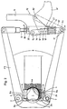
- Fig. 1 die Teilansicht einer Ausbildungsform der Vorrichtung von der Seite gesehen,
- Fig. 2 die teilweise geschnittene Draufsicht auf die Vorrichtung,
- Fig. 3 die Teilansicht eines Schnittes nach der Linie A-A durch Fig. 2,
- Fig. 4 eine andere Ausbildung der Anhängerkupplung im Längsschnitt,
- Fig. 5 die Draufsicht auf Fig. 4 teilweise geschnitten,
- Fig. 6 die Draufsicht auf eine weitere Ausbildungsform der Anhängerkupplung, teilweise geschnitten,
- Fig. 7 eine weitere Ausbildungsform der Anhängerkupplung entsprechend der Darstellung nach Fig. 6,
- Fig. 8 die perspektivische Darstellung einer weiteren Ausbildungsform der Anhängerkupplung von der Seite gesehen und
- Fig. 9 die Anhängerkupplung nach Fig. 8 mit unterschiedlichen Stellungen des Handhebels.
- 1 is a partial view of an embodiment of the device seen from the side,
- 2 shows the partially sectioned top view of the device,
- 3 is a partial view of a section along the line AA through FIG. 2,
- Fig. 4 shows another embodiment of the Towing hitch in longitudinal section,
- 5 is a partially sectioned top view of FIG. 4,
- 6 is a top view of a further embodiment of the trailer coupling, partly in section,
- 7 shows a further embodiment of the trailer coupling corresponding to the representation according to FIG. 6,
- Fig. 8 seen the perspective view of a further embodiment of the trailer coupling from the side and
- Fig. 9, the trailer hitch according to Fig. 8 with different positions of the hand lever.
Wie aus Fig. 1 in Verbindung mit Fig. 2 zu ersehen, weist das die Kupplungskugel 1 umfassende Kupplungskugelgehäuse 2, hier kreisförmig ausgebildete, sich gegenüberliegende Durchbrüche 2a auf, in denen die Reibbremsklötze 4 an den Innenseitenwandungen der Durchbrüche 2a mit ihren kreisscheibenförmigen Trägern 5 an deren Innenseitenwänden kolbenartig geführt sind. Die die Oberfläche der Kupplungskugel 1 beaufschlagende Fläche 4a der Relbbremsklötze 4 ist kugelabschnittsförmig konkav nach innen gewölbt. Die nach außen gewandte Kreisfläche des Trägers 5 der Reibbremsklötze 4 wird (vgl. Fig. 2) von dem gewölbten Ansatz 6a des Zangenarms 6 beaufschlagt, der mit einem Gelenk 7 an dem einen Ende einer mit dem Kugelkupplungsgehäuse 2 fest verbundenen Zangenspange 8 angelenkt ist, deren anderes Ende über ein entsprechende Gelenk 7 mit dem anderen Zangenarm 6 gelenkig verbunden ist. Die freien Enden beider Zangenarme 6 sind hier durch eine Gewindespindel mit Gewindemutter 10, einen Hebelspannverschluß 12 und der Vorspannfeder 13 miteinander verbunden. Der Hebelspannverschluß 13 besteht aus einem Spannhebel 14, der mit Drehbolzen 15 an eine Doppellasche 16 angelenkt ist, die sich mit einem Distanzbolzen 17 in eine Kupplungsausnehmung 6c des der Spindel 9 abgewandten Zangenarms 6 schwenkbar einhängen läßt.As can be seen from FIG. 1 in connection with FIG. 2, the
In Richtung von der Spindel 9 weg, im Abstand von den Drehboozen 15 weist der Spannhebel 14 ein hier bolzenförmiges Spannanschlagstück 18 auf, das in Richtung der Mittenachse der Spindel 9 in einem die Spindelmutter 10 tragenden Rahmen 20 vorgesehenen Schlitzführungspaar 19 in Richtung der Mittenachse der Spindel 9 hin und her beweglich ist.In the direction away from the
Das Spannanschlagstück 18 wird dabei von der Vorspannfeder 13 beaufschlagt, die sich in dem die Spindelmutter 10 tragenden Rahmen 20 abstützt.The clamping
Der Spannhebel 14 kann aus der in Fig. 2 in vollen Linien dargestellten Spannstellung in die in strichpunktierte Linien angedeutete Endspannstellung um den Distanzbolzen 17 schwenkend gebracht werden, wobei sich die Doppellasche 16 in die Endstellung 16' bewegt und das Spannanschlagstück 18 in der Schlitzführung 19 aus einer-hier unteren - Stellung in Richtung auf die Spindel 19 hin in die obere Stellung 18' geführt wird, so daß sich die Vorspannfeder 13 entspannt und damit auch der Druck der gewölbten Ansätze 6a, der Zangenarme 6 auf die Träger 5 der Reibbremsklötze 4 aufgehoben wird. Die Spannlänge der Vorspannfeder, die sich in Spannstellung des Hebelspannverschlusses 12 durch Drehen der Spindel bzw. der Spindelmutter 10 verstellen läßt, wird durch eine am Rahmen 20 angeordnete Skala 21 und einen an einer Abdeckplatte 22 der Vorspannfeder 13 angeordneten Anzeigekeil 23 ablesbar gemacht.The tensioning
Wie aus Fig. 2 weiter hervorgeht, beaufschlagt eine um den Achsbolzen der Gelenkes 7 des Zangenarmes 6 gelegte Rückstellschenkelfeder 24 die Rückseite des Trägers 5 für die Reibbremsklötze 4 und verhindert damit ein Herausrutschen der Reibbremsklötze 4 aus den diese führenden Durchbrüchen 2a des Kupplungskugelgehäuses 2.As can further be seen from FIG. 2, a
Beim Ausführungsbeispiel nach den Fig. 4 und 5 weist das Kupplungskugelgehäuse 2 eine rückwärtige Verlängerung 2d in bzw. auf der die Betätigungs- und Stellelemente 41, 42 und 43 angeordnet sind, mit deren Hilfe die Kupplungspfanne 45 auf die (nicht dargestellte) Kupplungskugel zu und von dieser weg beweg- und verriegelbar ist. Die Kupplungspfanne 45 ist hier als der Steg eines U-Bügels (Fig. 2) mit den Bügelarmen 45a ausgebildet. Die Kupplungspfanne 45 weist eine reibungsverstärkende Oberfläche der kugelabschnittsförmigen Anlagefläche 45b auf und ebenso die dieser Fläche gegenüberliegende Innenfläche 2m des Kupplungskugelgehäuses 2. Weiter ist auf der Verlängerung 2d des Kupplungskugelgehäuses ein Hülsenansatz 47 aufstehend befestigt, in dem eine Schubstange 48 gleitend gelagert ist, die am unteren Ende einen Gleitkeil 49 trägt, dessen Keilfläche 49a an die Rückseite der Kupplungspfanne 45 anlegbar ist und der rückseitig von einem an der Verlängerung 2d des Kugelkupplungsgehäuses 2 zwischen die Bügelarme 45b ragenden Gleitanschlag 50 abgestützt ist. Die Schubstange 48 weist an ihrem oberen Ende ein Gewinde 48a auf, das in einer Drehmutter 51 sitzt, die in den Hülsenansatz 47 drehbar lagert und einen radialen Stellhebel 52 aufweist.In the embodiment according to FIGS. 4 and 5, the
Nachdem das Kupplungskugelgehäuse 2 auf die (nicht dargestellte) Kupplungskugel des Anhängerfahrzeugs aufgesetzt worden ist und die Kupplungspfanne 45 mit Hilfe der Stellelemente 40, 41, 42 auf die Kupplungskugel hin in die dargestellte Kupplungslage gebracht wurde, kann durch Drehen der Drehmutter 51 die Schubstange 45 in Richtung des dargestellten Pfeils nach oben bewegt und damit die Kupplungspfanne 45 über den Gleitkeil 49 und dessen Keilfläche 49a gegen die Kupplungskugel gedrückt werden. Der Anpreßdruck läßt sich dabei den jeweiligen Erfordernissen entsprechend vergrößern oder verkleinern. Zum Lösen der Fahrzeugkupplung muß dann die Schubstange 45 mit dem Gleitkeil 49 zunächst entgegen der Richtung des genannten Pfeils durch Drehen der Drehmutter 51 so weit nach unten bewegt werden, daß sich die 45 nach hinten (in der Zeichnung nach rechts) in ihre Ausgangsstellung zurück bewegen kann, ehe sich dann die Fahrzeugkupplung lösen läßt.After the
Um diesen Vorgang zu vereinfachen, kann der Gleitkeil 49 auch auf nicht dargestellte Weise so angeordnet werden, daß er sich relativ zur Schubstange 48 in deren Längsachse verschieben und festlegen läßt, d.h. er kann dann aus einer durch die Stellung der Drehmutter 51 bestimmten Lage z. B. der gezeichneten nach unten wegstoßen und damit der Rückzugweg der Kupplungspfanne 45 freigegeben werden. Nach Wiederaufsetzen des Kupplungskugelgehäuses, 2 auf eine Kupplungskugel und das Einfahren der Kupplungspfanne 45 in die entsprechende Verriegelungsstellung nach Betätigung der Elemente 40, 41, 42 kann der Gleitkeil 49 dann durch Hochziehen relativ zur Schubstange 45 wieder in die (gezeichnete) Stellung eingebracht werden, in der er sich vorher befand. Eine solche Bewegung des Gleitkeils 49 läßt sich auch über entsprechende Verbindungshebel in Form einer Zwangssteuerung mit der Bewegung der Elemente 40, 41, 42 verbinden.In order to simplify this process, the sliding
Wie aus Fig. 6 zu ersehen, weist bei diesem Ausführungsbeispiel das die Kupplungskugel 1 umfassende Kupplungskugelgehäuse 2 kreisförmig ausgebildete, sich gegenüberliegende Durchbrüche 2a auf, in denen die Reibbremsklötze 4 an den Innenseitenwandungen der Durchbrüche 2a mit ihren kreisscheibenförmigen Trägern 5 an deren Innenseitenwänden kolbenartig geführt sind. Die die Oberfläche der Kupplungskugel 1 beaufschlagende Fläche 4a der Reibbremsklötze 4 ist kugelabschnittsförmig konkav nach innen gewölbt. Die nach außen gewandten Kreisflächen der beiden Träger 5 der Reibbremsklötze 4 wird von den gewölbten Ansätzen 6a der Anfangsabschnitte 6' der beiden Zangenarme 6 beaufschlagt. Diese Anfangsabschnitte 6' sind in einem Bereich vor der Mitte M der Kupplungskugel 1 und seitlich von dieser mit Schwenkgelenken 7, hier an den Enden einer mit dem Kugelkupplungsgehäuse fest verbundenen Zangenspange 8 angelenkt.As can be seen from FIG. 6, in this exemplary embodiment, the
Die Mittenabschnitte 6" beider Zangenarme 6 liegen abgewinkelt kreuzweise übereinander und gehen in etwa parallel verlaufende Endabschnitte 6"' über. Zwischen den beiden Endabschnitten 6"' befindet sich die Gasfeder 10, deren Stoßstange 10a und deren Zylindergehäuse 10b jeweils mit dem einen bzw. dem anderen Endabschnitt 6"' der Zangenarme 6 gelenkig verbunden ist, wobei die eine dieser Gelenkverbindungen, hier die des Zylindergehäuses 10b, lösbar in eine U-Ausnehmung 6b einschiebbar ist.The
Die in vollen Linien wiedergegebene Stellung der Zangenarme 6 entspricht der Stellung, die sich bei noch nicht abgenutzten frischen Reibbremsklötzen 4 ergibt, der Abstand zwischen den beiden Endabschnitten 6"' entspricht dann dem geringsten Abstand, und die strichpunktiert wiedergegebene Stellung der Zangenarme 6 weist einen Abstand D2 auf, der sich einstellt, wenn die Abnutzung der Reibbremsklötze ihr größtes Maß erreicht hat.The position of the
Beim Ausführungsbeispiel nach Fig. 7 weist das die Kupplungskugel 1 umfassende Kupplungskugelgehäuse 2 kreisförmig ausgebildete sich gegenüberliegende Durchbrüche 2a auf, in denen die Reibungsbremsklötze 4 an den Innenseitenwandungen der Durchbrüche 2a mit ihren kreisscheibenförmigen Trägern 5 an deren Innenseiten kolbenartig geführt sind. Die die Oberfläche der Kupplungskugel 1 beaufschlagende Fläche 4a der Reibungsbremsklötze 4 ist kugelabschnittsförmig konkav nach innen gewölbt. Die nach außen gewandten Kreisflächen der beiden Träger 5 der Reibbremsklötze 4 werden von den gewölbten Ansätzen 6a der Anfangsabschnitte 6' der beiden Zangenarme 6 beaufschlagt. Diese Anfangsabschnitte 6' sind in einem Bereich vor der Mitte M der Kupplungskugel 1 seitlich von dieser mit Schwenkgelenken 7 hier an den Enden einer mit dem Kugelkupplungsgehäuse fest verbundenen Zangenspange 8 angelenkt. Die Mittenabschnitte 6" beider Zangenarme 6 liegen abgewinkelt kreuzweise übereinander und gehen in etwa parallel verlaufende Endabschnitte 6"' über. Zwischen den beiden Endabschnitten 6"' befindet sich die Gasfeder 10, deren Zylindergehäuse 10b an dem Endabschnitt 6" angelenkt ist, während die Stoßstange 10a mit einem Gelenk 60 fest an den einarmigen Hebel 61 angelenkt ist, dessen anderen Schwenkpunkt ein Lagerzapfen 61a bildet, der in die U-förmig offene Lageröse 6b des Endabschnittes 6"' des anderen Armes 6 einsteckbar ist. An dem zweiarmigen Hebel 61 ist weiter ein Handhebel 63 angeordnet, der etwa parallel zur Mittenachse der Gasfeder 10 liegt. Der einarmige Hebel 61 kann aus der in vollen Linien dargestellten Schließlage durch Schwenken des Handhebels 63 um das von der Lageröse 6b und dem Zapfen 61a gebildete Gelenk unter Ausschwenken des Gelenks 60 aus der Totpunktlage in die strichpunktiert angedeutete Öffnungsstellung geschwenkt werden und umgekehrt.In the exemplary embodiment according to FIG. 7, the
Beim Ausführungsbeispiel nach Fig. 8 und 9 lagert eine Lenkerachse 160, die hier mit der Stoßstange 110a der Gasfeder 110 verbunden ist in einem Lagerbock 170, der mit radialem abstand d um einen Lagerbolzen 172 schwenkbar ist, der als Verlängerung des Armendabschnittes 106"' angesehen werden kann und bei dieser Ausbildungsform aber seinerseits an einer Schwenklasche 171 angeordnet ist, die ihrerseits um diesen Armendabschnitt 106"' schwenkbar ist. Als Lagerachse dient dabei ein Lagerbolzen 173, dessen Achse etwa senkrecht zur Achse des Lagerbolzen 172 verläuft. An den Lagerbolzen 170 ist eine weitere Lagerlasche 174 angesetzt, in der der Handhebel 163 schwenkbar um einen Achsbolzen 175 lagert, dessen Achse etwa senkrecht sowohl zur Achse des Lagerbolzens 172 als auch zu der des Lagerbolzens 173 verläuft.In the exemplary embodiment according to FIGS. 8 and 9, a
Wie in Fig. 9 verdeutlicht, wird durch Schwenken des Handhebels 163 aus der Stellung (Ö) in die Stellung (S) die in den anderen Armendabschnitt 106"' eingelegte Gasfeder 110 gespannt, wobei der Handhebel 163 den Lagerbock 170 um den Lagerbolzen 172 und - drückt dabei die Lenkerachse 160 über die Totpunktlage, mit der Folge, daß die beiden Armendabschnitte 106"' totpunktverriegelt auseinandergedrückt bleiben. Anschließend wird der Handhebel 163 in der Lagerlasche 174 in die Stellung (R) geschwenkt mit der Folge, daß der Armhebel 163 die Handhabung des Bedienhebels 140 der Anhängerkupplung nicht behindert.As illustrated in FIG. 9, the
Claims (15)
- A trailer-to-vehicle coupling having a friction brake consisting of a coupling ball (1) and a ball coupling housing (2) embracing it, where portions of the inner face of the ball coupling housing (2) exhibit recesses (2a) lying opposite one another in pairs, in which are arranged friction brake blocks (4) which may be pressed by positioning members against the surface of the coupling ball (1), the recesses in the ball coupling housing (2) being made as circular apertures (2a) in which the friction brake blocks (4) are guided by the inside areas of the apertures (2a) to float freely like pistons and are kept under elastic spring pressure,
characterized in that
the friction brake blocks (4) exhibit carriers (5) which may be acted upon symmetrically from the rear by the arms of clamping tongs (6) which consist of a bridge (8) embracing the front side of the periphery of the ball coupling housing (2) like a bow and connected firmly to it, and of tong arms (6) hinged to the ends of the bridge, and in which positioning, clamping and fixing members (9, 10) known in themselves are arranged between the tong arms (6). - A trailer-to-vehicle coupling as in Claim 1,
characterized in that
the clamping tongs are made as a clamping fork consisting of a single piece of spring steel the bowed bridge part (8) of which embraces the front side of the periphery of the ball coupling housing (2) and is able to slide up and down it, - A trailer-to-vehicle coupling as in Claim 1,
characterized in that
parts of the outer area of the coupling ball (1) are made as opposing friction areas for the friction brake blocks (4). - A trailer-to-vehicle coupling as in Claim 1,
characterized in that
the carriers (5) are connected detachably to the arms (6). - A trailer-to-vehicle coupling as in Claims 1 or 2,
characterized in that
the positioning, clamping and fixing members exhibit a motor drive with remote control and indication. - A trailer-to-vehicle coupling as in Claims 1 or 2,
characterized in that
the positioning, clamping and fixing members exhibit a quick-release device known in itself. - A trailer-to-vehicle coupling as in Claims 1 or 2 to 5,
characterized in that
the clamping members consist of pneumatic springs (10) whih force apart the ends (6"') of the arms (6) of the clamping tongs. - A trailer-to-vehicle coupling as in Claim 7, having arms made as one-armed levers, one pair of ends of which is hinged at a region before the centre of the coupling ball and at the side of it,
characterized in that
the middle portions (6") of the arms (6) being cranked to lie over one another crosswise, continue into end portions (6''') running approximately parallel. - A trailer-to-vehicle coupling as in Claim 7,
characterized in that
the arms (6) are made as two-armed levers having a common drag-link arranged in a region between the centre (M) of the coupling ball and the ends of the arms. - A trailer-to-vehicle coupling as in Claims 1 or 2 and one of the Claims 7 and 8,
characterized in that
between the pneumatic spring (10) arranged at the end portion (6"') of one of the arms (6) and the end portion (6"') of the other arm (6) a two-armed lever (61) is arranged, which is hinged at one side by a hingepin (60) to the thrustrod (10a) of the pneumatic spring (10) and at the other side by a hingepin (61a) to the end portion (6"') of the other arm, so that the hingepin (60) on the thrustrod (10a) of the pneumatic spring (10) may be brought into and out of a dead-centre position between the two hingepins (60 and 61a) on the end portions (6"') of the two arms (6). - A trailer-to-vehicle coupling as in Claim 10,
characterized by
a handle (63) arranged on the lever (61) outside the end portions (6'") of the two arms (6) and lying approximately in parallel with the longitudinal axis of the pneumatic spring (10). - A trailer-to-vehicle coupling as in Claim 10,
characterized in that
the hingepin (160) on the two-armed lever, which may be brought into and out of a dead-centre position, is supported [="gelagert ist" - missing from the German text of this Claim; see the main text, page XX, line ZZ) in a bearing block (170) which is able to pivot with a radial clearance (d) about a prolongation (172) of the end portions (106"') of the arms (6), in the form of a bearing pin. - A trailer-to-vehicle coupling as in Claims 11 and/or 12,
characterized in that
the prolongation (172) in the form of a bearing pin is hinged onto the end portion (106"') of the arm to be able to pvot about an axis lying approximately perpendicular to the axis of the bearing pin. - A trailer-to-vehicle coupling as in one or more of the Claims 11 to 13,
characterized in that
the prolongation (172) in the form of a bearing pin consists of a bearing pin mounted on a U-shackle (171) hinged onto the end portion (106"') of the arm. - A trailer-to-vehicle coupling as in one or more of the Claims 11 to 14,
characterized by
a handle (163) which is supported to be able to pivot in the bearing block (170) about an axis lying approximately perpendicular to the hingepin (60).
Priority Applications (1)
| Application Number | Priority Date | Filing Date | Title |
|---|---|---|---|
| AT85108347T ATE29853T1 (en) | 1984-07-13 | 1985-07-05 | FRICTION BRAKE ON VEHICLE TRAILER COUPLINGS. |
Applications Claiming Priority (6)
| Application Number | Priority Date | Filing Date | Title |
|---|---|---|---|
| DE3425804 | 1984-07-13 | ||
| DE19843425804 DE3425804C3 (en) | 1984-07-13 | 1984-07-13 | Vehicle trailer hitch with friction brake |
| DE3435375 | 1984-09-27 | ||
| DE19843435375 DE3435375A1 (en) | 1984-09-27 | 1984-09-27 | Friction brake on vehicle trailer couplings |
| DE19853511301 DE3511301C2 (en) | 1985-03-28 | 1985-03-28 | Vehicle trailer hitch |
| DE3511301 | 1985-03-28 |
Publications (3)
| Publication Number | Publication Date |
|---|---|
| EP0171586A1 EP0171586A1 (en) | 1986-02-19 |
| EP0171586B1 EP0171586B1 (en) | 1987-09-23 |
| EP0171586B2 true EP0171586B2 (en) | 1996-10-09 |
Family
ID=27192148
Family Applications (1)
| Application Number | Title | Priority Date | Filing Date |
|---|---|---|---|
| EP85108347A Expired - Lifetime EP0171586B2 (en) | 1984-07-13 | 1985-07-05 | Friction brake for vehicle-trailer couplings |
Country Status (3)
| Country | Link |
|---|---|
| EP (1) | EP0171586B2 (en) |
| DE (1) | DE3560666D1 (en) |
| DK (1) | DK159382C (en) |
Cited By (1)
| Publication number | Priority date | Publication date | Assignee | Title |
|---|---|---|---|---|
| DE102014100255B3 (en) * | 2014-01-10 | 2015-02-19 | Frank Walter Zimmeck | Coupling receptacle for attaching a trailer to a towing vehicle |
Families Citing this family (7)
| Publication number | Priority date | Publication date | Assignee | Title |
|---|---|---|---|---|
| GB8728847D0 (en) * | 1987-12-10 | 1988-01-27 | Ennis C P | Ball joint socket coupling |
| DE3829132A1 (en) * | 1988-08-27 | 1990-03-15 | Kober Ag | FRICTION BRAKE FOR A TRAILER COUPLING |
| DE8815526U1 (en) * | 1988-12-14 | 1990-04-12 | Al-Ko Kober Ag, 8871 Koetz, De | |
| DE19816751C1 (en) * | 1998-04-16 | 2000-01-27 | Westfalia Werke Knoebel | Vehicle trailer hitch with friction brake |
| DE102005031505B4 (en) * | 2005-07-06 | 2010-09-30 | Albe Berndes Gmbh Zugkugelkupplungen | Ball coupling with brake elements |
| DE102007059900A1 (en) * | 2007-12-12 | 2009-06-18 | Robert Bosch Gmbh | Towing device with stabilizing device for avoiding and / or damping rolling movements between a towing vehicle and a trailer coupled thereto |
| DE202018103896U1 (en) * | 2018-07-06 | 2019-10-09 | Alois Kober Gmbh | Towbar with a friction brake |
Family Cites Families (4)
| Publication number | Priority date | Publication date | Assignee | Title |
|---|---|---|---|---|
| GB892952A (en) * | 1958-03-27 | 1962-04-04 | Colin Preston Witter | Improvements in or relating to trailer couplings |
| GB1380051A (en) * | 1971-01-18 | 1975-01-08 | Taylor F G | Stabilising device for use between a towing vehicle and a trailer vehicle |
| GB1573093A (en) * | 1978-05-30 | 1980-08-13 | Taylor F | Stabilising devices for use between a towing vehicle and atrailer vehicle |
| DE2841746A1 (en) * | 1978-09-26 | 1980-04-03 | Graubremse Gmbh | DEVICE FOR DAMPING SWING MOVEMENTS BETWEEN TRAIN VEHICLE AND TRAILER VEHICLE |
-
1985
- 1985-07-05 DE DE8585108347T patent/DE3560666D1/en not_active Expired
- 1985-07-05 EP EP85108347A patent/EP0171586B2/en not_active Expired - Lifetime
- 1985-07-12 DK DK319285A patent/DK159382C/en not_active IP Right Cessation
Cited By (1)
| Publication number | Priority date | Publication date | Assignee | Title |
|---|---|---|---|---|
| DE102014100255B3 (en) * | 2014-01-10 | 2015-02-19 | Frank Walter Zimmeck | Coupling receptacle for attaching a trailer to a towing vehicle |
Also Published As
| Publication number | Publication date |
|---|---|
| DK159382C (en) | 1991-03-18 |
| DE3560666D1 (en) | 1987-10-29 |
| EP0171586B1 (en) | 1987-09-23 |
| DK159382B (en) | 1990-10-08 |
| EP0171586A1 (en) | 1986-02-19 |
| DK319285D0 (en) | 1985-07-12 |
| DK319285A (en) | 1986-01-14 |
Similar Documents
| Publication | Publication Date | Title |
|---|---|---|
| DE1292524B (en) | Parking facility for motor vehicles | |
| DE2151522A1 (en) | Vehicle axle suspension | |
| EP0171586B2 (en) | Friction brake for vehicle-trailer couplings | |
| WO1985000562A1 (en) | Coupling connection between a tractor vehicle and a trailer, preferably a single axle trailer | |
| DE60015379T2 (en) | BRAKE-PLUG HOLDER FOR A BRAKE-ASSEMBLY ARRANGEMENT | |
| DE2802871C2 (en) | ||
| DE202009016346U1 (en) | Rear axle steering device for turntable-steered trailer vehicles, in particular for cutting unit carriage | |
| DE19609910C2 (en) | Bicycle trailer coupling | |
| DE3210322C2 (en) | Overrun braking system for trailers | |
| DE410289C (en) | Connection between a towing vehicle and a two-wheeled trailer | |
| DE3425804C2 (en) | ||
| DE1076424B (en) | Attachment device for agricultural tractors | |
| EP0388363A1 (en) | Trailerhitch for vehicles | |
| DE1780451A1 (en) | Disc brake for rail vehicles | |
| DE4021884C1 (en) | Vehicle hitch swivel limiter - has bar supported on tractor and coupled via pin to bottom rod | |
| EP3290239B1 (en) | Sway damper for vehicle trailers | |
| DE1120902B (en) | Double-axle track unit | |
| AT223492B (en) | Motor vehicle with steering-controlled semitrailer | |
| DE677382C (en) | Device to prevent the transmission of wheel impacts in the drawbar in vehicles equipped with turntable steering | |
| DE19721396C2 (en) | Device for continuously adjusting and adjusting the height of a drawbar on a trailer | |
| DE3107380C2 (en) | Swivel bearing | |
| DE1927744C (en) | Device for growing a tillage, road maintenance device or the like on a vehicle | |
| DE2554047A1 (en) | Suspension for multi axled trailer - with trailing arms and beam axles connected to chassis via hydraulic dampers | |
| AT103265B (en) | Braking device for the steering wheels of vehicles, in particular motor vehicles. | |
| DE8009652U1 (en) | Trailer coupling with a coupling head that can be pivoted about a horizontal transverse axis |
Legal Events
| Date | Code | Title | Description |
|---|---|---|---|
| PUAI | Public reference made under article 153(3) epc to a published international application that has entered the european phase |
Free format text: ORIGINAL CODE: 0009012 |
|
| 17P | Request for examination filed |
Effective date: 19850712 |
|
| AK | Designated contracting states |
Designated state(s): AT BE CH DE FR GB IT LI NL SE |
|
| 17Q | First examination report despatched |
Effective date: 19870128 |
|
| GRAA | (expected) grant |
Free format text: ORIGINAL CODE: 0009210 |
|
| AK | Designated contracting states |
Kind code of ref document: B1 Designated state(s): AT BE CH DE FR GB IT LI NL SE |
|
| REF | Corresponds to: |
Ref document number: 29853 Country of ref document: AT Date of ref document: 19871015 Kind code of ref document: T |
|
| REF | Corresponds to: |
Ref document number: 3560666 Country of ref document: DE Date of ref document: 19871029 |
|
| ET | Fr: translation filed | ||
| ITF | It: translation for a ep patent filed |
Owner name: STUDIO JAUMANN |
|
| GBT | Gb: translation of ep patent filed (gb section 77(6)(a)/1977) | ||
| PLBI | Opposition filed |
Free format text: ORIGINAL CODE: 0009260 |
|
| 26 | Opposition filed |
Opponent name: AL-KO KOBER AG Effective date: 19880607 |
|
| NLR1 | Nl: opposition has been filed with the epo |
Opponent name: AL-KO KOBER AG |
|
| ITTA | It: last paid annual fee | ||
| RAP2 | Party data changed (patent owner data changed or rights of a patent transferred) |
Owner name: WESTFALIA-WERKE KNOEBEL GMBH & CO. |
|
| NLT2 | Nl: modifications (of names), taken from the european patent patent bulletin |
Owner name: WESTFALIA-WERKE KNOEBEL GMBH & CO. TE RHEDA-WIEDEN |
|
| REG | Reference to a national code |
Ref country code: CH Ref legal event code: PFA Free format text: WESTFALIA-WERKE KNOEBEL GMBH & CO. |
|
| EAL | Se: european patent in force in sweden |
Ref document number: 85108347.7 |
|
| NLT1 | Nl: modifications of names registered in virtue of documents presented to the patent office pursuant to art. 16 a, paragraph 1 |
Owner name: WESTFALIA-WERKE KNOEBEL GMBH & CO. TE RHEDA-WIEDEN |
|
| REG | Reference to a national code |
Ref country code: CH Ref legal event code: NV Representative=s name: ULRICH UND BRIGITTE BALLMER PATENTANWAELTE |
|
| PLAW | Interlocutory decision in opposition |
Free format text: ORIGINAL CODE: EPIDOS IDOP |
|
| PLAW | Interlocutory decision in opposition |
Free format text: ORIGINAL CODE: EPIDOS IDOP |
|
| PUAH | Patent maintained in amended form |
Free format text: ORIGINAL CODE: 0009272 |
|
| STAA | Information on the status of an ep patent application or granted ep patent |
Free format text: STATUS: PATENT MAINTAINED AS AMENDED |
|
| 27A | Patent maintained in amended form |
Effective date: 19961009 |
|
| AK | Designated contracting states |
Kind code of ref document: B2 Designated state(s): AT BE CH DE FR GB IT LI NL SE |
|
| REG | Reference to a national code |
Ref country code: CH Ref legal event code: AEN Free format text: AUFRECHTERHALTUNG DES PATENTES IN GEAENDERTER FORM |
|
| NLR2 | Nl: decision of opposition | ||
| ITF | It: translation for a ep patent filed |
Owner name: STUDIO JAUMANN |
|
| NLR3 | Nl: receipt of modified translations in the netherlands language after an opposition procedure | ||
| GBTA | Gb: translation of amended ep patent filed (gb section 77(6)(b)/1977) |
Effective date: 19870923 |
|
| ET3 | Fr: translation filed ** decision concerning opposition | ||
| PGFP | Annual fee paid to national office [announced via postgrant information from national office to epo] |
Ref country code: GB Payment date: 20010614 Year of fee payment: 17 |
|
| PGFP | Annual fee paid to national office [announced via postgrant information from national office to epo] |
Ref country code: CH Payment date: 20010618 Year of fee payment: 17 |
|
| PGFP | Annual fee paid to national office [announced via postgrant information from national office to epo] |
Ref country code: SE Payment date: 20010702 Year of fee payment: 17 |
|
| PGFP | Annual fee paid to national office [announced via postgrant information from national office to epo] |
Ref country code: AT Payment date: 20010704 Year of fee payment: 17 |
|
| PGFP | Annual fee paid to national office [announced via postgrant information from national office to epo] |
Ref country code: FR Payment date: 20010709 Year of fee payment: 17 |
|
| PGFP | Annual fee paid to national office [announced via postgrant information from national office to epo] |
Ref country code: DE Payment date: 20010713 Year of fee payment: 17 Ref country code: BE Payment date: 20010713 Year of fee payment: 17 |
|
| PGFP | Annual fee paid to national office [announced via postgrant information from national office to epo] |
Ref country code: NL Payment date: 20010717 Year of fee payment: 17 |
|
| REG | Reference to a national code |
Ref country code: GB Ref legal event code: IF02 |
|
| PG25 | Lapsed in a contracting state [announced via postgrant information from national office to epo] |
Ref country code: GB Free format text: LAPSE BECAUSE OF NON-PAYMENT OF DUE FEES Effective date: 20020705 Ref country code: AT Free format text: LAPSE BECAUSE OF NON-PAYMENT OF DUE FEES Effective date: 20020705 |
|
| PG25 | Lapsed in a contracting state [announced via postgrant information from national office to epo] |
Ref country code: SE Free format text: LAPSE BECAUSE OF NON-PAYMENT OF DUE FEES Effective date: 20020706 |
|
| PG25 | Lapsed in a contracting state [announced via postgrant information from national office to epo] |
Ref country code: LI Free format text: LAPSE BECAUSE OF NON-PAYMENT OF DUE FEES Effective date: 20020731 Ref country code: CH Free format text: LAPSE BECAUSE OF NON-PAYMENT OF DUE FEES Effective date: 20020731 Ref country code: BE Free format text: LAPSE BECAUSE OF NON-PAYMENT OF DUE FEES Effective date: 20020731 |
|
| BERE | Be: lapsed |
Owner name: WESTFALIA-WERKE FRANZ *KNOBEL & SOHNE K.G. Effective date: 20020731 |
|
| PG25 | Lapsed in a contracting state [announced via postgrant information from national office to epo] |
Ref country code: NL Free format text: LAPSE BECAUSE OF NON-PAYMENT OF DUE FEES Effective date: 20030201 Ref country code: DE Free format text: LAPSE BECAUSE OF NON-PAYMENT OF DUE FEES Effective date: 20030201 |
|
| GBPC | Gb: european patent ceased through non-payment of renewal fee |
Effective date: 20020705 |
|
| EUG | Se: european patent has lapsed | ||
| REG | Reference to a national code |
Ref country code: CH Ref legal event code: PL |
|
| PG25 | Lapsed in a contracting state [announced via postgrant information from national office to epo] |
Ref country code: FR Free format text: LAPSE BECAUSE OF NON-PAYMENT OF DUE FEES Effective date: 20030331 |
|
| NLV4 | Nl: lapsed or anulled due to non-payment of the annual fee |
Effective date: 20030201 |
|
| REG | Reference to a national code |
Ref country code: FR Ref legal event code: ST |