EP0170952A1 - Radiateur eau/air pour moteur à combustion refroidi à l'eau - Google Patents
Radiateur eau/air pour moteur à combustion refroidi à l'eau Download PDFInfo
- Publication number
- EP0170952A1 EP0170952A1 EP85109011A EP85109011A EP0170952A1 EP 0170952 A1 EP0170952 A1 EP 0170952A1 EP 85109011 A EP85109011 A EP 85109011A EP 85109011 A EP85109011 A EP 85109011A EP 0170952 A1 EP0170952 A1 EP 0170952A1
- Authority
- EP
- European Patent Office
- Prior art keywords
- water
- air cooler
- cooler according
- connecting bolts
- boxes
- Prior art date
- Legal status (The legal status is an assumption and is not a legal conclusion. Google has not performed a legal analysis and makes no representation as to the accuracy of the status listed.)
- Granted
Links
- XLYOFNOQVPJJNP-UHFFFAOYSA-N water Substances O XLYOFNOQVPJJNP-UHFFFAOYSA-N 0.000 title claims abstract description 73
- 238000002485 combustion reaction Methods 0.000 title claims abstract description 4
- 230000002787 reinforcement Effects 0.000 claims description 2
- 238000000034 method Methods 0.000 description 4
- 238000004519 manufacturing process Methods 0.000 description 2
- 239000000463 material Substances 0.000 description 2
- 241000220457 Crotalaria Species 0.000 description 1
- 235000005830 Crotalaria vitellina Nutrition 0.000 description 1
- 230000001174 ascending effect Effects 0.000 description 1
- 230000000295 complement effect Effects 0.000 description 1
- 238000010276 construction Methods 0.000 description 1
- 238000001816 cooling Methods 0.000 description 1
- 239000000498 cooling water Substances 0.000 description 1
- 238000003780 insertion Methods 0.000 description 1
- 230000037431 insertion Effects 0.000 description 1
- 238000009434 installation Methods 0.000 description 1
- 239000002184 metal Substances 0.000 description 1
- 229910000679 solder Inorganic materials 0.000 description 1
Images


Classifications
-
- F—MECHANICAL ENGINEERING; LIGHTING; HEATING; WEAPONS; BLASTING
- F28—HEAT EXCHANGE IN GENERAL
- F28F—DETAILS OF HEAT-EXCHANGE AND HEAT-TRANSFER APPARATUS, OF GENERAL APPLICATION
- F28F9/00—Casings; Header boxes; Auxiliary supports for elements; Auxiliary members within casings
- F28F9/02—Header boxes; End plates
-
- F—MECHANICAL ENGINEERING; LIGHTING; HEATING; WEAPONS; BLASTING
- F28—HEAT EXCHANGE IN GENERAL
- F28D—HEAT-EXCHANGE APPARATUS, NOT PROVIDED FOR IN ANOTHER SUBCLASS, IN WHICH THE HEAT-EXCHANGE MEDIA DO NOT COME INTO DIRECT CONTACT
- F28D1/00—Heat-exchange apparatus having stationary conduit assemblies for one heat-exchange medium only, the media being in contact with different sides of the conduit wall, in which the other heat-exchange medium is a large body of fluid, e.g. domestic or motor car radiators
- F28D1/02—Heat-exchange apparatus having stationary conduit assemblies for one heat-exchange medium only, the media being in contact with different sides of the conduit wall, in which the other heat-exchange medium is a large body of fluid, e.g. domestic or motor car radiators with heat-exchange conduits immersed in the body of fluid
- F28D1/04—Heat-exchange apparatus having stationary conduit assemblies for one heat-exchange medium only, the media being in contact with different sides of the conduit wall, in which the other heat-exchange medium is a large body of fluid, e.g. domestic or motor car radiators with heat-exchange conduits immersed in the body of fluid with tubular conduits
- F28D1/053—Heat-exchange apparatus having stationary conduit assemblies for one heat-exchange medium only, the media being in contact with different sides of the conduit wall, in which the other heat-exchange medium is a large body of fluid, e.g. domestic or motor car radiators with heat-exchange conduits immersed in the body of fluid with tubular conduits the conduits being straight
-
- F—MECHANICAL ENGINEERING; LIGHTING; HEATING; WEAPONS; BLASTING
- F28—HEAT EXCHANGE IN GENERAL
- F28F—DETAILS OF HEAT-EXCHANGE AND HEAT-TRANSFER APPARATUS, OF GENERAL APPLICATION
- F28F9/00—Casings; Header boxes; Auxiliary supports for elements; Auxiliary members within casings
- F28F9/001—Casings in the form of plate-like arrangements; Frames enclosing a heat exchange core
-
- F—MECHANICAL ENGINEERING; LIGHTING; HEATING; WEAPONS; BLASTING
- F28—HEAT EXCHANGE IN GENERAL
- F28F—DETAILS OF HEAT-EXCHANGE AND HEAT-TRANSFER APPARATUS, OF GENERAL APPLICATION
- F28F21/00—Constructions of heat-exchange apparatus characterised by the selection of particular materials
- F28F21/06—Constructions of heat-exchange apparatus characterised by the selection of particular materials of plastics material
- F28F21/067—Details
-
- F—MECHANICAL ENGINEERING; LIGHTING; HEATING; WEAPONS; BLASTING
- F28—HEAT EXCHANGE IN GENERAL
- F28F—DETAILS OF HEAT-EXCHANGE AND HEAT-TRANSFER APPARATUS, OF GENERAL APPLICATION
- F28F2225/00—Reinforcing means
- F28F2225/08—Reinforcing means for header boxes
-
- F—MECHANICAL ENGINEERING; LIGHTING; HEATING; WEAPONS; BLASTING
- F28—HEAT EXCHANGE IN GENERAL
- F28F—DETAILS OF HEAT-EXCHANGE AND HEAT-TRANSFER APPARATUS, OF GENERAL APPLICATION
- F28F2255/00—Heat exchanger elements made of materials having special features or resulting from particular manufacturing processes
- F28F2255/14—Heat exchanger elements made of materials having special features or resulting from particular manufacturing processes molded
- F28F2255/143—Heat exchanger elements made of materials having special features or resulting from particular manufacturing processes molded injection molded
Definitions
- the invention relates to a water / air cooler for water-cooled internal combustion engines, in particular commercial vehicles, the radiator block including the water boxes is fastened via side parts which are provided at both ends with fastening tabs which cross the water boxes laterally and which have openings through the connecting bolts o. the like are inserted, which are held in a form-fitting manner on the water tanks, according to patent ......... (patent application P 33 03 986.0).
- the main patent describes a water / air cooler in which the side parts can be firmly attached to the water boxes without a solder connection and together with the water boxes form a stable frame construction for the cooler block consisting of pipes and cooling fins.
- the water boxes are provided with through openings which are aligned with the openings in the fastening tabs which are designed as bores, so that plug bolts can be inserted through the fastening tabs and through the water boxes.
- the present invention has for its object to develop the water / air cooler according to the main patent and in particular when water boxes made of plastic are provided so that the assembly is simplified.
- the invention is that the connecting bolts are fixedly attached to the water boxes, so that the process of aligning the holes in the mounting tabs and in the water boxes and the subsequent insertion of the connection bolt becomes superfluous.
- this configuration makes it necessary, especially if the fastening tabs consist of two mutually parallel tab parts, which overlap the associated water box on both sides, that the fastening tabs have a certain elasticity in order to be able to spread at least to the extent that they extend over the ends during the assembly process snap the connecting bolt.
- the connecting bolts are designed so that they do not protrude from the outside of the water boxes on both sides than the elasticity of the fastening tabs allows.
- the new design has the advantage that during assembly the side parts only have to be pushed onto the ends of the water boxes in a certain direction until the connecting bolts snap into the associated openings.
- mounting brackets which are designed as corner reinforcements and each have two openings for the connecting bolts, which are attached at different distances from the outside of the water boxes
- the outer of the two connecting bolts has an ascending slope from the outside inward for the associated tab part, which ensures that the tabs spread out in the desired sense until they snap over the bolts.
- This design also allows the connecting bolts to be integrally formed on the water tanks in a simple manner. In the case of a production from plastic, the water boxes are thus immediately equipped with the later connection points to the side parts.
- the connecting bolt provided with the run-up slope can have a cross section that is not rotationally symmetrical. If the openings in the tab parts are the cross-section of this connecting bolt in the installation direction transverse to the outer sides provided with the side parts adjusted, then there is a good positive fit between the side parts and water tanks.
- the not provided with the inclined lead connecting pins, as in the main Patent, be round and formed with the tab parts - at the water boxes holding securing means may be provided in the form of a spring clip.
- the securing device is designed as an elastically flexible latching arrangement which is arranged at the free end of the connecting bolt and which can easily consist of two opposing latching hooks which, in a particularly advantageous embodiment, form part of the side walls of a rectangular cross-section connecting bolt, the center of which is double T-shaped.
- the second connecting bolt therefore also has a non-rotationally symmetrical shape. Such a shape can be produced in a simple manner from plastic.
- the type of locking device is also easy to implement.
- ribs are provided in the area outside at least one, the free end faces of which serve as contact surfaces for the tab parts of the side parts.
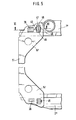
- a water / air cooler for a commercial vehicle which consists of an upper plastic box 1 'made of plastic and a lower plastic box 2' also made of plastic, between them Pipes for guiding the cooling water are arranged in a known manner, of which only the axes 3 are shown, which run perpendicular to the fastening flange 4 'of the water boxes 1' and 2 '.
- the tubes arranged in the direction of the axes 3 are provided with ribs in a known manner and, together with tube sheets (not shown), form a cooler block which is produced by a soldered connection.
- the tube sheets are flanged with the associated flange 4 'of the water tanks 1' and 2 ', as is also known.
- the side parts 5 'and 6' serve to fasten the radiator in the commercial vehicle. These are either made of metal as profile parts or, like the water boxes, are made of a plastic with sufficient stability.
- the side parts 5 'and 6' are formed essentially symmetrically to the central plane 7 of the cooler, but have different fastening projections.
- the side part 5 ' has a laterally projecting support surface 8 ', which is attached to the side part 5' via fastening angles 9 '.
- the surface 8 is used to support part of the frame structure of the vehicle, not shown.
- the side part 6 ' is provided with fastening hooks 10' which protrude from a profiled recess. Both side parts also have features 11 'which are provided with bores for inserting fastening screws. These side parts are very stable. They are provided at the upper and lower ends with fastening tabs 12 'and 13' which laterally overlap the upper water tank 1 'and the lower water tank 2'. These fastening tabs 12 'each consist of two tab parts 12a' and 12b 'or 13a' and 13b 'spanning the water boxes 1' and 2 'on their front and rear sides. They are formed by the arrangement of inclined connecting webs 14 'as corner angles, which serve to reinforce the side parts in these areas.
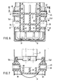
- FIG. 3 and 4 show that the water tank 1 '- and analogously to the water tank 2' - consists of a plastic part provided with longitudinal and transverse ribs 30 and 31 and thereby stably designed in this area, on which 32 from both outer sides outwardly projecting connecting bolts 33 are provided in the form of hollow connecting pieces, which are formed in one piece from the material of the water box 1 'and, in the exemplary embodiment, are cast or injection-molded from the plastic material.
- These connecting bolts 33 also have circumferential grooves 34 in the region of their free end, into which - similarly to the main patent - the spring clips 35 shown in FIG. 4 are inserted in a snap-in manner.
- a further connecting bolt 36 in the form of a fitting pin which, as can also be seen in particular from FIG. 1, a shorter one is also integrally formed on the water box 1 ' Has a distance from the end faces of the water boxes 1 'or 2' provided with the side parts 5 'or 6'.
- This connecting pin 36 is provided with a run-up slope 37, which rises from the end faces, that is to say from the assigned side part 5 'or 6', and rises to the longitudinal center plane 7 of the radiator and, for manufacturing reasons, is also designed as a short hollow pin which, however, in contrast to the connecting pin 33, not round in cross section, but rectangular.
- This connecting pin 36 also does not protrude outward as far from the sides 32 as the connecting pin 33.
- FIG. 1 shows that the fastening tabs 12 'and 13' in the region of the fastening bolts 35 and 36 are not held together by the outer end wall 41, but rather project freely parallel to one another. They therefore spread apart when pushed onto the connecting bolt 36 until they snap with their openings 38 during the further pushing-on process over these bolts 36, the opening 42 associated with the connecting bolt 33, in the exemplary embodiment according to FIGS snap free sides of the connecting bolts 33 into the position shown in FIG. 3. It is then sufficient to slide on spring clips 35 so that the side parts 5 ' or 6 'are secured to the water boxes 1' and 2 '.
- a fixed bearing is provided in the area of the fastening tabs 13 ', i.e. on the underside of the side parts 5' and 6 '.
- the dimensions of the openings 38 and 42 in the fastening tabs 12 'and 13' correspond to the outer dimensions of the fastening bolts 33 and 36.
- this is also the case transversely to the longitudinal center plane 7.
- a so-called floating bearing is formed between the side parts 5 'and 6' and the upper water tank 1 ', as was the case with the subject of the main patent.
- FIGS. 5 to 7 corresponds to that of FIGS. 1 to 4, but with the difference that here the securing of the tab parts 12a 'and 12b' of the side parts 5 'and 6' is not carried out by a spring clip 35, but by a resilient locking device on the interior corresponding to the connecting pin 33, that is, towards the longitudinal center plane 7 facing connecting pin.
- the remaining design corresponds to that of the embodiment of FIGS. 1 to 4.
- the same reference numerals are therefore chosen for the corresponding parts.
- the connecting pin 45 of the embodiment of FIGS. 5 to 7 directed towards the longitudinal center plane 7 has an approximately rectangular outer cross section which is formed from the two outer walls 46 of a double-T middle part 47.
- the two remaining wall parts which complement the overall cross section to form a rectangular cross section, are formed by resilient latching hooks 48, which are provided at their outer ends with hook-shaped lugs 49 which pass through the openings 42 in the tab parts 12a 'and 12b' and fix these after latching hold on the contact surfaces 40 of the ribs 39.
- This embodiment can therefore be assembled without an additional operation in that the side parts 5 ', 6' are pushed laterally onto the water tanks with the tab parts 12a 'and 12b' spreading out on the run-up slope 37 of the connecting bolt 36 and then over the free ends of the connecting bolts 36 and 45, which are fixedly connected to the rattle boxes 1 ', 2' and 2 "and are designed as freely projecting pins snap together with their openings 38 and 42.
- the two latching hooks 48 which lie opposite each other of each connecting bolt 45, are pressed inward until the latching hooks 49 grip over the outer surface of the bracket parts 12a 'and 12b' and thus the fastening tabs firmly on the contact surfaces 40 the ribs 39 hold.
Landscapes
- Engineering & Computer Science (AREA)
- Physics & Mathematics (AREA)
- Thermal Sciences (AREA)
- Mechanical Engineering (AREA)
- General Engineering & Computer Science (AREA)
- Heat-Exchange Devices With Radiators And Conduit Assemblies (AREA)
- Cooling, Air Intake And Gas Exhaust, And Fuel Tank Arrangements In Propulsion Units (AREA)
- Connection Of Plates (AREA)
Applications Claiming Priority (2)
| Application Number | Priority Date | Filing Date | Title |
|---|---|---|---|
| DE19843428857 DE3428857A1 (de) | 1984-08-04 | 1984-08-04 | Wasser/luft-kuehler fuer wassergekuehlte verbrennungskraftmaschinen |
| DE3428857 | 1984-08-04 |
Publications (2)
| Publication Number | Publication Date |
|---|---|
| EP0170952A1 true EP0170952A1 (fr) | 1986-02-12 |
| EP0170952B1 EP0170952B1 (fr) | 1987-11-11 |
Family
ID=6242397
Family Applications (1)
| Application Number | Title | Priority Date | Filing Date |
|---|---|---|---|
| EP85109011A Expired EP0170952B1 (fr) | 1984-08-04 | 1985-07-19 | Radiateur eau/air pour moteur à combustion refroidi à l'eau |
Country Status (5)
| Country | Link |
|---|---|
| US (1) | US4678026A (fr) |
| EP (1) | EP0170952B1 (fr) |
| BR (1) | BR8503656A (fr) |
| DE (2) | DE3428857A1 (fr) |
| ES (1) | ES288069Y (fr) |
Cited By (12)
| Publication number | Priority date | Publication date | Assignee | Title |
|---|---|---|---|---|
| FR2585462A1 (fr) * | 1985-07-27 | 1987-01-30 | Sueddeutsche Kuehler Behr | Echangeur de chaleur, et notamment radiateur ventile pour moteurs a combustion interne |
| FR2602581A1 (fr) * | 1986-08-07 | 1988-02-12 | Valeo | Echangeur de chaleur a faisceau de tubes et boites a fluide en matiere plastique |
| FR2602580A1 (fr) * | 1986-08-07 | 1988-02-12 | Valeo | Echangeur de chaleur a faisceau de tubes et boites a fluide tubulaires |
| DE3705939A1 (de) * | 1987-02-25 | 1988-09-08 | Sueddeutsche Kuehler Behr | Wasser/luft-kuehler |
| EP0307803A1 (fr) * | 1987-09-15 | 1989-03-22 | Behr GmbH & Co. | Radiateur pour moteur à combustion avec des pièces latérales |
| EP0346602A1 (fr) * | 1988-06-17 | 1989-12-20 | Behr GmbH & Co. | Radiateur de refroidissement air/eau pour moteurs à explosion à refroidissement par eau, spécialement pour véhicules utilitaires |
| EP0502836A2 (fr) * | 1991-03-06 | 1992-09-09 | Valeo Engine Cooling Aktiebolag | Radiateur pour moteur à combustion interne |
| FR2697907A1 (fr) * | 1992-11-09 | 1994-05-13 | Valeo Thermique Moteur Sa | Echangeur de chaleur à boîtes à eau reliées par des montants, notamment pour véhicule automobile. |
| DE4243204A1 (de) * | 1992-12-19 | 1994-06-23 | Behr Gmbh & Co | Wasser-Luft-Kühler für wassergekühlte Verbrennungskraftmaschinen |
| DE19722098A1 (de) * | 1997-03-11 | 1998-09-17 | Behr Gmbh & Co | Wärmeübertrager für ein Kraftfahrzeug |
| US6293334B1 (en) | 1997-03-11 | 2001-09-25 | Behr Gmbh & Co. | Heat transfer assembly for a motor vehicle and method of assembling same |
| CN111022175A (zh) * | 2019-11-29 | 2020-04-17 | 全椒赛德利机械有限公司 | 一种自动清洗式柴油发动机散热器 |
Families Citing this family (23)
| Publication number | Priority date | Publication date | Assignee | Title |
|---|---|---|---|---|
| US4940086A (en) * | 1987-04-16 | 1990-07-10 | Modine Manufacturing Company | Tank for a heat exchanger |
| US5127466A (en) * | 1989-10-06 | 1992-07-07 | Sanden Corporation | Heat exchanger with header bracket and insertable header plate |
| CA2006002C (fr) * | 1989-12-19 | 1993-07-20 | Blake J. Grundy | Faisceau de radiateur et methode d'assemblage |
| DE9002438U1 (fr) * | 1990-03-02 | 1990-04-12 | Sueddeutsche Kuehlerfabrik Julius Fr. Behr Gmbh & Co Kg, 7000 Stuttgart, De | |
| FR2674014B1 (fr) * | 1991-03-12 | 1993-05-28 | Valeo Thermique Moteur Sa | Echangeur de chaleur a boites a eau reliees pour vehicules automobiles. |
| DE4109284A1 (de) * | 1991-03-21 | 1992-09-24 | Behr Gmbh & Co | Wasser/luft-kuehler fuer wassergekuehlte verbrennungskraftmaschinen |
| JP2546505Y2 (ja) * | 1991-05-23 | 1997-09-03 | 株式会社ゼクセル | 熱交換器のブラケット取付構造 |
| US5257662A (en) * | 1992-03-27 | 1993-11-02 | The Allen Group Inc. | Heat exchanger assembly |
| DE4222837C2 (de) * | 1992-07-11 | 2003-12-04 | Behr Gmbh & Co | Anordnung eines Kondensators in einem Fahrzeug |
| JPH0622018U (ja) * | 1992-08-27 | 1994-03-22 | サンデン株式会社 | 熱交換器のブラケット構造 |
| DE4425350A1 (de) * | 1994-07-18 | 1996-01-25 | Behr Gmbh & Co | Anordnung zur Verbindung von zwei oder mehr Wärmetauschern |
| FR2739598B1 (fr) * | 1995-10-06 | 1997-12-05 | Valeo Thermique Moteur Sa | Dispositif de fixation d'un echangeur de chaleur fonctionnant a temperature elevee |
| US5566748A (en) * | 1995-11-13 | 1996-10-22 | Alliedsignal Inc. | Charge air cooler/condenser sub-assembly for use in a motor vehicle |
| WO1997024562A1 (fr) * | 1995-12-28 | 1997-07-10 | H-Tech, Inc. | Element chauffant pour fluides |
| US6446711B1 (en) | 2000-12-27 | 2002-09-10 | Modine Manufacturing Company | Side piece for heat exchangers |
| US6543404B2 (en) * | 2001-04-04 | 2003-04-08 | Dow Global Technologies, Inc. | Adhesively bonded engine intake manifold assembly |
| DE10316755A1 (de) * | 2003-04-10 | 2004-10-28 | Behr Gmbh & Co. Kg | Sammelkasten und Wärmeübertrager |
| DE10316754A1 (de) * | 2003-04-10 | 2004-10-28 | Behr Gmbh & Co. Kg | Sammelkasten, Wärmeübertrager und Verfahren zur Herstellung eines Sammelkastens |
| US7360519B2 (en) * | 2003-07-10 | 2008-04-22 | Dow Global Technologies, Inc. | Engine intake manifold assembly |
| US7290594B2 (en) * | 2004-06-15 | 2007-11-06 | Sun Chan | Intercooler |
| US7775265B2 (en) * | 2004-09-15 | 2010-08-17 | Flex-A-Lite Consolidated, Inc. | Side tank design |
| US7694724B2 (en) * | 2005-03-24 | 2010-04-13 | Centrum Equities Acquisition, Llc | Engine cooling radiator |
| DE102007008536A1 (de) * | 2007-02-21 | 2008-08-28 | Modine Manufacturing Co., Racine | Wärmetauscher |
Citations (2)
| Publication number | Priority date | Publication date | Assignee | Title |
|---|---|---|---|---|
| FR2494828A1 (fr) * | 1980-11-24 | 1982-05-28 | Chausson Usines Sa | Echangeur de chaleur assemble mecaniquement du type a tubes et ailettes |
| DE3303986A1 (de) * | 1983-02-05 | 1984-08-09 | Süddeutsche Kühlerfabrik Julius Fr. Behr GmbH & Co KG, 7000 Stuttgart | Wasser/luft-kuehler fuer wassergekuehlte verbrennungskraftmaschinen, insbesondere von nutzfahrzeugen |
Family Cites Families (11)
| Publication number | Priority date | Publication date | Assignee | Title |
|---|---|---|---|---|
| US1347219A (en) * | 1917-06-13 | 1920-07-20 | Edward R Greenlaw | Sectional radiator |
| US1516695A (en) * | 1924-07-07 | 1924-11-25 | Atkinson Sydney | Sectional motor radiator |
| US2056318A (en) * | 1935-06-07 | 1936-10-06 | Ira C Kilbourn | Radiator and mounting |
| US2205984A (en) * | 1938-02-10 | 1940-06-25 | Bush Mfg Company | Radiator |
| US2506051A (en) * | 1947-09-12 | 1950-05-02 | Young Radiator Co | Radiator core mounting |
| FR2239659B1 (fr) * | 1973-08-01 | 1976-05-07 | Chausson Usines Sa | |
| FR2259344A1 (en) * | 1974-01-24 | 1975-08-22 | Chausson Usines Sa | Water collector tank on heat exchanger - bottom rim held inside flanged skirt by clips punched from skirt |
| FR2444580A1 (fr) * | 1978-12-22 | 1980-07-18 | Ferodo Sa | Dispositif de montage d'un echangeur de chaleur dans un carter d'appareil de chauffage, de ventilation et/ou de climatisation, notamment d'un habitacle de vehicule automobile et echangeur equipe d'un tel dispositif |
| US4382464A (en) * | 1981-08-12 | 1983-05-10 | Ex-Cell-O Corporation | Radiator |
| FR2522401B1 (fr) * | 1982-02-26 | 1987-06-19 | Valeo | Echangeur de chaleur, en particulier radiateur d'un circuit de refroidissement de moteur d'un vehicule |
| EP0102715A3 (fr) * | 1982-09-03 | 1984-08-01 | Unipart Group Limited | Echangeurs de chaleur |
-
1984
- 1984-08-04 DE DE19843428857 patent/DE3428857A1/de not_active Ceased
-
1985
- 1985-07-15 ES ES1985288069U patent/ES288069Y/es not_active Expired
- 1985-07-19 EP EP85109011A patent/EP0170952B1/fr not_active Expired
- 1985-07-19 DE DE8585109011T patent/DE3560964D1/de not_active Expired
- 1985-08-02 BR BR8503656A patent/BR8503656A/pt not_active IP Right Cessation
- 1985-08-05 US US06/762,286 patent/US4678026A/en not_active Expired - Fee Related
Patent Citations (2)
| Publication number | Priority date | Publication date | Assignee | Title |
|---|---|---|---|---|
| FR2494828A1 (fr) * | 1980-11-24 | 1982-05-28 | Chausson Usines Sa | Echangeur de chaleur assemble mecaniquement du type a tubes et ailettes |
| DE3303986A1 (de) * | 1983-02-05 | 1984-08-09 | Süddeutsche Kühlerfabrik Julius Fr. Behr GmbH & Co KG, 7000 Stuttgart | Wasser/luft-kuehler fuer wassergekuehlte verbrennungskraftmaschinen, insbesondere von nutzfahrzeugen |
Cited By (17)
| Publication number | Priority date | Publication date | Assignee | Title |
|---|---|---|---|---|
| FR2585462A1 (fr) * | 1985-07-27 | 1987-01-30 | Sueddeutsche Kuehler Behr | Echangeur de chaleur, et notamment radiateur ventile pour moteurs a combustion interne |
| FR2602581A1 (fr) * | 1986-08-07 | 1988-02-12 | Valeo | Echangeur de chaleur a faisceau de tubes et boites a fluide en matiere plastique |
| FR2602580A1 (fr) * | 1986-08-07 | 1988-02-12 | Valeo | Echangeur de chaleur a faisceau de tubes et boites a fluide tubulaires |
| EP0256913A1 (fr) * | 1986-08-07 | 1988-02-24 | Valeo Thermique Moteur | Echangeur de chaleur à faisceau de tubes et boîtes à fluides en matière plastique |
| DE3705939A1 (de) * | 1987-02-25 | 1988-09-08 | Sueddeutsche Kuehler Behr | Wasser/luft-kuehler |
| EP0307803A1 (fr) * | 1987-09-15 | 1989-03-22 | Behr GmbH & Co. | Radiateur pour moteur à combustion avec des pièces latérales |
| EP0346602A1 (fr) * | 1988-06-17 | 1989-12-20 | Behr GmbH & Co. | Radiateur de refroidissement air/eau pour moteurs à explosion à refroidissement par eau, spécialement pour véhicules utilitaires |
| EP0502836A2 (fr) * | 1991-03-06 | 1992-09-09 | Valeo Engine Cooling Aktiebolag | Radiateur pour moteur à combustion interne |
| EP0502836A3 (en) * | 1991-03-06 | 1993-02-24 | Blackstone Sweden Ab | Radiator for an internal combustion engine |
| FR2697907A1 (fr) * | 1992-11-09 | 1994-05-13 | Valeo Thermique Moteur Sa | Echangeur de chaleur à boîtes à eau reliées par des montants, notamment pour véhicule automobile. |
| EP0597767A1 (fr) * | 1992-11-09 | 1994-05-18 | Valeo Thermique Moteur | Echangeur de chaleur à boîtes à eau reliées par des montants notamment pour véhicule automobile |
| DE4243204A1 (de) * | 1992-12-19 | 1994-06-23 | Behr Gmbh & Co | Wasser-Luft-Kühler für wassergekühlte Verbrennungskraftmaschinen |
| FR2699597A1 (fr) * | 1992-12-19 | 1994-06-24 | Behr Gmbh & Co | Radiateur à eau refroidi à l'air pour moteur à combustion interne. |
| DE19722098A1 (de) * | 1997-03-11 | 1998-09-17 | Behr Gmbh & Co | Wärmeübertrager für ein Kraftfahrzeug |
| US6293334B1 (en) | 1997-03-11 | 2001-09-25 | Behr Gmbh & Co. | Heat transfer assembly for a motor vehicle and method of assembling same |
| DE19722098B4 (de) * | 1997-03-11 | 2007-01-18 | Behr Gmbh & Co. Kg | Wärmeübertrager für ein Kraftfahrzeug |
| CN111022175A (zh) * | 2019-11-29 | 2020-04-17 | 全椒赛德利机械有限公司 | 一种自动清洗式柴油发动机散热器 |
Also Published As
| Publication number | Publication date |
|---|---|
| ES288069Y (es) | 1986-06-16 |
| BR8503656A (pt) | 1986-05-06 |
| US4678026A (en) | 1987-07-07 |
| DE3560964D1 (en) | 1987-12-17 |
| DE3428857A1 (de) | 1986-02-13 |
| ES288069U (es) | 1985-11-16 |
| EP0170952B1 (fr) | 1987-11-11 |
Similar Documents
| Publication | Publication Date | Title |
|---|---|---|
| EP0170952B1 (fr) | Radiateur eau/air pour moteur à combustion refroidi à l'eau | |
| DE3001414C2 (de) | Verbindungsanordnung | |
| DE2449045C3 (de) | Anordnung zur Verbindung der Rohrplatten, der Seitenteile und des Wasserkastens eines Wärmetauschers | |
| DE8120936U1 (de) | Rohrfensterheber, insbesondere fuer kraftfahrzeugfenster | |
| DE19941499B4 (de) | Verbindungsstück zum Verbinden eines Wischblatts mit einem Wischerarm | |
| DE3430121A1 (de) | Instrumententafel fuer kraftfahrzeuge | |
| EP0219021A2 (fr) | Echangeur de chaleur, en particulier refroidisseur pour véhicules automobiles | |
| DE19603957A1 (de) | Aggregateträger für ein Kraftfahrzeug | |
| DE4244037A1 (de) | Kühlaggregat für einen Verbrennungsmotor | |
| DE3328998C2 (de) | Befestigungsanordnung für ein Wischerblatt und dabei verwendbarer Verriegelungseinsatz | |
| EP0504635B1 (fr) | Radiateur eau/air pour moteurs à combustion interne refroidis par eau | |
| DE3902399A1 (de) | Zierleistenhalter | |
| DE102010004686A1 (de) | Rastverbindungsmittel für eine Baugruppe | |
| EP0280107B1 (fr) | Refroidisseur eau-air | |
| DE3009704A1 (de) | Vorrichtung zur gelenkigen halterung eines scheibenwischer-wischblattes an einem wischarm | |
| DE19923487B4 (de) | Widerlager mit Formteil zum Befestigen von Betätigungszügen | |
| DE3214453A1 (de) | Waermetauscher, insbesondere kuehler fuer kraftfahrzeuge | |
| EP0346602A1 (fr) | Radiateur de refroidissement air/eau pour moteurs à explosion à refroidissement par eau, spécialement pour véhicules utilitaires | |
| DE3907926A1 (de) | Waermetauscher, insbesondere kuehler fuer nutzfahrzeuge | |
| EP0593909A1 (fr) | Clip d'ancrage en plastique pour enjoliveurs, protecteurs ou similaires, en particulier pour voitures | |
| DE3340449A1 (de) | Scheibenwischer, insbesondere fuer kraftfahrzeuge | |
| DE102011011253A1 (de) | Lufteinlass zur Belüftung der Fahrgastzelle eines Kraftfahrzeuges | |
| DE2922543A1 (de) | Stuetzklammer | |
| DE4122898A1 (de) | Befestigungsanordnung | |
| DE3425646C1 (de) | Scheinwerfer, insbesondere für Kraftfahrzeuge |
Legal Events
| Date | Code | Title | Description |
|---|---|---|---|
| PUAI | Public reference made under article 153(3) epc to a published international application that has entered the european phase |
Free format text: ORIGINAL CODE: 0009012 |
|
| AK | Designated contracting states |
Designated state(s): DE FR GB IT NL SE |
|
| 17P | Request for examination filed |
Effective date: 19860318 |
|
| 17Q | First examination report despatched |
Effective date: 19860714 |
|
| GRAA | (expected) grant |
Free format text: ORIGINAL CODE: 0009210 |
|
| AK | Designated contracting states |
Kind code of ref document: B1 Designated state(s): DE FR GB IT NL SE |
|
| ITF | It: translation for a ep patent filed |
Owner name: JACOBACCI & PERANI S.P.A. |
|
| GBT | Gb: translation of ep patent filed (gb section 77(6)(a)/1977) | ||
| REF | Corresponds to: |
Ref document number: 3560964 Country of ref document: DE Date of ref document: 19871217 |
|
| ET | Fr: translation filed | ||
| PLBI | Opposition filed |
Free format text: ORIGINAL CODE: 0009260 |
|
| 26 | Opposition filed |
Opponent name: KUEHLERFABRIK LAENGERER & REICH GMBH & CO. KG Effective date: 19880707 |
|
| NLR1 | Nl: opposition has been filed with the epo |
Opponent name: KUEHLERFABRIK LAENGERER & REICH GMBH & CO. KG |
|
| RAP2 | Party data changed (patent owner data changed or rights of a patent transferred) |
Owner name: BEHR GMBH & CO. |
|
| NLT2 | Nl: modifications (of names), taken from the european patent patent bulletin |
Owner name: BEHR GMBH & CO. TE STUTTGART, BONDSREPUBLIEK DUITS |
|
| PGFP | Annual fee paid to national office [announced via postgrant information from national office to epo] |
Ref country code: SE Payment date: 19910610 Year of fee payment: 7 |
|
| PGFP | Annual fee paid to national office [announced via postgrant information from national office to epo] |
Ref country code: GB Payment date: 19910625 Year of fee payment: 7 |
|
| PGFP | Annual fee paid to national office [announced via postgrant information from national office to epo] |
Ref country code: FR Payment date: 19910626 Year of fee payment: 7 |
|
| ITTA | It: last paid annual fee | ||
| PGFP | Annual fee paid to national office [announced via postgrant information from national office to epo] |
Ref country code: NL Payment date: 19910731 Year of fee payment: 7 Ref country code: DE Payment date: 19910731 Year of fee payment: 7 |
|
| RDAG | Patent revoked |
Free format text: ORIGINAL CODE: 0009271 |
|
| STAA | Information on the status of an ep patent application or granted ep patent |
Free format text: STATUS: PATENT REVOKED |
|
| 27W | Patent revoked |
Effective date: 19920218 |
|
| GBPR | Gb: patent revoked under art. 102 of the ep convention designating the uk as contracting state | ||
| NLR2 | Nl: decision of opposition | ||
| EUG | Se: european patent has lapsed |
Ref document number: 85109011.8 Effective date: 19920415 |
|
| APAH | Appeal reference modified |
Free format text: ORIGINAL CODE: EPIDOSCREFNO |