EP0166645B1 - Biegsame Achse zur beweglichen Verbindung von hakenartigen Transportriemenschlössern - Google Patents
Biegsame Achse zur beweglichen Verbindung von hakenartigen Transportriemenschlössern Download PDFInfo
- Publication number
- EP0166645B1 EP0166645B1 EP85401112A EP85401112A EP0166645B1 EP 0166645 B1 EP0166645 B1 EP 0166645B1 EP 85401112 A EP85401112 A EP 85401112A EP 85401112 A EP85401112 A EP 85401112A EP 0166645 B1 EP0166645 B1 EP 0166645B1
- Authority
- EP
- European Patent Office
- Prior art keywords
- sheath
- flexible
- axis
- plastic material
- pin
- Prior art date
- Legal status (The legal status is an assumption and is not a legal conclusion. Google has not performed a legal analysis and makes no representation as to the accuracy of the status listed.)
- Expired
Links
Images

Classifications
-
- F—MECHANICAL ENGINEERING; LIGHTING; HEATING; WEAPONS; BLASTING
- F16—ENGINEERING ELEMENTS AND UNITS; GENERAL MEASURES FOR PRODUCING AND MAINTAINING EFFECTIVE FUNCTIONING OF MACHINES OR INSTALLATIONS; THERMAL INSULATION IN GENERAL
- F16G—BELTS, CABLES, OR ROPES, PREDOMINANTLY USED FOR DRIVING PURPOSES; CHAINS; FITTINGS PREDOMINANTLY USED THEREFOR
- F16G3/00—Belt fastenings, e.g. for conveyor belts
- F16G3/02—Belt fastenings, e.g. for conveyor belts with series of eyes or the like, interposed and linked by a pin to form a hinge
-
- Y—GENERAL TAGGING OF NEW TECHNOLOGICAL DEVELOPMENTS; GENERAL TAGGING OF CROSS-SECTIONAL TECHNOLOGIES SPANNING OVER SEVERAL SECTIONS OF THE IPC; TECHNICAL SUBJECTS COVERED BY FORMER USPC CROSS-REFERENCE ART COLLECTIONS [XRACs] AND DIGESTS
- Y10—TECHNICAL SUBJECTS COVERED BY FORMER USPC
- Y10T—TECHNICAL SUBJECTS COVERED BY FORMER US CLASSIFICATION
- Y10T24/00—Buckles, buttons, clasps, etc.
- Y10T24/16—Belt fasteners
- Y10T24/1608—Hinged
- Y10T24/162—Pintle pin connected belt ends
Definitions
- the present invention relates to the junction of conveyor belts by means of two rows of metal staples, joined by a hinge pin.
- the staples used for this purpose consist of U-shaped elements, capable of being arranged astride the corresponding end of a conveyor belt to be fixed by means of metal cleats or any other suitable members. These staples have knuckles projecting from the edge of the corresponding end of the mat and the arrangement is such that the knuckles of two complementary rows can be nested to be joined by engagement of a junction pin inside of the passage formed by these knuckles.
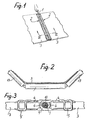
- This axis therefore allows the articulation of the two corresponding rows of staples when the belt passes over a drive or return drum.
- this axis can flex in the transverse direction so that the belt can take on the shape of a trough on the rollers of a conveyor, when it is in service. This is the reason why axes of this kind are generally constituted by a cable twisted in metal wires.
- patent FR-A-2 118 395 describes a junction pin comprising a central core formed by a metal strand around which several other metal strands are twisted, the whole being enclosed in an external plastic sheath which is extruded thereon.
- an axis does not have sufficient resistance to wear due to the very fact that its external surface consists of the plastic sheath.
- the present invention aims to achieve a junction pin designed so as to allow good articulation of the knuckles of the staples and nevertheless to have satisfactory flexibility, while having very good resistance to wear.
- the invention relates to a flexible axis for the joining and articulation of two complementary rows of staples for joining a conveyor belt or the like, comprising a flexible central core, which may be constituted by a metal cable. or the like and a flexible plastic sheath enveloping this core, and characterized in that there is further provided an outer casing of tubular shape, formed by the twisting of one or more monotorons of steel wire or other suitable metal , so that the plastic sheath occupies an intermediate position between the central core and this external envelope and can thus play the role of an intermediate element allowing the sliding of one of these elements relative to the other, the twisting of the outer casing can be in the same direction or in the opposite direction to the direction of the twisting of the inner core.
- this axis the mechanical strength of the internal core of this axis is reinforced by the external envelope provided around it.
- this envelope does not oppose the flexibility of the axis.
- the interposition of the intermediate plastic sheath has the essential advantage that there is no risk of seizure between the two elements in question, which seizure would constitute an obstacle to normal sliding and could cause premature wear of these elements.
- the intermediate sheath of this axis is made of a plastic material loaded with grease, or hard grease, capable of creeping under the effect of relative movements occurring between the various constituent elements of this axis, during bending of it, so that a fraction of this fat spreads on the surface of this axis.
- the lubrication thus obtained has the advantage of avoiding any risk of seizing the knuckles of the connecting clips on the present axis. In addition, this lubrication allows good articulation of these knuckles without premature wear of the junction pin.
- the intermediate sheath 9 is produced by extrusion directly around the central cable 7, the external envelope 10 being for its part then twisted on this sheath, so that the steel wires 11 of this envelope are printed on the external surface of this sheath by forming helical grooves 12.
- the plastic material used for the production of the intermediate sheath 9 by extrusion can be for example polyethylene.
- this axis has the flexibility required to allow the conveyor belt 3 to curve in the shape of a trough on the guide rollers 13 of a conveyor, as shown in FIG. 2.
- this axis has a very high mechanical resistance allowing it to transmit the desired tensile forces between one end and the other of a conveyor belt.
- the presence of the outer sheath 10 is not an obstacle to the flexibility of the present act, - quite the contrary -.
- the realization of this axis in the form of two distinct metallic elements - namely: the internal core and the external envelope - promotes its flexibility in the transverse direction, because these elements can slide one on the other during their bending.
- the interposition of the intermediate sheath 9 in plastic material promotes this sliding while avoiding any risk of seizure between the two elements in question, with the drawbacks which would have resulted therefrom: reduction in the flexibility of the axis and risk of premature wear of its constituent elements.
- the diagram in FIG. 6 illustrates the slip which can occur in such a case for a specific strand 11 of the external envelope 10, which strand can successively occupy positions 11 b and 11 c, due to its difference in bending relative to bending of the inner core 7.
- the intermediate sheath 9 is made of a plastic material, for example polyethylene, loaded with a grease capable of migrating outside under the effect of the deformations imposed subsequently on this sheath.
- This grease may be a grease based on silicone or on molybdenum bisufure.
- the axis according to the invention is able to provide lubrication of its contact surface with the knuckles 6 of the staples. Indeed, the stresses and deformations imposed on the intermediate sheath 9, during various flexions of the axis, cause the migration of the fat contained inside this sheath 10. Under these conditions this fat is caused to flow between the monotorons 11 of the outer casing 10. This therefore causes it to lubricate the outer surface of this casing.
- a very small amount of grease is sufficient to provide the desired lubrication, so that a flexible shaft according to the invention is capable of ensuring good lubrication for a long time.
- Such lubrication therefore makes it possible to avoid the risks of seizing of the knuckles 6 of the junction staples.
- This lubrication also has the advantage of facilitating the articulation of the knuckles 6, thereby avoiding too rapid wear of their junction axis.
- FIG. 5 represents another embodiment in which the structure of the corresponding flexible axis differs from the previous one only by the fact that instead of being constituted by a cable 7, the central core consists of a metal spring 14.
- the central core consists of a metal spring 14.
- the other cost-effective elements of this axis 1a they are identical to those provided previously since they consist of an outer casing 10a identical to the casing 10, and an intermediate sheath 9a made of plastic, identical to the sheath 9 in Figure 4.
- the plastic material constituting this sheath is also charged with a grease capable of migrating to the outside.
- the direction of twisting of this spring is opposite to the direction of twist of the monotorons 11 of the outer casing 10 of the corresponding cable.
- the inversion of these two directions of twisting is one of the conditions for obtaining that the deformations undergone by the internal core and by the external envelope exert, on the intermediate lining 9 or 9a, constraints of an appropriate nature to cause the migration of the fat contained therein.
- the internal core of the cable according to FIG. 5 is constituted by a metal spring, the same result is therefore obtained as with the embodiment of FIG. 4.
- the monotorons of the outer envelope 7 or 7a of each of the embodiments described above may have a section other than circular, for example a section of shape such that the surface of this envelope is approximately smooth, so as to produce an excellent bearing surface for the knuckles 6 of the junction staples.
- the flexible junction axis according to the invention is not limited to the two embodiments shown sensed in FIGS. 4 and 5, these having been described simply by way of indicative example.
Landscapes
- Engineering & Computer Science (AREA)
- General Engineering & Computer Science (AREA)
- Mechanical Engineering (AREA)
- Ropes Or Cables (AREA)
- Belt Conveyors (AREA)
- Chain Conveyers (AREA)
Claims (3)
Applications Claiming Priority (2)
| Application Number | Priority Date | Filing Date | Title |
|---|---|---|---|
| FR8410026 | 1984-06-26 | ||
| FR8410026A FR2566477B1 (fr) | 1984-06-26 | 1984-06-26 | Axe flexible pour la reunion et l'articulation des agrafes de jonction d'un tapis transporteur |
Publications (2)
| Publication Number | Publication Date |
|---|---|
| EP0166645A1 EP0166645A1 (de) | 1986-01-02 |
| EP0166645B1 true EP0166645B1 (de) | 1988-05-11 |
Family
ID=9305429
Family Applications (1)
| Application Number | Title | Priority Date | Filing Date |
|---|---|---|---|
| EP85401112A Expired EP0166645B1 (de) | 1984-06-26 | 1985-06-06 | Biegsame Achse zur beweglichen Verbindung von hakenartigen Transportriemenschlössern |
Country Status (8)
| Country | Link |
|---|---|
| US (1) | US4671403A (de) |
| EP (1) | EP0166645B1 (de) |
| JP (1) | JPS6112504A (de) |
| AU (1) | AU4348385A (de) |
| CA (1) | CA1231913A (de) |
| DE (1) | DE3562658D1 (de) |
| FR (1) | FR2566477B1 (de) |
| ZA (1) | ZA854405B (de) |
Families Citing this family (27)
| Publication number | Priority date | Publication date | Assignee | Title |
|---|---|---|---|---|
| US5049425A (en) * | 1989-01-04 | 1991-09-17 | Abany International Corporation | Porous yarn for OMS pintles |
| EP0437639B1 (de) * | 1989-12-14 | 1993-11-10 | Goro S.A. | Dichtung für die Verbindung von zwei Stücken eines Förderbandes und eine solche Dichtung aufweisende Verbindung |
| FR2664009B1 (fr) * | 1990-06-27 | 1995-07-13 | Goro Sa | Agrafes pour la jonction des extremites d'un tapis transporteur et appareil pour la fixation de telles agrafes. |
| DE9016586U1 (de) * | 1990-12-06 | 1991-02-21 | Mühlen Sohn GmbH & Co., 7906 Blaustein | Gurtverbindung für Fördergurte o.dgl. |
| DE4110818C1 (de) * | 1991-04-04 | 1992-09-17 | Mato Maschinen- Und Metallwarenfabrik Curt Matthaei Gmbh & Co Kg, 6050 Offenbach, De | |
| FR2701300B1 (fr) * | 1993-02-09 | 1995-03-31 | Aser Sarl | Dispositif de jonctionnement pour bande transporteuse. |
| DE4318836A1 (de) * | 1993-06-07 | 1994-12-08 | Mato Masch & Metallwaren | Verbindungselement für Förderbänder |
| FR2706964B1 (de) * | 1993-06-21 | 1995-09-01 | Aser Sarl | |
| AU685200B2 (en) * | 1994-02-02 | 1998-01-15 | Mato Maschinen- Und Metallwarenfabrik Curt Matthaei Gmbh & Co Kg | Coupling bar |
| IN188123B (de) * | 1995-04-20 | 2002-08-24 | Vi Goro Sarl | |
| DE19531432A1 (de) * | 1995-08-27 | 1997-03-06 | Mato Masch & Metallwaren | Förderband zur Verwendung in einer Fördervorrichtung mit einer Muldungszone |
| US5620085A (en) * | 1996-02-02 | 1997-04-15 | General Signal Corporation | Spliced conveyer belt assembly |
| US5896981A (en) * | 1997-01-03 | 1999-04-27 | General Signal Corporation | Spliced conveyer belt method and apparatus |
| DE19702005A1 (de) * | 1997-01-22 | 1998-07-23 | Goro Sa | Kupplungsstab |
| DE19820717A1 (de) * | 1998-05-11 | 1999-11-18 | Mato Masch & Metallwaren | Verbindung zweier Enden eines Förderbandes |
| FR2792050B1 (fr) * | 1999-04-12 | 2001-06-08 | Aser Sarl | Agrafe a griffes pour jonctions de bandes transporteuses |
| AU2001288462A1 (en) * | 2000-08-30 | 2002-03-13 | Cerebral Vascular Applications Inc. | Medical instrument |
| US6755338B2 (en) * | 2001-08-29 | 2004-06-29 | Cerebral Vascular Applications, Inc. | Medical instrument |
| US6687961B2 (en) * | 2002-02-20 | 2004-02-10 | Tuthill Controls Group | Hinge pin connector |
| WO2003076824A2 (en) * | 2002-03-04 | 2003-09-18 | Flexible Steel Lacing Company | Conveyor belt fasteners |
| EP2423535A3 (de) * | 2010-08-23 | 2012-05-09 | Innova Patent GmbH | Fördergurt für eine Bandförderanlage |
| CN104444067A (zh) * | 2013-09-16 | 2015-03-25 | 无锡百科知识产权有限公司 | 一种皮带运输线的连接方法 |
| USD808253S1 (en) | 2014-08-18 | 2018-01-23 | Flexible Steel Lacing Company | Fastener for a conveyor belt |
| CA3242235A1 (en) | 2014-08-18 | 2016-02-25 | Flexible Steel Lacing Company | Conveyor belt fastener and method of manufacture |
| DE102015212748A1 (de) * | 2015-07-08 | 2017-01-12 | Contitech Transportbandsysteme Gmbh | Gurt oder Gurtsegment |
| DE102015214395A1 (de) * | 2015-07-29 | 2017-02-02 | Contitech Transportbandsysteme Gmbh | Gurt oder Gurtsegment |
| WO2023147079A1 (en) | 2022-01-28 | 2023-08-03 | Flexible Steel Lacing Company | Conveyor belt fastener |
Family Cites Families (11)
| Publication number | Priority date | Publication date | Assignee | Title |
|---|---|---|---|---|
| US2370884A (en) * | 1943-08-05 | 1945-03-06 | Smith Joseph Leigh | Flexible shaft |
| DE1234459B (de) * | 1963-06-01 | 1967-02-16 | Scapa Dryers Ltd | Verbindungsbolzen fuer eine scharnierartige Riemenverbindung fuer Riemen und andere flache Gewebe fuer gewerbliche Zwecke, insbesondere fuer Papiermaschinen-Trockenfilze |
| US3319217A (en) * | 1966-02-25 | 1967-05-09 | New Twist Connector Corp | Spirally wound pin connector |
| US4007303A (en) * | 1970-10-30 | 1977-02-08 | Fitztuchverwaltungs-Gesellschaft Mit Beschrankter Haftung | Method of making pintle wire for high load hinge connections |
| FR2118395A5 (de) * | 1970-12-17 | 1972-07-28 | Minet | |
| DE2240013C3 (de) * | 1972-08-14 | 1982-01-14 | Mato Maschinen- Und Metallwarenfabrik Curt Matthaei Gmbh & Co Kg, 6050 Offenbach | Kupplungsstab |
| DE2449792B1 (de) * | 1974-10-19 | 1976-02-12 | Heimbach Gmbh Thomas Josef | Wendelnaht zum endlosmachen von gewebebaendern |
| DE2507474C2 (de) * | 1975-02-21 | 1983-12-08 | Mato Maschinen- Und Metallwarenfabrik Curt Matthaei Gmbh & Co Kg, 6050 Offenbach | Kupplungsstab zum Verbinden der Enden von Förderbändern |
| US4024605A (en) * | 1975-12-18 | 1977-05-24 | Flexible Steel Lacing Company | Flexible hinge pin |
| DE2920461C2 (de) * | 1979-05-21 | 1981-09-03 | Mato Maschinen- Und Metallwarenfabrik Curt Matthaei Gmbh & Co Kg, 6050 Offenbach | Verbinderstreifen für Fördergurte |
| US4344209A (en) * | 1979-10-22 | 1982-08-17 | Scapa Dryers, Inc. | In-line clipper seam |
-
1984
- 1984-06-26 FR FR8410026A patent/FR2566477B1/fr not_active Expired
-
1985
- 1985-06-06 EP EP85401112A patent/EP0166645B1/de not_active Expired
- 1985-06-06 DE DE8585401112T patent/DE3562658D1/de not_active Expired
- 1985-06-11 ZA ZA854405A patent/ZA854405B/xx unknown
- 1985-06-12 AU AU43483/85A patent/AU4348385A/en not_active Abandoned
- 1985-06-12 US US06/743,893 patent/US4671403A/en not_active Expired - Fee Related
- 1985-06-19 CA CA000484495A patent/CA1231913A/en not_active Expired
- 1985-06-25 JP JP60138842A patent/JPS6112504A/ja active Pending
Also Published As
| Publication number | Publication date |
|---|---|
| EP0166645A1 (de) | 1986-01-02 |
| CA1231913A (en) | 1988-01-26 |
| US4671403A (en) | 1987-06-09 |
| AU4348385A (en) | 1986-01-02 |
| ZA854405B (en) | 1986-02-26 |
| JPS6112504A (ja) | 1986-01-20 |
| FR2566477A1 (fr) | 1985-12-27 |
| FR2566477B1 (fr) | 1987-08-21 |
| DE3562658D1 (en) | 1988-06-16 |
Similar Documents
| Publication | Publication Date | Title |
|---|---|---|
| EP0166645B1 (de) | Biegsame Achse zur beweglichen Verbindung von hakenartigen Transportriemenschlössern | |
| LU84984A1 (fr) | Cables et leur procede de fabrication | |
| FR2473136A1 (fr) | Collier de fixation notamment de cables electriques | |
| FR2713492A1 (fr) | Guide tubulaire orientable, notamment pour un dispositif médico-chirurgical. | |
| LU83406A1 (fr) | Courroie dentee | |
| CA1191915A (fr) | Manchon d'ancrage et de jonction pour conducteur electrique heterogene | |
| FR2566475A1 (fr) | Oreille deformable pour colliers de serrage et collier de serrage la comprenant | |
| EP2596266A2 (de) | Selbsausrichtender sockel für ein schiffstau | |
| EP0187061B1 (de) | Vorrichtung zu einer gelenkigen Verbindung von zwei ergänzenden Reihen von Verbindungshaken | |
| FR2511583A1 (fr) | Bande d'accrochage de fermeture a glissiere etanche | |
| FR2624940A1 (fr) | Axe de jonction pour l'accouplement des extremites d'un tapis transporteur ou similaire | |
| FR2749570A1 (fr) | Cable de transporteur a raclettes pour un transporteur a raclage sous forme de conduit ayant un revetement autour du cable et procede pour sa fabrication | |
| EP0185581A1 (de) | Biegsame rohrförmige Vorrichtung zur Übertragung von Längskräften | |
| FR2633402A1 (fr) | Conducteur optique resistant a la traction | |
| FR2501382A1 (fr) | Element de cable et cable a fibres optiques, notamment susceptible de resister a des tractions et/ou a des pressions elevees et son procede de fabrication | |
| CH345590A (fr) | Bande transporteuse | |
| FR2509398A1 (fr) | Accouplement elastique en rotation | |
| FR2551253A1 (fr) | Cable de transmission, notamment optique, comportant un element elastique | |
| FR2515296A1 (fr) | Courroie trapezoidale a elements de friction rigides rapportes | |
| CH661800A5 (en) | External protective armouring for telecommunication cable | |
| EP0851258A1 (de) | Faseroptisches Kabel, flexibel und mit erhohtem Widerstand | |
| BE897633A (fr) | Cables et leur procede de fabrication | |
| EP4630705A1 (de) | Förderband und verfahren zum schliessen eines förderbandes | |
| FR2488626A1 (fr) | Cable metallique a un seul toron pour armer des produits elastomeres | |
| WO1992009831A1 (fr) | Poulie d'adherence |
Legal Events
| Date | Code | Title | Description |
|---|---|---|---|
| PUAI | Public reference made under article 153(3) epc to a published international application that has entered the european phase |
Free format text: ORIGINAL CODE: 0009012 |
|
| AK | Designated contracting states |
Designated state(s): BE DE FR GB IT |
|
| 17P | Request for examination filed |
Effective date: 19860426 |
|
| 17Q | First examination report despatched |
Effective date: 19870505 |
|
| GRAA | (expected) grant |
Free format text: ORIGINAL CODE: 0009210 |
|
| AK | Designated contracting states |
Kind code of ref document: B1 Designated state(s): BE DE FR GB IT |
|
| PG25 | Lapsed in a contracting state [announced via postgrant information from national office to epo] |
Ref country code: IT Free format text: LAPSE BECAUSE OF FAILURE TO SUBMIT A TRANSLATION OF THE DESCRIPTION OR TO PAY THE FEE WITHIN THE PRESCRIBED TIME-LIMIT;WARNING: LAPSES OF ITALIAN PATENTS WITH EFFECTIVE DATE BEFORE 2007 MAY HAVE OCCURRED AT ANY TIME BEFORE 2007. THE CORRECT EFFECTIVE DATE MAY BE DIFFERENT FROM THE ONE RECORDED. Effective date: 19880511 |
|
| GBT | Gb: translation of ep patent filed (gb section 77(6)(a)/1977) | ||
| REF | Corresponds to: |
Ref document number: 3562658 Country of ref document: DE Date of ref document: 19880616 |
|
| BERE | Be: lapsed |
Owner name: GORO S.A. Effective date: 19880630 |
|
| PLBE | No opposition filed within time limit |
Free format text: ORIGINAL CODE: 0009261 |
|
| STAA | Information on the status of an ep patent application or granted ep patent |
Free format text: STATUS: NO OPPOSITION FILED WITHIN TIME LIMIT |
|
| 26N | No opposition filed | ||
| PG25 | Lapsed in a contracting state [announced via postgrant information from national office to epo] |
Ref country code: BE Effective date: 19890630 |
|
| PGFP | Annual fee paid to national office [announced via postgrant information from national office to epo] |
Ref country code: FR Payment date: 19910627 Year of fee payment: 7 |
|
| PGFP | Annual fee paid to national office [announced via postgrant information from national office to epo] |
Ref country code: DE Payment date: 19910628 Year of fee payment: 7 |
|
| PGFP | Annual fee paid to national office [announced via postgrant information from national office to epo] |
Ref country code: GB Payment date: 19910703 Year of fee payment: 7 |
|
| PG25 | Lapsed in a contracting state [announced via postgrant information from national office to epo] |
Ref country code: GB Effective date: 19920606 |
|
| GBPC | Gb: european patent ceased through non-payment of renewal fee |
Effective date: 19920606 |
|
| PG25 | Lapsed in a contracting state [announced via postgrant information from national office to epo] |
Ref country code: FR Effective date: 19930226 |
|
| PG25 | Lapsed in a contracting state [announced via postgrant information from national office to epo] |
Ref country code: DE Effective date: 19930302 |
|
| REG | Reference to a national code |
Ref country code: FR Ref legal event code: ST |