EP0166645B1 - Flexible axis for articulatedly connecting hooklike locking means of a conveyor belt - Google Patents
Flexible axis for articulatedly connecting hooklike locking means of a conveyor belt Download PDFInfo
- Publication number
- EP0166645B1 EP0166645B1 EP85401112A EP85401112A EP0166645B1 EP 0166645 B1 EP0166645 B1 EP 0166645B1 EP 85401112 A EP85401112 A EP 85401112A EP 85401112 A EP85401112 A EP 85401112A EP 0166645 B1 EP0166645 B1 EP 0166645B1
- Authority
- EP
- European Patent Office
- Prior art keywords
- sheath
- flexible
- axis
- plastic material
- pin
- Prior art date
- Legal status (The legal status is an assumption and is not a legal conclusion. Google has not performed a legal analysis and makes no representation as to the accuracy of the status listed.)
- Expired
Links
Images

Classifications
-
- F—MECHANICAL ENGINEERING; LIGHTING; HEATING; WEAPONS; BLASTING
- F16—ENGINEERING ELEMENTS AND UNITS; GENERAL MEASURES FOR PRODUCING AND MAINTAINING EFFECTIVE FUNCTIONING OF MACHINES OR INSTALLATIONS; THERMAL INSULATION IN GENERAL
- F16G—BELTS, CABLES, OR ROPES, PREDOMINANTLY USED FOR DRIVING PURPOSES; CHAINS; FITTINGS PREDOMINANTLY USED THEREFOR
- F16G3/00—Belt fastenings, e.g. for conveyor belts
- F16G3/02—Belt fastenings, e.g. for conveyor belts with series of eyes or the like, interposed and linked by a pin to form a hinge
-
- Y—GENERAL TAGGING OF NEW TECHNOLOGICAL DEVELOPMENTS; GENERAL TAGGING OF CROSS-SECTIONAL TECHNOLOGIES SPANNING OVER SEVERAL SECTIONS OF THE IPC; TECHNICAL SUBJECTS COVERED BY FORMER USPC CROSS-REFERENCE ART COLLECTIONS [XRACs] AND DIGESTS
- Y10—TECHNICAL SUBJECTS COVERED BY FORMER USPC
- Y10T—TECHNICAL SUBJECTS COVERED BY FORMER US CLASSIFICATION
- Y10T24/00—Buckles, buttons, clasps, etc.
- Y10T24/16—Belt fasteners
- Y10T24/1608—Hinged
- Y10T24/162—Pintle pin connected belt ends
Definitions
- the present invention relates to the junction of conveyor belts by means of two rows of metal staples, joined by a hinge pin.
- the staples used for this purpose consist of U-shaped elements, capable of being arranged astride the corresponding end of a conveyor belt to be fixed by means of metal cleats or any other suitable members. These staples have knuckles projecting from the edge of the corresponding end of the mat and the arrangement is such that the knuckles of two complementary rows can be nested to be joined by engagement of a junction pin inside of the passage formed by these knuckles.
- This axis therefore allows the articulation of the two corresponding rows of staples when the belt passes over a drive or return drum.
- this axis can flex in the transverse direction so that the belt can take on the shape of a trough on the rollers of a conveyor, when it is in service. This is the reason why axes of this kind are generally constituted by a cable twisted in metal wires.
- patent FR-A-2 118 395 describes a junction pin comprising a central core formed by a metal strand around which several other metal strands are twisted, the whole being enclosed in an external plastic sheath which is extruded thereon.
- an axis does not have sufficient resistance to wear due to the very fact that its external surface consists of the plastic sheath.
- the present invention aims to achieve a junction pin designed so as to allow good articulation of the knuckles of the staples and nevertheless to have satisfactory flexibility, while having very good resistance to wear.
- the invention relates to a flexible axis for the joining and articulation of two complementary rows of staples for joining a conveyor belt or the like, comprising a flexible central core, which may be constituted by a metal cable. or the like and a flexible plastic sheath enveloping this core, and characterized in that there is further provided an outer casing of tubular shape, formed by the twisting of one or more monotorons of steel wire or other suitable metal , so that the plastic sheath occupies an intermediate position between the central core and this external envelope and can thus play the role of an intermediate element allowing the sliding of one of these elements relative to the other, the twisting of the outer casing can be in the same direction or in the opposite direction to the direction of the twisting of the inner core.
- this axis the mechanical strength of the internal core of this axis is reinforced by the external envelope provided around it.
- this envelope does not oppose the flexibility of the axis.
- the interposition of the intermediate plastic sheath has the essential advantage that there is no risk of seizure between the two elements in question, which seizure would constitute an obstacle to normal sliding and could cause premature wear of these elements.
- the intermediate sheath of this axis is made of a plastic material loaded with grease, or hard grease, capable of creeping under the effect of relative movements occurring between the various constituent elements of this axis, during bending of it, so that a fraction of this fat spreads on the surface of this axis.
- the lubrication thus obtained has the advantage of avoiding any risk of seizing the knuckles of the connecting clips on the present axis. In addition, this lubrication allows good articulation of these knuckles without premature wear of the junction pin.
- the intermediate sheath 9 is produced by extrusion directly around the central cable 7, the external envelope 10 being for its part then twisted on this sheath, so that the steel wires 11 of this envelope are printed on the external surface of this sheath by forming helical grooves 12.
- the plastic material used for the production of the intermediate sheath 9 by extrusion can be for example polyethylene.
- this axis has the flexibility required to allow the conveyor belt 3 to curve in the shape of a trough on the guide rollers 13 of a conveyor, as shown in FIG. 2.
- this axis has a very high mechanical resistance allowing it to transmit the desired tensile forces between one end and the other of a conveyor belt.
- the presence of the outer sheath 10 is not an obstacle to the flexibility of the present act, - quite the contrary -.
- the realization of this axis in the form of two distinct metallic elements - namely: the internal core and the external envelope - promotes its flexibility in the transverse direction, because these elements can slide one on the other during their bending.
- the interposition of the intermediate sheath 9 in plastic material promotes this sliding while avoiding any risk of seizure between the two elements in question, with the drawbacks which would have resulted therefrom: reduction in the flexibility of the axis and risk of premature wear of its constituent elements.
- the diagram in FIG. 6 illustrates the slip which can occur in such a case for a specific strand 11 of the external envelope 10, which strand can successively occupy positions 11 b and 11 c, due to its difference in bending relative to bending of the inner core 7.
- the intermediate sheath 9 is made of a plastic material, for example polyethylene, loaded with a grease capable of migrating outside under the effect of the deformations imposed subsequently on this sheath.
- This grease may be a grease based on silicone or on molybdenum bisufure.
- the axis according to the invention is able to provide lubrication of its contact surface with the knuckles 6 of the staples. Indeed, the stresses and deformations imposed on the intermediate sheath 9, during various flexions of the axis, cause the migration of the fat contained inside this sheath 10. Under these conditions this fat is caused to flow between the monotorons 11 of the outer casing 10. This therefore causes it to lubricate the outer surface of this casing.
- a very small amount of grease is sufficient to provide the desired lubrication, so that a flexible shaft according to the invention is capable of ensuring good lubrication for a long time.
- Such lubrication therefore makes it possible to avoid the risks of seizing of the knuckles 6 of the junction staples.
- This lubrication also has the advantage of facilitating the articulation of the knuckles 6, thereby avoiding too rapid wear of their junction axis.
- FIG. 5 represents another embodiment in which the structure of the corresponding flexible axis differs from the previous one only by the fact that instead of being constituted by a cable 7, the central core consists of a metal spring 14.
- the central core consists of a metal spring 14.
- the other cost-effective elements of this axis 1a they are identical to those provided previously since they consist of an outer casing 10a identical to the casing 10, and an intermediate sheath 9a made of plastic, identical to the sheath 9 in Figure 4.
- the plastic material constituting this sheath is also charged with a grease capable of migrating to the outside.
- the direction of twisting of this spring is opposite to the direction of twist of the monotorons 11 of the outer casing 10 of the corresponding cable.
- the inversion of these two directions of twisting is one of the conditions for obtaining that the deformations undergone by the internal core and by the external envelope exert, on the intermediate lining 9 or 9a, constraints of an appropriate nature to cause the migration of the fat contained therein.
- the internal core of the cable according to FIG. 5 is constituted by a metal spring, the same result is therefore obtained as with the embodiment of FIG. 4.
- the monotorons of the outer envelope 7 or 7a of each of the embodiments described above may have a section other than circular, for example a section of shape such that the surface of this envelope is approximately smooth, so as to produce an excellent bearing surface for the knuckles 6 of the junction staples.
- the flexible junction axis according to the invention is not limited to the two embodiments shown sensed in FIGS. 4 and 5, these having been described simply by way of indicative example.
Description
La présente invention est relative à la jonction de tapis transporteurs au moyen de deux rangées d'agrafes métalliques, réunies par un axe d'articulation.The present invention relates to the junction of conveyor belts by means of two rows of metal staples, joined by a hinge pin.
Les agrafes utilisées à cet effet sont constituées par des éléments de forme en U, susceptibles d'être disposés à cheval sur l'extrémité correspondante d'un tapis transporteur pour être fixés au moyen de crampons métalliques ou tous autres organes appropriés. Ces agrafes présentent des charnons disposés en saillie par rapport au bord de l'extrémité correspondante du tapis et l'agencement est tel que les charnons de deux rangées complémentaires puissent être imbriqués pour être réunis par engagement d'un axe de jonction à l'intérieur du passage formé par ces charnons.The staples used for this purpose consist of U-shaped elements, capable of being arranged astride the corresponding end of a conveyor belt to be fixed by means of metal cleats or any other suitable members. These staples have knuckles projecting from the edge of the corresponding end of the mat and the arrangement is such that the knuckles of two complementary rows can be nested to be joined by engagement of a junction pin inside of the passage formed by these knuckles.
Cet axe permet donc l'articulation des deux rangées correspondantes d'agrafes lors du passage du tapis sur un tambour d'entraînement ou de renvoi. Cependant il est nécessaire que cet axe puisse fléchir dans le sens transversal pour que le tapis puisse prendre une forme d'auge sur les rouleaux d'un convoyeur, lorsqu'il est en service. C'est la raison pour laquelle les axes de ce genre sont en général constitués par un câble torsadé en fils métalliques.This axis therefore allows the articulation of the two corresponding rows of staples when the belt passes over a drive or return drum. However, it is necessary that this axis can flex in the transverse direction so that the belt can take on the shape of a trough on the rollers of a conveyor, when it is in service. This is the reason why axes of this kind are generally constituted by a cable twisted in metal wires.
Cependant ces axes subissent des efforts importants de frottement dûs à l'articulation des charnons des agrafes sur ceux-ci. Ceci entraîne une usure rapide de ces axes. Par ailleurs il existe des risques importants de grippage des charnons des agrafes sur ces axes.However, these axes undergo significant friction forces due to the articulation of the knuckles of the staples thereon. This results in rapid wear of these axes. In addition, there are significant risks of seizing the knuckles of the staples on these axes.
Pour essayer d'éviter ces inconvénients, il a été proposé de prévoir, autour des axes de jonction de ce genre, des bagues rotatives ou similaires qui se trouvent ainsi interposées entre les charnons des agrafes et l'axe correspondant. Une solution de ce genre est décrite dans la demande allemande DE-A-2 507 474. Cependant une telle solution a l'inconvénient d'être particulièrement onéreuse. Par ailleurs elle ne résoud qu'imparfaitement le problème en cause, d'autant plus que par leur présence les bagues rotatives ainsi prévues ont l'inconvénient de diminuer la flexibilité de l'axe d'articulation.To try to avoid these drawbacks, it has been proposed to provide, around junction axes of this kind, rotating rings or the like which are thus interposed between the knuckles of the staples and the corresponding axis. A solution of this kind is described in German application DE-A-2 507 474. However, such a solution has the drawback of being particularly expensive. Furthermore, it only imperfectly solves the problem in question, especially since by their presence the rotating rings thus provided have the drawback of reducing the flexibility of the articulation axis.
Par ailleurs le brevet FR-A-2 118 395décritunaxe de jonction comportant une âme centrale formée par un toron en métal autour de laquelle sont torsadés plusieurs autres torons en métal, l'ensemble étant enfermé dans une gaine externe en matière plastique qui est extrudée dessus. Cependant un tel axe ne présente pas une résistance suffisante à l'usure du fait même que sa surface externe est constituée par la gaine en matière plastique.Furthermore, patent FR-A-2 118 395 describes a junction pin comprising a central core formed by a metal strand around which several other metal strands are twisted, the whole being enclosed in an external plastic sheath which is extruded thereon. . However, such an axis does not have sufficient resistance to wear due to the very fact that its external surface consists of the plastic sheath.
C'est pourquoi la présente invention a pour but de réaliser un axe de jonction conçu de façon à permettre une bonne articulation des charnons des agrafes et à comporter néanmoins une flexibilité satisfaisante, tout en ayant une très bonne résistance à l'usure.This is why the present invention aims to achieve a junction pin designed so as to allow good articulation of the knuckles of the staples and nevertheless to have satisfactory flexibility, while having very good resistance to wear.
A cet effet, l'invention a pour objet un axe flexible pour la réunion et l'articulation de deux rangées complémentaires d'agrafes de jonction d'un tapis transporteur ou similaire, comportant une âme centrale flexible, pouvant être constituée par un câble métallique ou similaire et une gaine en matière plastique flexible enveloppant cette âme, et caractérisé en ce qu'il est prévu en outre une enveloppe externe de forme tubulaire, formée par le torsadage d'un ou plusieurs monotorons en fil d'acier ou autre métal approprié, de sorte que la gaine en matière plastique occupe une position intermédiaire entre l'âme centrale et cette enveloppe externe et peut jouer ainsi le rôle d'un élément intermédiaire permettant le glissement de l'un de ces éléments par rapport à l'autre, le torsadage de l'enveloppe externe pouvant être de même sens ou de sens inverse au sens du torsadage de l'âme interne.To this end, the invention relates to a flexible axis for the joining and articulation of two complementary rows of staples for joining a conveyor belt or the like, comprising a flexible central core, which may be constituted by a metal cable. or the like and a flexible plastic sheath enveloping this core, and characterized in that there is further provided an outer casing of tubular shape, formed by the twisting of one or more monotorons of steel wire or other suitable metal , so that the plastic sheath occupies an intermediate position between the central core and this external envelope and can thus play the role of an intermediate element allowing the sliding of one of these elements relative to the other, the twisting of the outer casing can be in the same direction or in the opposite direction to the direction of the twisting of the inner core.
Ainsi, la résistance mécanique de l'âme interne de cet axe se trouve renforcée par l'enveloppe externe prévue autour de celui-ci. Cependant, du fait de sa nature cette enveloppe ne s'oppose pas à la flexibilité de l'axe. Du reste, la subdivision du présent axe en deux éléments distincts - à savoir: l'âme interne et l'enveloppe externe - favorise la flexion de cet axe, ces deux éléments pouvant alors glisser l'un sur l'autre pendant leur flexion. Or, l'interposition de la gaine intermédiaire en matière plastique a pour avantage essentiel qu'il ne risque pas de se produire un grippage entre les deux éléments en cause, lequel grippage constituerait un obstacle à un glissement normal et pourrait entraîner une usure prématurée de ces éléments.Thus, the mechanical strength of the internal core of this axis is reinforced by the external envelope provided around it. However, due to its nature this envelope does not oppose the flexibility of the axis. Moreover, the subdivision of this axis into two distinct elements - namely: the inner core and the outer shell - promotes the bending of this axis, these two elements can then slide one over the other during their bending. However, the interposition of the intermediate plastic sheath has the essential advantage that there is no risk of seizure between the two elements in question, which seizure would constitute an obstacle to normal sliding and could cause premature wear of these elements.
Dans une forme de réalisation avantageuse, la gaine intermédiaire du présent axe est réalisée en une matière plastique chargée de graisse, ou en graisse dure, susceptible de fluer sous l'effet de mouvements relatifs se produisant entre les divers éléments constitutifs de cet axe, lors de la flexion de celui-ci, afin qu'une fraction de cette graisse s'étale à la surface de cet axe. La lubrification ainsi obtenue a l'avantage d'éviter tout risque de grippage des charnons des agrafes de jonction sur le présent axe. De plus, cette lubrification permet une bonne articulation de ces charnons sans usure prématurée de l'axe de jonction.In an advantageous embodiment, the intermediate sheath of this axis is made of a plastic material loaded with grease, or hard grease, capable of creeping under the effect of relative movements occurring between the various constituent elements of this axis, during bending of it, so that a fraction of this fat spreads on the surface of this axis. The lubrication thus obtained has the advantage of avoiding any risk of seizing the knuckles of the connecting clips on the present axis. In addition, this lubrication allows good articulation of these knuckles without premature wear of the junction pin.
L'axe de jonction selon l'invention peutfaire l'objet de diverses formes de réalisation différentes. Certaines d'entre elles sont décrites ci-après en référence au dessin annexé à simple titre indicatif, et sur lequel:
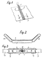
- la figure 1 est une vue en perspective représentant la jonction des deux extrémités d'un tapis transporteur au moyen de deux rangées d'agrafes de jonction et d'un axe assurant la réunion et l'articulation de celles-ci;
- la figure 2 est une vue schématique en coupe transversale, à échelle différente, d'un tapis transporteur en cours d'utilisation sur un convoyeur;
- la figure 3 est une vue en coupe longitudinale, à échelle differente, de la jonction représentée à la figure 1, cette vue correspondant à une coupe selon la ligne III-III de la figure 1;
- les figures 4 et 5 sont des vues en perspective, avec arrachement, de deux formes de réalisation différentes de l'axe flexible de jonction selon l'invention;
- la figure 6 est une vue schématique en perspective illustrant les conditions de flexion de l'axe représenté à la figure 4.
- Figure 1 is a perspective view showing the junction of the two ends of a conveyor belt by means of two rows of junction staples and an axis ensuring the meeting and articulation thereof;
- Figure 2 is a schematic cross-sectional view, on a different scale, of a conveyor belt in use on a conveyor;
- Figure 3 is a longitudinal sectional view, on a different scale, of the junction shown in Figure 1, this view corresponding to a section along the line III-III of Figure 1;
- Figures 4 and 5 are perspective views, broken away, of two different embodiments of the flexible junction axis according to the invention;
- FIG. 6 is a schematic perspective view illustrating the bending conditions of the axis shown in FIG. 4.
Comme représenté sur la figure 1, l'axe flexible 1 selon l'invention est destiné à assurer la réunion de deux rangées 2 d'agrafes métalliques disposées à cheval sur les extrémités 3 d'un tapis transporteur devant être fermé sur lui-même. Les agrafes 4 de ces deux rangées présentent une forme générale en U et elles sont disposées à cheval sur l'une et l'autre extrémités du tapis. Leur fixation est assurée par exemple par des crampons métalliques 5. Ces agrafes présentent des charnons 6 destinés à être imbriqués les uns entre les autres pour être réunis au moyen d'un axe 1 enfilé dans le passage formé par ces divers charnons après imbrication de ceux-ci (voir figures 1 et 3). Cet axe est flexible de façon à permettre l'incurvement du tapis transporteur dans le sens transversal, comme représenté à la figure 2. Dans la forme de réalisation représentée à la figure 4, l'axe 1 selon l'invention est constitué par la combinaison de trois éléments concentriques, à savoir:
- - une âme centrale constituée par un câble métallique 7 formé par le torsadage de plusieurs multi- rons 8 en fils métalliques,
- - une gaine intermédiaire 9 en matière plastique,
- - et enfin, une enveloppe externe 10, formée par le torsadage de plusieurs
fils 11 d'acier, ou autre métal approprié.
- a central core constituted by a
metallic cable 7 formed by the twisting of several multirons 8 made of metallic wires, - - an
intermediate sheath 9 made of plastic, - - And finally, an
outer casing 10, formed by the twisting ofseveral wires 11 of steel, or other suitable metal.
Il convient de noter que dans l'exemple représenté le sens du torsadage de cette enveloppe est inverse du sens de torsadage du câble central 7. Cependant, l'enveloppe externe pourrait également avoir le même sens de torsadage que le câble central 7.It should be noted that in the example shown the direction of twisting of this envelope is opposite to the direction of twisting of the
En pratique la gaine intermédiaire 9 est réalisée par extrusion directement autour du câble central 7, l'enveloppe externe 10 étant pour sa part torsadée ensuite sur cette gaine, de sorte que les fils d'aciers 11 de cette enveloppe viennent s'imprimer sur la surface externe de cette gaine en y formant des rainures hélicoïdales 12. La matière plastique utilisée pour la réalisation de la gaine intermédiaire 9 par extrusion peut être par exemple du polyéthylène.In practice, the
Compte-tenu de sa structure, cet axe présente la flexibilité voulue pour permettre au tapis transporteur 3 de s'incurver en forme d'auge sur les rouleaux de guidage 13 d'un convoyeur, comme représenté sur la figure 2. Néanmoins, cet axe présente une très grande résistance mécanique lui permettant de transmettre les efforts voulus de traction entre une extrémité et l'autre d'un tapis transporteur.Given its structure, this axis has the flexibility required to allow the
Cependant, la présence de la gaine externe 10 n'est pas un obstacle à la flexibilité du présent acte, - bien au contraire -. En effet, la réalisation de cet axe sous forme de deux éléments métalliques distincts - à savoir: l'âme interne et l'enveloppe externe - favorise sa flexibilité dans le sens transversal, car ces éléments peuvent glisser l'un sur l'autre pendant leur flexion. Du reste, l'interposition de la gaine intermédiaire 9 en matière plastique favorise ce glissement en évitant tout risque de grippage entre les deux éléments en cause, avec les inconvénients qui en seraient résulté, en l'occurrence: diminution de la flexibilité de l'axe et risque d'usure prématurée de ses éléments constitutifs. Le schéma de la figure 6 illustre le glissement qui peut se produire dans un tel cas pour un toron 11 déterminé de l'enveloppe externe 10, lequel toron peut occuper successivement les positions 11 b et 11c, du fait de sa différence de flexion par rapport à la flexion de l'âme interne 7.However, the presence of the
Dans une forme de réalisation avantageuse, la gaine intermédiaire 9 est réalisée en une matière plastique, par exemple du polyéthylène, chargée d'une graisse susceptible de migrer à l'extérieur sous l'effet des déformations imposées ultérieurement à cette gaine. Cette graisse peut être une graisse à base de silicone ou de bisufure de molybdène. Dans ce cas, l'axe selon l'invention est en mesure d'assurer la lubrification de sa surface de contact avec les charnons 6 des agrafes. En effet, les contraintes et déformations imposées à la gaine intermédiaire 9, lors de diverses flexions de l'axe, provoquent la migration de la graisse contenue à l'intérieur de cette gaine 10. Dans ces conditions cette graisse est amenée à fluer entre les monotorons 11 de l'enveloppe externe 10. Ceci l'amène donc à lubrifier la surface externe de cette enveloppe. Or, une très faible quantité de graisse suffit à assurer la lubrification voulue, de sorte qu'un axe flexible selon l'invention est susceptible d'assurer une bonne lubrification pendant une longue durée.In an advantageous embodiment, the
Une telle lubrification permet donc d'éviter les risques de grippage des charnons 6 des agrafes de jonction. Cette lubrification a également l'avantage de faciliter l'articulation des charnons 6, en évitant de la sorte une usure trop rapide de leur axe de jonction.Such lubrication therefore makes it possible to avoid the risks of seizing of the knuckles 6 of the junction staples. This lubrication also has the advantage of facilitating the articulation of the knuckles 6, thereby avoiding too rapid wear of their junction axis.
La figure 5 représente une autre forme de réalisation dans laquelle la structure de l'axe flexible correspondant la diffère de la précédente uniquement par le fait qu'au lieu d'être constitué par un câble 7, l'âme centrale consiste en un ressort métallique 14. Quant aux autres éléments costitutifs de cet axe 1 a, ils sont indentiques à ceux prévus précédemment puisqu'ils consistent en une enveloppe externe 10a identique à l'enveloppe 10, et une gaine intermédiaire 9a en matière plastique, identique à la gaine 9 de la figure 4.FIG. 5 represents another embodiment in which the structure of the corresponding flexible axis differs from the previous one only by the fact that instead of being constituted by a
De préférence, la matière plastique constituant cette gaine est également chargée d'une graisse susceptible de migrer à l'extérieur, Par ailleurs, de même que pour le câble 7 de la forme de réalisation selon la figure 4, le sens de torsadage de ce ressort est inverse du sens de torsadage des monotorons 11 de l'enveloppe externe 10 du câble correspondant.Preferably, the plastic material constituting this sheath is also charged with a grease capable of migrating to the outside. Furthermore, as for the
En effet, l'inversion de ces deux sens de torsadage est une des conditions pour obtenir que les déformations subies par l'âme interne et par l'enveloppe externe exercent, sur la garniture intermédiaire 9 ou 9a, des contraintes de nature appropriée pour provoquer la migration de la graisse contenue à l'intérieur de celle-ci. Bien que l'âme interne du câble selon la figure 5 soit constituée par un ressort métallique, on obtient donc le même résultat qu'avec la forme de réalisation de la figure 4.Indeed, the inversion of these two directions of twisting is one of the conditions for obtaining that the deformations undergone by the internal core and by the external envelope exert, on the
Il faut observer que les monotorons de l'enveloppe externe 7 ou 7a de chacune des formes de réalisation décrites ci-dessus, peuvent avoir une section autre que circulaire, par exemple une section de forme telle que la surface de cette enveloppe soit à peu près lisse, de façon à réaliser une excellente surface d'appui pour les charnons 6 des agrafes de jonction. Du reste, l'axe flexible de jonction selon l'invention n'est pas limité aux deux formes de réalisation représentées aus figures 4et 5, celles-ci ayant été décrites à simple titre d'exemple indicatif.It should be observed that the monotorons of the
Claims (3)
Applications Claiming Priority (2)
| Application Number | Priority Date | Filing Date | Title |
|---|---|---|---|
| FR8410026A FR2566477B1 (en) | 1984-06-26 | 1984-06-26 | FLEXIBLE AXIS FOR JOINING AND JOINING THE JUNCTION STAPLES OF A CONVEYOR BELT |
| FR8410026 | 1984-06-26 |
Publications (2)
| Publication Number | Publication Date |
|---|---|
| EP0166645A1 EP0166645A1 (en) | 1986-01-02 |
| EP0166645B1 true EP0166645B1 (en) | 1988-05-11 |
Family
ID=9305429
Family Applications (1)
| Application Number | Title | Priority Date | Filing Date |
|---|---|---|---|
| EP85401112A Expired EP0166645B1 (en) | 1984-06-26 | 1985-06-06 | Flexible axis for articulatedly connecting hooklike locking means of a conveyor belt |
Country Status (8)
| Country | Link |
|---|---|
| US (1) | US4671403A (en) |
| EP (1) | EP0166645B1 (en) |
| JP (1) | JPS6112504A (en) |
| AU (1) | AU4348385A (en) |
| CA (1) | CA1231913A (en) |
| DE (1) | DE3562658D1 (en) |
| FR (1) | FR2566477B1 (en) |
| ZA (1) | ZA854405B (en) |
Families Citing this family (26)
| Publication number | Priority date | Publication date | Assignee | Title |
|---|---|---|---|---|
| US5049425A (en) * | 1989-01-04 | 1991-09-17 | Abany International Corporation | Porous yarn for OMS pintles |
| EP0437639B1 (en) * | 1989-12-14 | 1993-11-10 | Goro S.A. | Seal for the connection of two parts of a conveyor belt and connection comprising such a seal |
| FR2664009B1 (en) * | 1990-06-27 | 1995-07-13 | Goro Sa | STAPLES FOR JOINING THE END OF A CONVEYOR MAT AND APPARATUS FOR FIXING SUCH STAPLES. |
| DE9016586U1 (en) * | 1990-12-06 | 1991-02-21 | Muehlen Sohn Gmbh & Co., 7906 Blaustein, De | |
| DE4110818C1 (en) * | 1991-04-04 | 1992-09-17 | Mato Maschinen- Und Metallwarenfabrik Curt Matthaei Gmbh & Co Kg, 6050 Offenbach, De | |
| FR2701300B1 (en) * | 1993-02-09 | 1995-03-31 | Aser Sarl | Joining device for conveyor belt. |
| DE4318836A1 (en) * | 1993-06-07 | 1994-12-08 | Mato Masch & Metallwaren | Connection element for conveyor belts |
| FR2706964B1 (en) * | 1993-06-21 | 1995-09-01 | Aser Sarl | |
| AU685200B2 (en) * | 1994-02-02 | 1998-01-15 | Mato Maschinen- Und Metallwarenfabrik Curt Matthaei Gmbh & Co Kg | Coupling bar |
| IN188123B (en) * | 1995-04-20 | 2002-08-24 | Vi Goro Sarl | |
| DE19531432A1 (en) * | 1995-08-27 | 1997-03-06 | Mato Masch & Metallwaren | Conveyor belt for use in a conveyor with a trough zone |
| US5620085A (en) * | 1996-02-02 | 1997-04-15 | General Signal Corporation | Spliced conveyer belt assembly |
| US5896981A (en) * | 1997-01-03 | 1999-04-27 | General Signal Corporation | Spliced conveyer belt method and apparatus |
| DE19702005A1 (en) * | 1997-01-22 | 1998-07-23 | Goro Sa | Clutch rod |
| DE19820717A1 (en) * | 1998-05-11 | 1999-11-18 | Mato Masch & Metallwaren | Connection of two ends of a conveyor belt |
| FR2792050B1 (en) * | 1999-04-12 | 2001-06-08 | Aser Sarl | CLAW CLIP FOR CONVEYOR BELT JUNCTIONS |
| US6830174B2 (en) | 2000-08-30 | 2004-12-14 | Cerebral Vascular Applications, Inc. | Medical instrument |
| US6755338B2 (en) | 2001-08-29 | 2004-06-29 | Cerebral Vascular Applications, Inc. | Medical instrument |
| US6687961B2 (en) * | 2002-02-20 | 2004-02-10 | Tuthill Controls Group | Hinge pin connector |
| AU2003225637A1 (en) * | 2002-03-04 | 2003-09-22 | Flexible Steel Lacing Company | Conveyor belt fasteners |
| EP2423535A3 (en) * | 2010-08-23 | 2012-05-09 | Innova Patent GmbH | Conveyor belt for a conveyor belt assembly |
| CN104444067A (en) * | 2013-09-16 | 2015-03-25 | 无锡百科知识产权有限公司 | Method for connecting belt conveying line |
| WO2016028586A1 (en) | 2014-08-18 | 2016-02-25 | Flexible Steel Lacing Company | Conveyor belt fastener and method of manufacture |
| USD808253S1 (en) | 2014-08-18 | 2018-01-23 | Flexible Steel Lacing Company | Fastener for a conveyor belt |
| DE102015212748A1 (en) * | 2015-07-08 | 2017-01-12 | Contitech Transportbandsysteme Gmbh | Belt or belt segment |
| DE102015214395A1 (en) * | 2015-07-29 | 2017-02-02 | Contitech Transportbandsysteme Gmbh | Belt or belt segment |
Family Cites Families (11)
| Publication number | Priority date | Publication date | Assignee | Title |
|---|---|---|---|---|
| US2370884A (en) * | 1943-08-05 | 1945-03-06 | Smith Joseph Leigh | Flexible shaft |
| DE1234459B (en) * | 1963-06-01 | 1967-02-16 | Scapa Dryers Ltd | Connecting bolts for a hinge-like belt connection for belts and other flat fabrics for commercial purposes, in particular for paper machine drying felts |
| US3319217A (en) * | 1966-02-25 | 1967-05-09 | New Twist Connector Corp | Spirally wound pin connector |
| US4007303A (en) * | 1970-10-30 | 1977-02-08 | Fitztuchverwaltungs-Gesellschaft Mit Beschrankter Haftung | Method of making pintle wire for high load hinge connections |
| FR2118395A5 (en) * | 1970-12-17 | 1972-07-28 | Minet | |
| DE2240013C3 (en) * | 1972-08-14 | 1982-01-14 | Mato Maschinen- Und Metallwarenfabrik Curt Matthaei Gmbh & Co Kg, 6050 Offenbach | Coupling rod |
| DE2449792B1 (en) * | 1974-10-19 | 1976-02-12 | Heimbach Gmbh Thomas Josef | Seamless paper web wire screen joint - formed by helical wire portions joined by pin with wire helix and pin coated with polyamide or polyarylsulphone |
| DE2507474C2 (en) * | 1975-02-21 | 1983-12-08 | Mato Maschinen- Und Metallwarenfabrik Curt Matthaei Gmbh & Co Kg, 6050 Offenbach | Coupling rod for connecting the ends of conveyor belts |
| US4024605A (en) * | 1975-12-18 | 1977-05-24 | Flexible Steel Lacing Company | Flexible hinge pin |
| DE2920461C2 (en) * | 1979-05-21 | 1981-09-03 | Mato Maschinen- Und Metallwarenfabrik Curt Matthaei Gmbh & Co Kg, 6050 Offenbach | Connector strips for conveyor belts |
| US4344209A (en) * | 1979-10-22 | 1982-08-17 | Scapa Dryers, Inc. | In-line clipper seam |
-
1984
- 1984-06-26 FR FR8410026A patent/FR2566477B1/en not_active Expired
-
1985
- 1985-06-06 EP EP85401112A patent/EP0166645B1/en not_active Expired
- 1985-06-06 DE DE8585401112T patent/DE3562658D1/en not_active Expired
- 1985-06-11 ZA ZA854405A patent/ZA854405B/en unknown
- 1985-06-12 AU AU43483/85A patent/AU4348385A/en not_active Abandoned
- 1985-06-12 US US06/743,893 patent/US4671403A/en not_active Expired - Fee Related
- 1985-06-19 CA CA000484495A patent/CA1231913A/en not_active Expired
- 1985-06-25 JP JP60138842A patent/JPS6112504A/en active Pending
Also Published As
| Publication number | Publication date |
|---|---|
| CA1231913A (en) | 1988-01-26 |
| AU4348385A (en) | 1986-01-02 |
| FR2566477B1 (en) | 1987-08-21 |
| JPS6112504A (en) | 1986-01-20 |
| ZA854405B (en) | 1986-02-26 |
| EP0166645A1 (en) | 1986-01-02 |
| DE3562658D1 (en) | 1988-06-16 |
| US4671403A (en) | 1987-06-09 |
| FR2566477A1 (en) | 1985-12-27 |
Similar Documents
| Publication | Publication Date | Title |
|---|---|---|
| EP0166645B1 (en) | Flexible axis for articulatedly connecting hooklike locking means of a conveyor belt | |
| LU84984A1 (en) | CABLES AND THEIR MANUFACTURING METHOD | |
| FR2713492A1 (en) | Flexible tubular guide | |
| FR2627068A1 (en) | BRUSH FOR APPLYING A MAKE-UP PRODUCT, PARTICULARLY MASCARA, AND RESERVOIR OF PRODUCT EQUIPPED WITH SUCH A BRUSH | |
| FR2473136A1 (en) | FIXING NECK, IN PARTICULAR ELECTRIC CABLES | |
| FR2757642A1 (en) | OPTICAL FIBER CABLE WITH DISSYMMETRIC STRUCTURE | |
| LU83406A1 (en) | TOOTHED BELT | |
| EP0187061B1 (en) | Hinge fastener for joining together two complementary series of fastener clips | |
| FR2511583A1 (en) | WATERPROOF ZIPPER HANGING STRIP | |
| FR2566475A1 (en) | DEFORMABLE EAR FOR CLAMPS AND TIGHTENING COLLAR COMPRISING | |
| FR2624940A1 (en) | JUNCTION AXIS FOR CONNECTING THE END OF A CARRIER BELT OR THE LIKE | |
| EP0437639B1 (en) | Seal for the connection of two parts of a conveyor belt and connection comprising such a seal | |
| FR2501815A1 (en) | TRAPEZOIDAL TRANSMISSION BELT, IN PARTICULAR FOR A SPEED DRIVE, COMPRISING MEANS FOR UNIFORMIZING CONTACT PRESSURES ON ITS TWO CONVERGENT FLANKS | |
| FR2657511A1 (en) | MASCARA BRUSH FOR LACQUERS AND PROCESS FOR MAKING SAME. | |
| FR2769120A1 (en) | Multi-core electrical cable for use with medical appliances | |
| EP0185581B1 (en) | Flexible tubular device for transmitting longitudinal forces | |
| FR2749570A1 (en) | Flight conveyor cable for conduit scraping conveyor used e.g. for conveying food to feeding areas in stables | |
| FR2728108A1 (en) | ELECTRICAL PLUG OF THE ENGLISH PLUG TYPE | |
| FR2633402A1 (en) | TRACTION-RESISTANT OPTICAL CONDUCTOR | |
| CH345590A (en) | Conveyor belt | |
| FR2551253A1 (en) | Transmission cable, especially an optical transmission cable, comprising an elastic element. | |
| FR2509398A1 (en) | ELASTIC COUPLING IN ROTATION | |
| FR2564635A1 (en) | TRACTION ARMOR FOR CABLES, AND CABLE FOR UNDERWATER USE WITH SUCH ARMOR | |
| CH661800A5 (en) | External protective armouring for telecommunication cable | |
| BE897633A (en) | Cables and manufacturing process |
Legal Events
| Date | Code | Title | Description |
|---|---|---|---|
| PUAI | Public reference made under article 153(3) epc to a published international application that has entered the european phase |
Free format text: ORIGINAL CODE: 0009012 |
|
| AK | Designated contracting states |
Designated state(s): BE DE FR GB IT |
|
| 17P | Request for examination filed |
Effective date: 19860426 |
|
| 17Q | First examination report despatched |
Effective date: 19870505 |
|
| GRAA | (expected) grant |
Free format text: ORIGINAL CODE: 0009210 |
|
| AK | Designated contracting states |
Kind code of ref document: B1 Designated state(s): BE DE FR GB IT |
|
| PG25 | Lapsed in a contracting state [announced via postgrant information from national office to epo] |
Ref country code: IT Free format text: LAPSE BECAUSE OF FAILURE TO SUBMIT A TRANSLATION OF THE DESCRIPTION OR TO PAY THE FEE WITHIN THE PRESCRIBED TIME-LIMIT;WARNING: LAPSES OF ITALIAN PATENTS WITH EFFECTIVE DATE BEFORE 2007 MAY HAVE OCCURRED AT ANY TIME BEFORE 2007. THE CORRECT EFFECTIVE DATE MAY BE DIFFERENT FROM THE ONE RECORDED. Effective date: 19880511 |
|
| GBT | Gb: translation of ep patent filed (gb section 77(6)(a)/1977) | ||
| REF | Corresponds to: |
Ref document number: 3562658 Country of ref document: DE Date of ref document: 19880616 |
|
| BERE | Be: lapsed |
Owner name: GORO S.A. Effective date: 19880630 |
|
| PLBE | No opposition filed within time limit |
Free format text: ORIGINAL CODE: 0009261 |
|
| STAA | Information on the status of an ep patent application or granted ep patent |
Free format text: STATUS: NO OPPOSITION FILED WITHIN TIME LIMIT |
|
| 26N | No opposition filed | ||
| PG25 | Lapsed in a contracting state [announced via postgrant information from national office to epo] |
Ref country code: BE Effective date: 19890630 |
|
| PGFP | Annual fee paid to national office [announced via postgrant information from national office to epo] |
Ref country code: FR Payment date: 19910627 Year of fee payment: 7 |
|
| PGFP | Annual fee paid to national office [announced via postgrant information from national office to epo] |
Ref country code: DE Payment date: 19910628 Year of fee payment: 7 |
|
| PGFP | Annual fee paid to national office [announced via postgrant information from national office to epo] |
Ref country code: GB Payment date: 19910703 Year of fee payment: 7 |
|
| PG25 | Lapsed in a contracting state [announced via postgrant information from national office to epo] |
Ref country code: GB Effective date: 19920606 |
|
| GBPC | Gb: european patent ceased through non-payment of renewal fee |
Effective date: 19920606 |
|
| PG25 | Lapsed in a contracting state [announced via postgrant information from national office to epo] |
Ref country code: FR Effective date: 19930226 |
|
| PG25 | Lapsed in a contracting state [announced via postgrant information from national office to epo] |
Ref country code: DE Effective date: 19930302 |
|
| REG | Reference to a national code |
Ref country code: FR Ref legal event code: ST |