EP0166361A1 - Feuerverzinkungsanlage - Google Patents
Feuerverzinkungsanlage Download PDFInfo
- Publication number
- EP0166361A1 EP0166361A1 EP19850107540 EP85107540A EP0166361A1 EP 0166361 A1 EP0166361 A1 EP 0166361A1 EP 19850107540 EP19850107540 EP 19850107540 EP 85107540 A EP85107540 A EP 85107540A EP 0166361 A1 EP0166361 A1 EP 0166361A1
- Authority
- EP
- European Patent Office
- Prior art keywords
- hall
- crane
- pickling
- plant according
- running
- Prior art date
- Legal status (The legal status is an assumption and is not a legal conclusion. Google has not performed a legal analysis and makes no representation as to the accuracy of the status listed.)
- Ceased
Links
- 238000005246 galvanizing Methods 0.000 title claims abstract description 16
- 238000005554 pickling Methods 0.000 claims abstract description 34
- XLYOFNOQVPJJNP-UHFFFAOYSA-N water Substances O XLYOFNOQVPJJNP-UHFFFAOYSA-N 0.000 claims abstract description 15
- 239000000463 material Substances 0.000 claims abstract description 12
- 238000001035 drying Methods 0.000 claims abstract description 9
- 230000032258 transport Effects 0.000 claims description 6
- 238000012432 intermediate storage Methods 0.000 claims description 4
- 229910000831 Steel Inorganic materials 0.000 description 1
- 239000007788 liquid Substances 0.000 description 1
- 238000012423 maintenance Methods 0.000 description 1
- 239000010959 steel Substances 0.000 description 1
- 230000007704 transition Effects 0.000 description 1
Images
Classifications
-
- C—CHEMISTRY; METALLURGY
- C23—COATING METALLIC MATERIAL; COATING MATERIAL WITH METALLIC MATERIAL; CHEMICAL SURFACE TREATMENT; DIFFUSION TREATMENT OF METALLIC MATERIAL; COATING BY VACUUM EVAPORATION, BY SPUTTERING, BY ION IMPLANTATION OR BY CHEMICAL VAPOUR DEPOSITION, IN GENERAL; INHIBITING CORROSION OF METALLIC MATERIAL OR INCRUSTATION IN GENERAL
- C23C—COATING METALLIC MATERIAL; COATING MATERIAL WITH METALLIC MATERIAL; SURFACE TREATMENT OF METALLIC MATERIAL BY DIFFUSION INTO THE SURFACE, BY CHEMICAL CONVERSION OR SUBSTITUTION; COATING BY VACUUM EVAPORATION, BY SPUTTERING, BY ION IMPLANTATION OR BY CHEMICAL VAPOUR DEPOSITION, IN GENERAL
- C23C2/00—Hot-dipping or immersion processes for applying the coating material in the molten state without affecting the shape; Apparatus therefor
- C23C2/34—Hot-dipping or immersion processes for applying the coating material in the molten state without affecting the shape; Apparatus therefor characterised by the shape of the material to be treated
Definitions
- the invention relates to a hot-dip galvanizing plant which has, in a rectangular hall provided with at least one bridge crane running in its longitudinal direction, pickling trays, a drying oven, a galvanizing oven and a water bath, which are to be loaded with the material hanging on trusses one after the other.
- the invention has for its object to provide such a system with the cheapest possible use of space and short, unimpeded material flow.
- the hall preferably has two aisles and there is such a bridge crane in each ship.
- Each aforementioned crane can also be a multiple on the relevant crane runway, i.e. have several bridges or consoles.
- the console crane is preferably provided two or three times.
- truss supports for attaching the goods should be arranged on the other long side of the hall and from one on this long side also under the above-mentioned bridge crane running in the longitudinal direction of the hall - the only one or that in the ship in question - to the Escape of the pickling tubs running second console crane be painted over.
- a walking beam conveyor which feeds them is arranged for the traverses covered with the material, the support plane for the traverses of which is lower than the overhead crane of the pickling tubs and which overlaps with the latter.
- a corresponding arrangement can be made on the other side of the pickling troughs with a second walking beam conveyor that transports them, the support plane of which lies lower than the overhead crane of the pickling troughs and than the first-mentioned console crane and which overlaps with these two cranes.
- the walking beam conveyor (s) and the truss support can in turn be present several times, preferably twice, namely for two parallel rows of pickling tanks.
- Another walking beam conveyor can be arranged to convey away from the water bath perpendicular to the long side of the hall in order to drain the material.
- a spinner for small parts is to be available, it is conveniently arranged between the galvanizing furnace and the water bath, moving a bit into the hall from the long side of the hall so that the small parts can be removed and packed where there is more space .
- a floor conveyor for empty traverses across the hall in the material conveying direction behind the water bath such as a carriage that can be moved on rails.
- This conveyor system is then followed in the circuit by the truss supports which are approximately opposite the drying oven, the galvanizing oven and the water bath, for attaching the goods.
- this connection does not always have to be immediate.
- a smaller or larger truss bearing can also be interposed at a suitable point.
- Behind the floor conveyor in the hall there are conveniently intermediate storage and loading areas for the galvanized and galvanized goods, for the latter preferably with truss supports on which the goods can be removed from the trusses.
- a gate for transport in and out is best arranged on the end of the hall opposite the pickling baths;
- a gate for delivery in one and a gate for removal in the other ship is provided in a two-aisle hall so that the flow of material remains separate from start to finish.
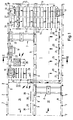
- a two-aisle hall 1 has on its long sides two rows of supports 2 and in the middle a row of supports 3 which carry roof racks 4.
- the drawing is limited to this steel structure, the walls and roof are not shown.
- Each of the two ships is completely covered by a bridge crane 7 or 8, the crane run of which runs on the supports 2 and 3 and is indicated by dash-dotted lines at 9.
- a gantry crane system is arranged under the overhead crane 7 or 8, one with three mobile jib brackets 10 and the other with a mobile jib bracket 11.
- the crane runway 12 in question which extends on the supports 2, also forms part of the arrangement the top of the crane runway 9 of the bridge crane 7 and 8 respectively.
- the overhead crane 14 is the deepest of the crane systems. It extends at one end, as can be seen on the left in FIG. 2, under the bracket brackets 10.
- the overhead crane 14 overlaps with an even lower walking beam conveyor 17, which in turn overlaps with the reach of the jib bracket 11.
- the walking beam conveyor 17 is also duplicated in accordance with the double row of pickling tanks 13. It is not actually drawn, but is clearly recognizable by the crossbeams 18 lying on it with a hint of the attached goods 19 in FIG. 2.
- crossbeam supports 20 arranged along one longitudinal side wall are shown only by the crossbeams 21 lying on them.
- the crossbar supports 20 are swept by the bracket 11.
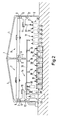
- bracket brackets 10 On the other side wall of the hall, swept by the bracket brackets 10, there is a drying oven 22, a galvanizing oven 23, a water bath 24 and between the latter two a spinner 25 which can be moved into the hall on rails 26 from the side wall.
- Two truss supports 28, again only represented by trusses 27, behind the pickling basin 13 are also covered by the bracket brackets 10 and at the same time by the overhead crane 14.
- the water bath 24 is followed by a walking beam conveyor 30, which is shown only by cross members 29 lying on it.
- a carriage 31 for empty trusses can be moved on rails 32 from one to the other long side of the hall.
- the space 33 between the rails 32 and the gate 5 is used for unloading and intermediate storage of the goods to be galvanized.
- the space 34 between the rails 32 and the gate 6 is used to remove the galvanized goods from cross members 36 lying on cross member supports 35 and for intermediate storage and loading for removal.
- the goods unloaded and, if necessary, stored in place 33 are hung by means of the overhead crane 8 on the trusses 21 lying on the truss supports 20.
- the boom bracket 11 picks up with its lifting mechanism 37 (FIG. 2) the traverses covered with the material and places them on the walking beam conveyor 17.
- the overhead crane 14 takes them away from this and brings them, in accordance with the control program, into a pickling tank 13 the trusses rest on its edge, as can be seen at 38, while the material hangs into the pickling liquid.
- the overhead crane 14 picks up the trusses again, as shown at 39, and places them on the truss support 28. The material drips there.
- the overhead crane 7 takes over the transport to the truss supports 35 The overhead crane 7 then also places the empty trusses on the trolley 31, with which they cross over to the other half of the hall and into the area of the overhead crane 8.
- the bridge crane 7 can also be used instead of the bracket crane system with the jib brackets 10 to transport particularly heavy goods.
- the small parts are packed on the centrifugal machine 25. Otherwise, the goods are packed and loaded on place 34.
Landscapes
- Chemical & Material Sciences (AREA)
- Chemical Kinetics & Catalysis (AREA)
- Engineering & Computer Science (AREA)
- Materials Engineering (AREA)
- Mechanical Engineering (AREA)
- Metallurgy (AREA)
- Organic Chemistry (AREA)
- Coating With Molten Metal (AREA)
Applications Claiming Priority (2)
| Application Number | Priority Date | Filing Date | Title |
|---|---|---|---|
| DE3423476 | 1984-06-26 | ||
| DE19843423476 DE3423476C2 (de) | 1984-06-26 | 1984-06-26 | Feuerverzinkungsanlage |
Publications (1)
| Publication Number | Publication Date |
|---|---|
| EP0166361A1 true EP0166361A1 (de) | 1986-01-02 |
Family
ID=6239153
Family Applications (1)
| Application Number | Title | Priority Date | Filing Date |
|---|---|---|---|
| EP19850107540 Ceased EP0166361A1 (de) | 1984-06-26 | 1985-06-19 | Feuerverzinkungsanlage |
Country Status (2)
| Country | Link |
|---|---|
| EP (1) | EP0166361A1 (OSRAM) |
| DE (1) | DE3423476C2 (OSRAM) |
Cited By (2)
| Publication number | Priority date | Publication date | Assignee | Title |
|---|---|---|---|---|
| DE4138559A1 (de) * | 1991-11-23 | 1993-05-27 | Wolfgang Dipl Ing Gebhardt | Fahrbarer konsolkran |
| CN117403162A (zh) * | 2023-10-30 | 2024-01-16 | 聊城鑫泰机床有限公司 | 一种顶托自动热镀锌系统 |
Citations (4)
| Publication number | Priority date | Publication date | Assignee | Title |
|---|---|---|---|---|
| DD78459A (OSRAM) * | ||||
| GB1145518A (en) * | 1965-11-26 | 1969-03-19 | Heinz Strecke | Improvements in or relating to a dipping or plating plant |
| US3961712A (en) * | 1974-10-31 | 1976-06-08 | International Paper Company | Industrial building structure system |
| DE2936925A1 (de) * | 1979-09-12 | 1981-03-19 | Hans Weigel GmbH & Co KG, 8500 Nürnberg | Vorrichtung zur tauchbehandlung von werkstuecken, insbesondere zum verzinken, sowie greifvorrichtung hierfuer |
-
1984
- 1984-06-26 DE DE19843423476 patent/DE3423476C2/de not_active Expired
-
1985
- 1985-06-19 EP EP19850107540 patent/EP0166361A1/de not_active Ceased
Patent Citations (4)
| Publication number | Priority date | Publication date | Assignee | Title |
|---|---|---|---|---|
| DD78459A (OSRAM) * | ||||
| GB1145518A (en) * | 1965-11-26 | 1969-03-19 | Heinz Strecke | Improvements in or relating to a dipping or plating plant |
| US3961712A (en) * | 1974-10-31 | 1976-06-08 | International Paper Company | Industrial building structure system |
| DE2936925A1 (de) * | 1979-09-12 | 1981-03-19 | Hans Weigel GmbH & Co KG, 8500 Nürnberg | Vorrichtung zur tauchbehandlung von werkstuecken, insbesondere zum verzinken, sowie greifvorrichtung hierfuer |
Cited By (2)
| Publication number | Priority date | Publication date | Assignee | Title |
|---|---|---|---|---|
| DE4138559A1 (de) * | 1991-11-23 | 1993-05-27 | Wolfgang Dipl Ing Gebhardt | Fahrbarer konsolkran |
| CN117403162A (zh) * | 2023-10-30 | 2024-01-16 | 聊城鑫泰机床有限公司 | 一种顶托自动热镀锌系统 |
Also Published As
| Publication number | Publication date |
|---|---|
| DE3423476C2 (de) | 1986-06-19 |
| DE3423476A1 (de) | 1986-02-13 |
| DE3423476C3 (OSRAM) | 1992-08-27 |
Similar Documents
| Publication | Publication Date | Title |
|---|---|---|
| DE2539968A1 (de) | Verladevorrichtung, insbesondere fuer container | |
| DE1003131B (de) | Stapeleinrichtung | |
| DE102011013415B4 (de) | Tauchbehandlungsanlage für Fahrzeugkarosserien und Verfahren zum Betreiben einer solchen | |
| DE3423476C3 (OSRAM) | ||
| DE4125977A1 (de) | Feuerverzinkungsanlage | |
| DE1508298B2 (de) | Stahlwerk | |
| DE1902638A1 (de) | Frachttransportvorrichtung | |
| DE1130249B (de) | Verfahren und Vorrichtung zum Beizen von band- oder drahtfoermigem Gut | |
| DE3147695A1 (de) | Anlage zur korrosionsschutz-vorbehandlung | |
| DE19950892A1 (de) | Vorrichtung zur Behandlung der Oberfläche von Gegenständen | |
| DE2146851C3 (de) | Anlage zum Behandeln, insbesondere zum Beizen von Metallen | |
| DE19740513A1 (de) | Lastenverladekran, insbesondere Containerverladekran | |
| DE2911188A1 (de) | Anlage zur galvanotechnischen behandlung von gegenstaenden | |
| DE1043748B (de) | Automatisch arbeitende Galvanisieranlage | |
| DE1556204A1 (de) | Vorrichtung zum Entladen von Schuettgut aus einem Frachtkahn | |
| DE740178C (de) | Tauchvorrichtung | |
| DE871271C (de) | Foerderanlage fuer Rueben od. dgl. | |
| DE3030307A1 (de) | Vorrichtung zum foerdern fester oder fluessiger stoffe, insbesondere zum beschicken eines schachtofens | |
| DE463966C (de) | Uferdoppelkran | |
| DE2836107A1 (de) | Verladekran | |
| DE2918141B1 (de) | Anordnung zur Manipulation von Werkstuecktraegern in Anlagen fuer die galvanotechnische Behandlung von Werkstuecken | |
| EP0104211B1 (de) | Vorrichtung zur zusammenstellung von materialkommissionen aus in einer wabenregalanlage eingelagertem lagergut | |
| DE1006234B (de) | Galvanisiereinrichtung | |
| DD276629A1 (de) | Einrichtung zur automatischen oberflaechenbehandlung von kleincontainern und einzelteilen | |
| DE1053964B (de) | Vorrichtung zum Heben und Verfahren von Teilen einer Lukenabdeckung auf Binnenschiffen |
Legal Events
| Date | Code | Title | Description |
|---|---|---|---|
| PUAI | Public reference made under article 153(3) epc to a published international application that has entered the european phase |
Free format text: ORIGINAL CODE: 0009012 |
|
| AK | Designated contracting states |
Designated state(s): AT BE CH DE FR IT LI NL |
|
| 17P | Request for examination filed |
Effective date: 19860116 |
|
| 17Q | First examination report despatched |
Effective date: 19861205 |
|
| STAA | Information on the status of an ep patent application or granted ep patent |
Free format text: STATUS: THE APPLICATION HAS BEEN REFUSED |
|
| 18R | Application refused |
Effective date: 19870606 |