EP0165747A1 - Maschine zur Herstellung von kleinen Papierheften - Google Patents
Maschine zur Herstellung von kleinen Papierheften Download PDFInfo
- Publication number
- EP0165747A1 EP0165747A1 EP85304051A EP85304051A EP0165747A1 EP 0165747 A1 EP0165747 A1 EP 0165747A1 EP 85304051 A EP85304051 A EP 85304051A EP 85304051 A EP85304051 A EP 85304051A EP 0165747 A1 EP0165747 A1 EP 0165747A1
- Authority
- EP
- European Patent Office
- Prior art keywords
- strand
- station
- cutting
- paper
- knife
- Prior art date
- Legal status (The legal status is an assumption and is not a legal conclusion. Google has not performed a legal analysis and makes no representation as to the accuracy of the status listed.)
- Granted
Links
- 230000007246 mechanism Effects 0.000 claims description 15
- 238000011144 upstream manufacturing Methods 0.000 claims description 5
- 235000019504 cigarettes Nutrition 0.000 abstract description 4
- 239000000123 paper Substances 0.000 description 30
- 230000009471 action Effects 0.000 description 3
- 239000000969 carrier Substances 0.000 description 3
- 230000007480 spreading Effects 0.000 description 2
- 239000004429 Calibre Substances 0.000 description 1
- 229910000831 Steel Inorganic materials 0.000 description 1
- 230000008901 benefit Effects 0.000 description 1
- 210000001520 comb Anatomy 0.000 description 1
- 230000014759 maintenance of location Effects 0.000 description 1
- 239000000463 material Substances 0.000 description 1
- 230000004048 modification Effects 0.000 description 1
- 238000012986 modification Methods 0.000 description 1
- 230000010355 oscillation Effects 0.000 description 1
- 238000005096 rolling process Methods 0.000 description 1
- 238000010008 shearing Methods 0.000 description 1
- 239000010959 steel Substances 0.000 description 1
- 239000004575 stone Substances 0.000 description 1
Images


Classifications
-
- B—PERFORMING OPERATIONS; TRANSPORTING
- B65—CONVEYING; PACKING; STORING; HANDLING THIN OR FILAMENTARY MATERIAL
- B65H—HANDLING THIN OR FILAMENTARY MATERIAL, e.g. SHEETS, WEBS, CABLES
- B65H45/00—Folding thin material
- B65H45/12—Folding articles or webs with application of pressure to define or form crease lines
- B65H45/24—Interfolding sheets, e.g. cigarette or toilet papers
-
- Y—GENERAL TAGGING OF NEW TECHNOLOGICAL DEVELOPMENTS; GENERAL TAGGING OF CROSS-SECTIONAL TECHNOLOGIES SPANNING OVER SEVERAL SECTIONS OF THE IPC; TECHNICAL SUBJECTS COVERED BY FORMER USPC CROSS-REFERENCE ART COLLECTIONS [XRACs] AND DIGESTS
- Y10—TECHNICAL SUBJECTS COVERED BY FORMER USPC
- Y10T—TECHNICAL SUBJECTS COVERED BY FORMER US CLASSIFICATION
- Y10T83/00—Cutting
- Y10T83/465—Cutting motion of tool has component in direction of moving work
- Y10T83/4757—Tool carrier shuttles rectilinearly parallel to direction of work feed
- Y10T83/4763—Both members of cutting pair on same carrier
-
- Y—GENERAL TAGGING OF NEW TECHNOLOGICAL DEVELOPMENTS; GENERAL TAGGING OF CROSS-SECTIONAL TECHNOLOGIES SPANNING OVER SEVERAL SECTIONS OF THE IPC; TECHNICAL SUBJECTS COVERED BY FORMER USPC CROSS-REFERENCE ART COLLECTIONS [XRACs] AND DIGESTS
- Y10—TECHNICAL SUBJECTS COVERED BY FORMER USPC
- Y10T—TECHNICAL SUBJECTS COVERED BY FORMER US CLASSIFICATION
- Y10T83/00—Cutting
- Y10T83/485—Cutter with timed stroke relative to moving work
- Y10T83/503—With plural tool stations
-
- Y—GENERAL TAGGING OF NEW TECHNOLOGICAL DEVELOPMENTS; GENERAL TAGGING OF CROSS-SECTIONAL TECHNOLOGIES SPANNING OVER SEVERAL SECTIONS OF THE IPC; TECHNICAL SUBJECTS COVERED BY FORMER USPC CROSS-REFERENCE ART COLLECTIONS [XRACs] AND DIGESTS
- Y10—TECHNICAL SUBJECTS COVERED BY FORMER USPC
- Y10T—TECHNICAL SUBJECTS COVERED BY FORMER US CLASSIFICATION
- Y10T83/00—Cutting
- Y10T83/525—Operation controlled by detector means responsive to work
- Y10T83/54—Actuation of tool controlled by work-driven means to measure work length
Definitions
- This invention relates to a machine for making paper booklets which is particularly, though not exclusively, intended for making booklets of interleaved cigarette paper.
- Patent Specification No. GB-A-688144 Korean Patent Specification No. GB-A-688144 (Korber) to make booklets of folded and zig-zag interleaved cigarette papers by withdrawing paper strip from a plurality of supply rolls or bobbins, folding and interleaving the strips by passage through a succession of combs to form a folded and-interleaved strand, and cutting the strand to form booklets.
- the machine employed by Korber had a stationary cutting knife which was impractical for high speed operation and did not make a clean transverse cut through the strand which is required to move continuously.
- Kantner describes a similar machine in which the knife is mounted on a movable knife plate carried by a platform that is reciprocally movable in a direction parallel to the direction of travel of the strand of interleaved paper strips.
- a cylinder or other means carried by the platform reciprocally moves the knife plate towards or away from the strand so that the knife follows the movement of the strand as it severs the strip.
- a pusher plate carried by and movable with the knife plate displaces a severed booklet or packet sideways with respect to the line of travel of the strand.
- the Kastner machine still presents a number of disadvantages.
- Reciprocation of the platform is by an eccentric on a drive wheel that is coupled to the platform by a pivoted link, so that the platform does not match the speed of the strand throughout its rearward stroke, but instead its velocity varies in simple harmonic motion. Since the knife is moved towards and away from the strand without any component of motion across it, cutting is not as efficient as it could be. Cut booklets are discharged sideways into a magazine which is joined to the reciprocating platform by means of a flexible portion, which is essential because movement of the pusher is not separated from that of the knife.
- the solution adopted by the. applicants is to bring the rotatory movement onto the moving "platform" or cutting station and to use that movement to operate the cutting knife.
- rotation of a driven member in the cutting station may be transmitted to the knife by means of a cam and follower, by means of gearing or by means of a chain or belt.
- the knife can be driven positively from the same drive that reciprocates the cutting station, and the desirable guillotine-like cutting action may be achieved.
- the invention provides a machine for performing an operation on a paper strand including means for forming leaves of paper into a strand, a station in the path of the strand, means in the station for performing an operation on the strand, drive means for continuously advancing the strand through the station and for reciprocating the station along the strand so that a booklet length of the strand enters the station while the station moves counter to the strand, and drive transfer means operatively connecting said drive means to the means in the station so that the operation is performed while the station moves with the strand.
- the invention provides a machine for forming booklets of paper comprising:
- the rolls of paper may be supported in a crescent shaped single unit bobbin stand or frame including posts to either side of each roll by means of stub axles on the bobbin carriers that are received in slots in the posts. Desirably the posts between adjacent rolls are common and the slots for the axles of different rolls are at different levels whereby the axles do not interfere with one another and one roll may be changed without disturbing the adjacent roll or rolls.
- the rolls may be arranged in upper and lower banks and the paper strips may be fed to converging means over guide rollers that deflect them to a generally horizontal line of travel.
- the converging means preferably comprises a primary folding comb adjacent the rolls that folds the strips, a spreader comb that facilitates the first stage of interleaving, a secondary folding comb that substantially defines the interfolded shape of the strips, and a final forming comb that determines the height of the interleaved strand.
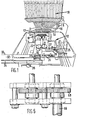
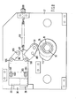
- FIG. 1 there is shown a machine for folding and interleaving fifty sheets of cigarette paper into a so-called booklet, each booklet being separated from adjacent booklets by a strip of cardboard or the like separating material. There are therefore fifty paper strips and a single cardboard strip that have to be fed into the machine from the same number of bobbins.
- These bobbins 10, 11 are arranged in two arcuate rows one above the other and in such a manner that the bobbins 10 in the upper row are in staggered relation to the bobbins 11 in the lower row.
- the arcs of the bobbins 10, 11 are struck from a centre coinciding with the point of convergence of the eventual interleaved paper strip as they enter a drive and cutting unit generally indicated by the reference numeral 12.
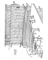
- the paper,leaving bobbins 10, 11 is deflected into a generally horizontal path by upper and lower sets of guide rollers 13, 14 and passes to a first former 15 that is arcuate in plan with its centre coinciding with that of the bobbin arc which folds the several strips.
- the strips pass from the former 15 to a spreading comb 16 that is also arcuate in plan, the purpose of the spreading comb being to spread out and align the folded strips in order to facilitate the first step of interleaving.
- the paper passes from comb 16 to a second former 17 which substantially defines the interfolded shape of the sheets and thence to a final former 18 that serves to bring the interleaving to its final stage and to determine the height of the interleaved booklets.
- Interleaved booklet strand from the guide channel passes between a pair of knurled drive or pull-through rollers 21, 22 both of which are driven through gearing (described below) at a proper surface speed.
- the roller 22 is reci p rocable transversely and is spring loaded into engagement with the advancing strand. The purpose of this arrangement is to maintain a proper pressure on the strand and to compensate for any variation in paper thickness.
- the spring loading enables even a single leaf of paper to be pinched and pulled through, thus simplifying thread up of the complete machine. In earlier machines where the drive or pull through rollers had fixed centres, these were not effective until all the leaves were present between the rollers.
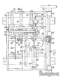
- the strand then enters a cutting unit 25 through an aperture 26 in a leading plate 27 which is closed off by means of a high calibre steel fixed die 30.
- the unit has a trailing plate 28 that is mounted in closely spaced parallel relationship to the plate 27.
- a knife 29 located between the plates 27, 28 has its cutting surface against the inner face of the die 30 and is mounted for shearing movement across the aperture 26 and back to sever booklets from the advancing booklet strand.
- the cutting unit 25 is mounted on linear bearings and is reciprocated by means of a constant velocity cam and follower arrangement so as to move upstream and downstream of the paper strand at the same speed as the paper strand advances.
- the upstream face of the leading plate 27 has a cam operated paper clamping mechanism.
- the strand enters the aperture 26 while the unit 25 is moving upstream of the strand with the clamping mechanism in a disengaged position and with the knife 29 also retracted.
- the travel of the carriage 25 is, of course, half the length of a cut booklet.
- the clamping mechanism closes to hold the booklet strand against the die 30 and during the forward stroke the knife 29 is advanced in appropriately timed relationship to sever a booklet length from the strand.
- the downstream face of the plate carries a pusher mechanism 31 operated by a cam to eject the cut booklet at the downstream extremity of the travel of the unit 25.
- the cut booklets are ejected by the pusher mechanism 31 in a plane normal to the line of advance of the booklet strand onto an endless belt conveyor 32 bounded by upstanding guides 33, 34 to hold the cut booklets in position thereon.
- An indexing mechanism 35 advances the conveyor 32 in booklet thickness increments so that newly cut booklets are accepted onto the conveyor 32 at the proper time.
- a retention bar 36 loaded by leaf springs 37 engages the edge of the last cut booklet as the cutting unit 25 returns so that the advance of the booklet strand into the cutting unit at the next stroke is not impeded by unwanted return of the last cut booklet or part thereof from the conveyor.
- FIG. 3 A general arrangement of the drive unit is shown in Figures 3, 4 and 5. Power from a drive belt of an electric motor is transmitted via pulley wheel 50 to drive input shaft 51 that carries a worm 52 and a hand wheel 53, the shaft being supported for rotation in bearings 54.
- the worm 52 meshes with worm wheel 55 of a transverse shaft 56.
- the shaft 56 carries a helical gear 57 and a sprocket wheel 58.
- a chain 59 connects the sprocket wheel 58 with a further sprocket wheel 60 of a second transverse shaft 61 that drives the constant velocity cam and the pull-through rollers 21, 22.
- Attached to the shaft 61 is a generally heart-shaped cam 62 that provides a uniform motion to a follower assembly including a pair of follower rollers 63 that engage opposite sides of cam 62 and are carried in a uniform cam link 64 that is pivotally connected at 64' to the leading plate 27 of the cutting unit 25.
- the shaft 61 also carries a helical gear 65 that drives a vertical shaft 66 by means of a helical gear 67.
- a straight spur gear 68 (Fig. 6) which in turn drives the two pull-through rollers 21, 22 by a series of interlocking gears.
- the plates 27 and 28 carry four linear bearing carriers 70 that carry pairs of bearing rollers 71 directed at 90 0 that each run on a pair of adjacent faces of rectangular bearing bars 72.
- the location of the bearing carriers 70 can be adjusted to give an accurate alignment of the plates 27, 28.
- the helical gear 57 on the transverse shaft 56 drives a helical drive gear 75 of a shaft 76 of hexagonal section that is supported in a fixed side plate 78 and in end plate 79 with its free end 80 projecting through the plate 79 to provide a drive for the belt conveyor described below.
- the shaft 76 passes through the plates 27, 28 and carries a sleeve 81 of hexagonal core profile and cylindrical external profile which is supported in ball bearings in side plates 27, 28.
- the sleeve 81 carries on the outer face of the plate 27 a cam 82 for operating the clamping mechanism that has a raised lobe 83 that occupies 180° of rotation. Between the plates 27, 28 there is attached to the sleeve 81 a cam 84 that operates the cutting knife. Finally on the outer face of the plate 28 there is attached to the sleeve 81 a third cam 85 that operates the pusher mechanism. It will be noted that the rise of cam 84 occupies only a small angle.
- the clamping mechanism comprises a clamping bar 90 on the outer face of the leading plate 27 and guided for movement towards and away from the aperture 26 by means of straps 91, 91a.
- a tension spring 92 between a pin 93a on the strap 9la nearer the aperture 26 and a pin 93 on the bar 90 urges the clamping bar 90 towards clamping engagement with the interfolded strand of paper entering the aperture 26.
- the bar 90 is lifted from clamping engagement therewith by a link 94 pivoted to the plate 27 and to the bar 90 at pivots 95, 96 and having a follower roller 97 engaged with the cam 82 so that the bar 90 is lifted from engagement with the advancing interfolded strand while the follower roller 97 is on the raised sector 83.
- this is timed to be when the cutting unit 25 is in the return half of its travel.
- the knife 29 is held against the inner face of plate 27 by means of upper and lower studs that locate in oval slots to permit the knife 29 to travel towards and away from the slot 26.
- An upper link 104 is pivoted between the knife 29 and plate 27 at pivots 105, 106.
- a lower link is pivoted at 108, 109 between the knife 29 and the plate 27, the pivots 108, 109 defining a link parallel to the link 104.
- the link 107 is connected to tension spring that returns the knife away from the aperture 26 and also carries a follower roller 111 that engages raised sector 112 on the cam 84 to advance the knife 29 across the aperture 26, thereby severing the strand of interfolded papers that have passed therethrough.
- the motion of the blade has components both towards and across the strand. It will be noted that the follower engages lobe 112 when follower 97 is free from sector 83 so that the cutting is timed to take place when the cutting unit is advancing with the interfolded paper strip clamped in position relative thereto.
- the pusher mechanism which is on the outer face of the trailing plate 28 is shown in Figure 9.
- the pusher 31 is carried by a bar 120 supported in straps 121, 122 for movement transversely of the interfolded paper strand and is urged away therefrom by tension spring between pin 124 on the bar 120 and pin 125 on the plate 28.
- An actuating lever 126 is pivoted to the plate 28 at 127 and to the bar 120 at 128 and carries a follower roller 129 that engages the cam 85.
- the roller 129 traverses lobe 130 on cam 85 to advance the pusher mechanism when the cutting unit 25 reaches the forward end of its travel, so that the cut strand is ejected onto the conveyor 32.
- the free end 80 of the shaft 79 carries an eccentric pivoted to one end of link 140 whose oscillations are transmitted to one end of rachet lever 141 whose other end 142 carries a pawl 143 that engages a toothed drive wheel 144.
- the drive wheel 144 is connected to the shaft of a roller 145, which is one of a pair 145, 146 that support the endless belt conveyor 32.
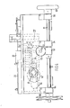
- FIGS 12 and 13 show an alternative embodiment of the cutting unit and take the place of Figure 8 above.
- a knife support 150 rotates in recess 151 in the inner face of leading plate 27 and is supported for rotation between the plates 27, 28 by stub shafts 152, 153 that are supported in rolling contact bearings 154, 155.
- the support 150 rotatably carries a knife 156 having a generally crescent-shaped cutting blade 157 that traverses the aperture 26 once per rotation of the support.
- the blade 157 not only compresses the paper strip during cutting but also moves across it, thereby giving a highly effective cutting action with reduced cutting force required.
- the knife 156 is held to the support 150 by means of a clamping disc 158 which is held in place by a nut 159.
- the support 150 is rotated by means of drive gear 160 that is rotated by driven gear 161 which is rotated by the hexagonal shaft 76.
- the timing of the knife traverse of the aperture 26 is as described with reference to Figure 8.
- the arrangement described has the advantage that it gives a better cutting action, uses only rotating parts rather than reciprocating parts and is constructionally simpler than the arrangement of Figure 8.
- the blade 157 may be arranged to traverse a sharpening stone at each revolution so that it is maintained sharp in service and only has to be replaced at infrequent intervals.
Landscapes
- Folding Of Thin Sheet-Like Materials, Special Discharging Devices, And Others (AREA)
- Diaphragms For Electromechanical Transducers (AREA)
- Measurement Of The Respiration, Hearing Ability, Form, And Blood Characteristics Of Living Organisms (AREA)
- Prostheses (AREA)
- External Artificial Organs (AREA)
- Laminated Bodies (AREA)
- Auxiliary Devices For And Details Of Packaging Control (AREA)
- Credit Cards Or The Like (AREA)
- Paper (AREA)
- Non-Silver Salt Photosensitive Materials And Non-Silver Salt Photography (AREA)
- Manufacturing Of Cigar And Cigarette Tobacco (AREA)
Priority Applications (1)
| Application Number | Priority Date | Filing Date | Title |
|---|---|---|---|
| AT85304051T ATE95504T1 (de) | 1984-06-20 | 1985-06-07 | Maschine zur herstellung von kleinen papierheften. |
Applications Claiming Priority (2)
| Application Number | Priority Date | Filing Date | Title |
|---|---|---|---|
| GB08415758A GB2160511B (en) | 1984-06-20 | 1984-06-20 | Machine for making paper booklets |
| GB8415758 | 1984-06-20 |
Publications (2)
| Publication Number | Publication Date |
|---|---|
| EP0165747A1 true EP0165747A1 (de) | 1985-12-27 |
| EP0165747B1 EP0165747B1 (de) | 1993-10-06 |
Family
ID=10562724
Family Applications (1)
| Application Number | Title | Priority Date | Filing Date |
|---|---|---|---|
| EP85304051A Expired - Lifetime EP0165747B1 (de) | 1984-06-20 | 1985-06-07 | Maschine zur Herstellung von kleinen Papierheften |
Country Status (14)
| Country | Link |
|---|---|
| US (1) | US4648862A (de) |
| EP (1) | EP0165747B1 (de) |
| JP (1) | JPS6163453A (de) |
| AT (1) | ATE95504T1 (de) |
| AU (1) | AU573848B2 (de) |
| BR (1) | BR8502922A (de) |
| CA (1) | CA1239157A (de) |
| DE (1) | DE3587611T2 (de) |
| DK (1) | DK259985A (de) |
| ES (1) | ES8607873A1 (de) |
| FI (1) | FI81553C (de) |
| GB (1) | GB2160511B (de) |
| NO (1) | NO164409C (de) |
| NZ (1) | NZ212438A (de) |
Families Citing this family (4)
| Publication number | Priority date | Publication date | Assignee | Title |
|---|---|---|---|---|
| US5701399A (en) * | 1993-06-09 | 1997-12-23 | Inference Corporation | Integration of case-based search engine into help database |
| DE20200650U1 (de) * | 2002-01-17 | 2003-06-05 | GIZEH Raucherbedarf GmbH, 51647 Gummersbach | Anlage zur Herstellung von Zigarettenpapierbücheln |
| ES2581882T3 (es) * | 2013-07-03 | 2016-09-08 | Imperial Tobacco Limited | Dispositivo para manipular tiras de papel y máquina para producir librillos de hojas de papel |
| CN112590359B (zh) * | 2020-12-29 | 2022-09-27 | 佛山赛元自动化设备有限公司 | 一种侧裁式人造石英石板剥纸装置 |
Citations (4)
| Publication number | Priority date | Publication date | Assignee | Title |
|---|---|---|---|---|
| DE427701C (de) * | 1923-02-20 | 1926-04-15 | Muenchen Kommanditgesellschaft | Maschine zur Herstellung wechselseitig gefalteter und ineinandergelegter Papierblaetter |
| DE2448541A1 (de) * | 1973-10-12 | 1975-04-17 | Chamberlain Phipps Ltd | Faltvorrichtung fuer materialbahnen |
| GB2008282A (en) * | 1977-10-07 | 1979-05-31 | Fuji Photo Film Co Ltd | Method and apparatus for cutting a web ino a specified length |
| GB2065080A (en) * | 1979-12-06 | 1981-06-24 | Kastner A | Process and apparatus for paper interleaving and severing |
Family Cites Families (3)
| Publication number | Priority date | Publication date | Assignee | Title |
|---|---|---|---|---|
| US2414906A (en) * | 1944-09-15 | 1947-01-28 | Taylor Winfield Corp | Sheet feeding and notching |
| US3686989A (en) * | 1970-11-25 | 1972-08-29 | Gen Cigar Co | Quick-return severing device for a moving continuous rod |
| JPS5837090B2 (ja) * | 1979-10-11 | 1983-08-13 | 祥一 佐々木 | 管材切断装置 |
-
1984
- 1984-06-20 GB GB08415758A patent/GB2160511B/en not_active Expired
-
1985
- 1985-06-07 AT AT85304051T patent/ATE95504T1/de not_active IP Right Cessation
- 1985-06-07 DE DE85304051T patent/DE3587611T2/de not_active Expired - Fee Related
- 1985-06-07 EP EP85304051A patent/EP0165747B1/de not_active Expired - Lifetime
- 1985-06-11 DK DK259985A patent/DK259985A/da not_active Application Discontinuation
- 1985-06-17 NZ NZ212438A patent/NZ212438A/en unknown
- 1985-06-17 US US06/745,128 patent/US4648862A/en not_active Expired - Fee Related
- 1985-06-17 CA CA000484220A patent/CA1239157A/en not_active Expired
- 1985-06-17 AU AU43730/85A patent/AU573848B2/en not_active Ceased
- 1985-06-18 BR BR8502922A patent/BR8502922A/pt not_active IP Right Cessation
- 1985-06-19 ES ES544347A patent/ES8607873A1/es not_active Expired
- 1985-06-19 NO NO852473A patent/NO164409C/no unknown
- 1985-06-19 JP JP60132107A patent/JPS6163453A/ja active Granted
- 1985-06-20 FI FI852462A patent/FI81553C/fi not_active IP Right Cessation
Patent Citations (4)
| Publication number | Priority date | Publication date | Assignee | Title |
|---|---|---|---|---|
| DE427701C (de) * | 1923-02-20 | 1926-04-15 | Muenchen Kommanditgesellschaft | Maschine zur Herstellung wechselseitig gefalteter und ineinandergelegter Papierblaetter |
| DE2448541A1 (de) * | 1973-10-12 | 1975-04-17 | Chamberlain Phipps Ltd | Faltvorrichtung fuer materialbahnen |
| GB2008282A (en) * | 1977-10-07 | 1979-05-31 | Fuji Photo Film Co Ltd | Method and apparatus for cutting a web ino a specified length |
| GB2065080A (en) * | 1979-12-06 | 1981-06-24 | Kastner A | Process and apparatus for paper interleaving and severing |
Also Published As
| Publication number | Publication date |
|---|---|
| FI852462A0 (fi) | 1985-06-20 |
| ES544347A0 (es) | 1986-06-01 |
| FI81553C (fi) | 1990-11-12 |
| DE3587611D1 (de) | 1993-11-11 |
| JPS6163453A (ja) | 1986-04-01 |
| GB8415758D0 (en) | 1984-07-25 |
| US4648862A (en) | 1987-03-10 |
| DE3587611T2 (de) | 1994-02-10 |
| NO164409B (no) | 1990-06-25 |
| EP0165747B1 (de) | 1993-10-06 |
| CA1239157A (en) | 1988-07-12 |
| AU573848B2 (en) | 1988-06-23 |
| FI852462L (fi) | 1985-12-21 |
| DK259985A (da) | 1985-12-21 |
| ES8607873A1 (es) | 1986-06-01 |
| FI81553B (fi) | 1990-07-31 |
| JPH0548744B2 (de) | 1993-07-22 |
| NO164409C (no) | 1990-10-03 |
| GB2160511B (en) | 1987-11-18 |
| NO852473L (no) | 1985-12-23 |
| BR8502922A (pt) | 1986-03-04 |
| GB2160511A (en) | 1985-12-24 |
| AU4373085A (en) | 1986-01-02 |
| ATE95504T1 (de) | 1993-10-15 |
| NZ212438A (en) | 1987-09-30 |
| DK259985D0 (da) | 1985-06-11 |
Similar Documents
| Publication | Publication Date | Title |
|---|---|---|
| DE69016067T2 (de) | Verfahren und Vorrichtung zum Bilden eines neuen Stapels nach dem Abnehmen von einem fertigen Stapel, in einer, insbesondere einem Printer zugeordneten, Stapelbildungsmaschine. | |
| US3973373A (en) | Automatic packaging method and apparatus | |
| US3984272A (en) | Method and apparatus for successively forming disposable diapers | |
| US4775358A (en) | Machine for making paper booklets | |
| US5090672A (en) | Automatic apparatus for folding sheet elements | |
| DE3043507C2 (de) | ||
| DE2137751A1 (de) | Vorrichtung zur Herstellung von Zigarettenhülsen | |
| US4386924A (en) | Handle bag making apparatus | |
| US4648862A (en) | Machine for making paper booklets | |
| US2776610A (en) | Cutting and creasing press | |
| EP0174386B1 (de) | Vorrichtung zum Falten von Bahnen | |
| EP0333634B1 (de) | Vorrichtung zur Herstellung von Münzenrollen | |
| US4986864A (en) | Page binding method and machine | |
| US6858109B2 (en) | Segment cut honeycomb core machine | |
| EP2559549A1 (de) | Vorrichtung und Verfahren zum Bearbeiten von Bogen aus Papier oder einem anderen flexiblen Material | |
| EP0272048B1 (de) | Maschine zum Herstellen von Papierblöcken | |
| DE3534919C2 (de) | ||
| US3752469A (en) | Folding machine and method of pressing a fold | |
| US2059960A (en) | Machine for compressing and loading articles of flat form | |
| US2012561A (en) | Severing and collating means | |
| US4603533A (en) | Apparatus for manufacturing discrete layered units from a web | |
| DE3515655A1 (de) | Verfahren und vorrichtung zum umhuellen von packungen mit huellmaterial | |
| EP0077843A1 (de) | Vorrichtung zum Herstellen von Tragtaschen | |
| DE276883C (de) | Maschine zur Herstellung con Züundhölzern in flachen Packungen in fortlaufendem Arbeitsgang | |
| US1802357A (en) | Lug-folding machine |
Legal Events
| Date | Code | Title | Description |
|---|---|---|---|
| PUAI | Public reference made under article 153(3) epc to a published international application that has entered the european phase |
Free format text: ORIGINAL CODE: 0009012 |
|
| AK | Designated contracting states |
Designated state(s): AT BE CH DE FR IT LI LU NL SE |
|
| 17P | Request for examination filed |
Effective date: 19860509 |
|
| 17Q | First examination report despatched |
Effective date: 19861222 |
|
| 19A | Proceedings stayed before grant |
Effective date: 19880111 |
|
| REG | Reference to a national code |
Ref country code: GB Ref legal event code: 712C |
|
| REG | Reference to a national code |
Ref country code: GB Ref legal event code: 712C |
|
| 19F | Resumption of proceedings before grant (after stay of proceedings) |
Effective date: 19911021 |
|
| REG | Reference to a national code |
Ref country code: GB Ref legal event code: 712C |
|
| ITF | It: translation for a ep patent filed | ||
| GRAA | (expected) grant |
Free format text: ORIGINAL CODE: 0009210 |
|
| AK | Designated contracting states |
Kind code of ref document: B1 Designated state(s): AT BE CH DE FR IT LI LU NL SE |
|
| REF | Corresponds to: |
Ref document number: 95504 Country of ref document: AT Date of ref document: 19931015 Kind code of ref document: T |
|
| REF | Corresponds to: |
Ref document number: 3587611 Country of ref document: DE Date of ref document: 19931111 |
|
| ET | Fr: translation filed | ||
| PG25 | Lapsed in a contracting state [announced via postgrant information from national office to epo] |
Ref country code: LU Free format text: LAPSE BECAUSE OF NON-PAYMENT OF DUE FEES Effective date: 19940630 |
|
| PLBE | No opposition filed within time limit |
Free format text: ORIGINAL CODE: 0009261 |
|
| STAA | Information on the status of an ep patent application or granted ep patent |
Free format text: STATUS: NO OPPOSITION FILED WITHIN TIME LIMIT |
|
| 26N | No opposition filed | ||
| EAL | Se: european patent in force in sweden |
Ref document number: 85304051.7 |
|
| PGFP | Annual fee paid to national office [announced via postgrant information from national office to epo] |
Ref country code: FR Payment date: 19960610 Year of fee payment: 12 |
|
| PGFP | Annual fee paid to national office [announced via postgrant information from national office to epo] |
Ref country code: SE Payment date: 19960614 Year of fee payment: 12 Ref country code: AT Payment date: 19960614 Year of fee payment: 12 |
|
| PGFP | Annual fee paid to national office [announced via postgrant information from national office to epo] |
Ref country code: NL Payment date: 19960620 Year of fee payment: 12 |
|
| PGFP | Annual fee paid to national office [announced via postgrant information from national office to epo] |
Ref country code: BE Payment date: 19960624 Year of fee payment: 12 |
|
| PGFP | Annual fee paid to national office [announced via postgrant information from national office to epo] |
Ref country code: DE Payment date: 19960626 Year of fee payment: 12 |
|
| PGFP | Annual fee paid to national office [announced via postgrant information from national office to epo] |
Ref country code: CH Payment date: 19960702 Year of fee payment: 12 |
|
| PG25 | Lapsed in a contracting state [announced via postgrant information from national office to epo] |
Ref country code: AT Effective date: 19970607 |
|
| PG25 | Lapsed in a contracting state [announced via postgrant information from national office to epo] |
Ref country code: SE Effective date: 19970608 |
|
| PG25 | Lapsed in a contracting state [announced via postgrant information from national office to epo] |
Ref country code: LI Free format text: LAPSE BECAUSE OF NON-PAYMENT OF DUE FEES Effective date: 19970630 Ref country code: CH Free format text: LAPSE BECAUSE OF NON-PAYMENT OF DUE FEES Effective date: 19970630 Ref country code: BE Effective date: 19970630 |
|
| BERE | Be: lapsed |
Owner name: RIZLA LTD Effective date: 19970630 |
|
| PG25 | Lapsed in a contracting state [announced via postgrant information from national office to epo] |
Ref country code: NL Effective date: 19980101 |
|
| REG | Reference to a national code |
Ref country code: CH Ref legal event code: PL |
|
| PG25 | Lapsed in a contracting state [announced via postgrant information from national office to epo] |
Ref country code: FR Free format text: LAPSE BECAUSE OF NON-PAYMENT OF DUE FEES Effective date: 19980227 |
|
| EUG | Se: european patent has lapsed |
Ref document number: 85304051.7 |
|
| NLV4 | Nl: lapsed or anulled due to non-payment of the annual fee |
Effective date: 19980101 |
|
| PG25 | Lapsed in a contracting state [announced via postgrant information from national office to epo] |
Ref country code: DE Free format text: LAPSE BECAUSE OF NON-PAYMENT OF DUE FEES Effective date: 19980303 |
|
| REG | Reference to a national code |
Ref country code: FR Ref legal event code: ST |
|
| REG | Reference to a national code |
Ref country code: FR Ref legal event code: ST |