EP0165432A1 - Furnace, especially for the combustion of refuse, coal, wood and industrial waste - Google Patents
Furnace, especially for the combustion of refuse, coal, wood and industrial waste Download PDFInfo
- Publication number
- EP0165432A1 EP0165432A1 EP85105632A EP85105632A EP0165432A1 EP 0165432 A1 EP0165432 A1 EP 0165432A1 EP 85105632 A EP85105632 A EP 85105632A EP 85105632 A EP85105632 A EP 85105632A EP 0165432 A1 EP0165432 A1 EP 0165432A1
- Authority
- EP
- European Patent Office
- Prior art keywords
- grate
- oven
- bars
- air
- preferably according
- Prior art date
- Legal status (The legal status is an assumption and is not a legal conclusion. Google has not performed a legal analysis and makes no representation as to the accuracy of the status listed.)
- Granted
Links
Images


Classifications
-
- F—MECHANICAL ENGINEERING; LIGHTING; HEATING; WEAPONS; BLASTING
- F23—COMBUSTION APPARATUS; COMBUSTION PROCESSES
- F23H—GRATES; CLEANING OR RAKING GRATES
- F23H17/00—Details of grates
-
- F—MECHANICAL ENGINEERING; LIGHTING; HEATING; WEAPONS; BLASTING
- F23—COMBUSTION APPARATUS; COMBUSTION PROCESSES
- F23G—CREMATION FURNACES; CONSUMING WASTE PRODUCTS BY COMBUSTION
- F23G5/00—Incineration of waste; Incinerator constructions; Details, accessories or control therefor
- F23G5/002—Incineration of waste; Incinerator constructions; Details, accessories or control therefor characterised by their grates
-
- F—MECHANICAL ENGINEERING; LIGHTING; HEATING; WEAPONS; BLASTING
- F23—COMBUSTION APPARATUS; COMBUSTION PROCESSES
- F23H—GRATES; CLEANING OR RAKING GRATES
- F23H7/00—Inclined or stepped grates
Definitions
- the present invention relates to a furnace, in particular for the combustion of waste, coal, wood and industrial waste, with grate sloping backwards in stages.
- the pressure drop in the combustion air lies in the grate or grate covering and not in the combustion material. Air pressure builds up under the grate. The combustion air only flows into the medium to be burned through recesses, holes or slots in the grate. It is less important whether there is good or poorly flammable material on the grate.
- a device for compensating dimensional changes in components caused by temperature fluctuations in particular in the case of a grate or an input device for furnaces, which has at least one displacement direction of a component which is movable in the direction of a compensation of the temperature fluctuations and must be compensated for and against this Component has a cheek that can be pressed by means of an adjusting device.
- the cheek is swinging and open Bearing provided, which are movable in the direction of the displacement movement of the component or components to be compensated.
- CH-PS 619 764 this construction is quite expensive to carry out and its moving parts are more prone to failure than if no such moving parts were provided.
- Another construction discloses a feed grate for incinerators, in particular garbage incinerators, with rows of grate blocks which can be moved in the feed direction and run transversely to the grate.
- each transverse row is engaging with one of the two outermost grate blocks this transverse row and the gaps R ostblöcke resiliently pressing to each other the clamping device is provided.
- CH-PS 585 372 This construction is also prone to failure and complicated because of the parts to be moved in rough operation at high temperatures.
- the present invention aims to provide a furnace which avoids temperature-compensating means as externally moved parts and is therefore more suitable in terms of operation and wear than the previously known designs.
- Another object of the invention is to develop a combustion grate system which achieves a very high degree of efficiency with simple means, can be produced and operated inexpensively.
- such a furnace is characterized in that the grate forms a sealing closure on at least one side with the combustion chamber, which allows the grate to be freely expanded and contracted as a result of temperature influences.
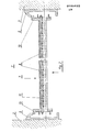
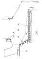
- a side delimitation of a furnace 1 of a furnace - it can also be a boiler - for the incineration of waste, coal, wood and industrial waste is indicated with two brick side walls 2 and 3.
- a steel structure with two fixed sealing rails 5 and 5 and 6 can be seen.
- a sliding grate 7 is shown schematically. It is composed of grate bars 8, as shown in FIGS. 5 to 7. End profiles 10 can be seen on the side of the grate.
- a plurality of tie rods 11 distributed over the grate width each combine grate rod packs or blocks to connect them.
- the sealing profiles 13 matching the rails 5 and 6 can be seen.
- left and right elements are attached to the sealing profiles 13 on the end grate bars of the fixed grate bar rows on the end grate bars of the fixed grate bar rows, which are usual with feed grates.
- These profiles 13 are connected to the fixed grate bars 8. If necessary, they can still be supported on the solid grating supports.
- the grating that is held together in this way can expand and contract with the thermal expansion to the left and right without problems and without lateral pressure or tension.
- the side rails 5 and 6 ensure expansion absorption and controlled air outlet. i
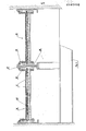
- a construction with side closure of the grate 7 in which the sealing rails 5 and 6 are not direct r are attached to the masonry side walls 2 and 3, but via brackets 20.
- the substructure to the grate 7 with cross members 21 and 22 is also shown.
- additional grate bars 24 arranged laterally at an angle are introduced, which are held on a holding rail 26 fastened to the steel structure with the aid of the support arms 27 and 28.
- These are also grate bars, as can be seen in detail in FIGS. 5 to 7.
- a support bracket 29 is arranged in the middle of the rod 24.
- the ash funnel 30 lies below the grate 7.
- Fig. 3 shows a further, even better developed construction of the one side to a combustion chamber 1, in which construction above the inclined side grate bars 24 to produce a trough-like grate fixed sloping and side walls, defined by the grate bars 24, 'and grate bars 32nd are arranged, the grate bar 32 in turn corresponds to a construction as shown in FIGS. 5 to 7 in detail.
- the side-by-side grate bars 32 are held by corresponding supports 33, since these bars 34 and 35 are inserted with play, as explained later.
- FIGS. 1 and 3 show how the grate can be enlarged laterally in a simple manner by obliquely arranged grate bars 24 and expanded like a trough by means of grate bars 32 additionally arranged above it, which contributes to a substantial increase in capacity of an existing oven.
- the grate bars 24 and 32 together with their end boundaries, define air outlet channels, as indicated by corresponding arrows.
- a side end piece can be used.
- the grate surface is enlarged simply and inexpensively by this rust broadening and the dreaded edge fire is also eliminated. This is made possible by the optional air outlet openings that keep the fire away from the side walls.
- the rising gases are mixed with secondary air and burned out.
- the air is blown back from the combustion chamber walls into the hot core zone by the air blown in in two directions.
- Through the air curtain placed in front of the boiler pipes or the masonry the radiant heat of the combustion chamber is partially suppressed.
- the heat of the ceramic walls or the masonry, which is still absorbed by radiation, is reflected in the combustion chamber.
- grate systems There are installation options for a wide variety of grate systems. As an extension and optimization of the aforementioned grate system or individually in existing plants and systems, one or more grate bars can be attached. The air volumes can be selected via column 14 to be determined.
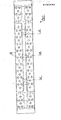
- FIG. 4 shows a construction of a very wide combustion chamber with a wide grate 36 which is divided into two parts by means of a central web 37.
- This wide grate 36 is sealed in the middle with the aid of sealing rails 38 and sealing profiles 39 in the manner discussed, but allows the two grate parts to move freely to the side in the event of temperature fluctuations in the combustion chamber.
- cup springs 40 between the individual grate bars in order to achieve a tie rod effect in this way, i.e. to ensure a corresponding elastic behavior of the grate in the transverse direction.
- the wide grate 36 has the same structure and can be supplemented as well as the grids shown in FIGS. 1 to 3.
- a turning grate bar 8 can be seen, as this is preferably used for the grids described above.
- This rod 8 has a T-shaped cross section 41, as can be seen in the section plane VII - VII in FIG. 7.
- the grate bars 8 since they are so-called turning grate bars, are designed symmetrically with respect to the transverse median plane, which allows them to be rotated through 180 °, e.g. by turning about their polar axis (parallel to the cutting axis VII - VII in the median plane). if burning has occurred, turn the front part.
- semicircular support shells 43 and 44 are formed, the diameter of which is larger in the horizontal direction than in the vertical, so that there is a longitudinal play of the grate bar 8 used with respect to the holding axis, a measure which prevents any jamming.
- a cleaning stroke will take place due to the forward and backward movement of the moving rods with the frictional resistances. Any foreign bodies that may have penetrated from the air gaps may fail due to the shifting of the grate bar.
- the storage takes place in the rear part of the grate bar 8, i.e. in the support shell 43 e.g.
- Corresponding transverse walls 46 are provided in the area of the bearing shells 43 and 44 for reinforcement. Lateral oval passages 47, 48 and 49 allow the assembly of grate bars 8 lying next to one another in the form of groups, which in turn are combined to form the overall grate.
- the cooling pins 50 are additionally provided with conical lower parts 51 with a smaller diameter, with shoulders serving to support duct plate profiles 52 and 53 at the transition point of the cooling pins 50 into the lower parts 51, which profiles also, as shown in FIG. 7 shows are attached laterally in the T-shaped main part. Not shown, but possible is the same arrangement for the front and rear part of the grate bar.
- each grate bar 8 are each provided with an air nozzle 54 or 55, which is inclined upwards, ie at an angle to the support surface 42, one Straighten the air jet, which does not aim at the contact surface 42 of the grate bar 8 in front of it and thus protects it from excessive surface temperatures as a result of fanned combustion. It is worth noting the targeted air outlet of the side wall nozzles on the turning grate bars, which aim into the combustion bed and do not flow against the grate bars. This avoids excessive heating of the grate bars. There are no metal melts caused by local overheating, which disrupt operational safety and the service life of the grate bars due to excessive Reduce wear.
- the air nozzles 54 and 55 as can be seen, converge towards the nozzle mouth, whereby an accelerated air flow is generated in the nozzle.
- the turbulence of this air jet is improved in that the nozzle guide walls are designed like a confuser and not parallel walls.
- the cooling air passes through the rear air nozzle 54 into the space 58 in the region of the upper pins 50, which, as shown, is preferably closed by means of the duct plate profiles 52 and 53 in such a way that the air flow brings optimal heat transfers to the cooling pins arranged in staggered rows.
- the lower parts 51 of the cooling pins 50 also allow the heat-emitting surfaces to be enlarged.
- Through bores 56 and 57 in the transverse walls 46 result in the continuous air duct informing the space 58 from the air nozzle 54 to the air nozzle 55.
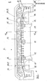
- FIG. 8 shows a combustion chamber 60 in longitudinal section with respect to the grate, with a feed plunger 61 and an inclined grate 62 assembled from fixed grate bars 8 and a subsequent combustion grate 63.
- the firing material coming from the feed plunger 61, arrives, as shown by reference number 65. onto the sloping grate 62 and slips on the incineration grate 63 in order to then fall into the slag shaft 67 completely burned out as slag material.
- This construction allows using an oblique grate 62 to significantly improve the combustion of the combustible material and prevents premature 'dropping of the not yet completely burnt material over so-called. Rust falls into the slag pit 67th
- So-called rust falls are installed in incineration plants and especially in waste incineration plants. These have the task of loosening and rearranging the combustion material when it falls.
- the intention here is to replace these lintels with the slanted gratings 62.
- This helps to avoid deflagrations and fluctuations in operation during the dropping process.
- the grate area is enlarged and the burnout section is extended.
- These inclined gratings 62 can be designed to be stationary or movable. Problems of rust falls with the slag caking, high wear and tear and training with cooling plates and their air requirement are thus eliminated.
- a built-in sloping grate 62 in a waste incineration plant increases the active grate area significantly and produces very good results through increased performance and good burn-out. The position of the grate bars results in a loosening of the waste in this case with a targeted air entry into the combustion material.
- the illustration according to FIG. 8 also shows how the grate bars 8 are arranged on the supports of the substructure of the grates on corresponding supports or axles and each rest on the upstream rows of grate bars with the front part.
- the odd grate bar rows are fixed components of the grate, while the straight grate bar rows in FIG ter way by pushing back and forth of the carrier profiles with their front parts, the accumulated on the following fixed grate bar row 65, in which way the well 65 is known to be moved in the direction of the slag shaft 67 forward.
Abstract
Description
Die vorliegende Erfindung betrifft einen Ofen, insbesondere zur Verbrennung von Müll, Kohle, Holz und Industrieabfällen, mit in Stufen nach hinten abfallendem Rost.The present invention relates to a furnace, in particular for the combustion of waste, coal, wood and industrial waste, with grate sloping backwards in stages.
In Müllverbrennungsanlagen werden verschiedene Verbrennungsroste eingesetzt. Speziell grössere Anlagen arbeiten mit gespannten oder gepressten Rosten. Dies ist leicht erklärlich, wenn man den Verbrennungsablauf betrachtet. Bei nicht gespannten oder nicht gepressten Rosten werden üblicherweise Roststäbe oder Rostblöcke verwendet, welche seitlich ein Dehnungsspiel haben. Dieses Dehnungsspiel ist über die gesamte Rostbreite, zum Teil ungleichmässig,verteilt. An den Seiten zu den Feuerraumwänden besteht ebenfalls ein Luftspalt als Dehnungsspiel. Bei diesen bekannten Rosten liegt der Druckabfall der Verbrennungsluft, gegeben durch die Luftspalte, grösstenteils im Verbrennungsgut.Various incineration grates are used in waste incineration plants. Larger systems in particular work with tensioned or pressed grates. This is easy to explain when you look at the combustion process. For grids that are not tensioned or not pressed, grate bars or grate blocks are usually used, which have an expansion play on the side. This expansion play is distributed across the entire grate width, sometimes unevenly. There is also an air gap on the sides of the combustion chamber walls as an expansion game. In these known grates, the pressure drop in the combustion air, given by the air gaps, is largely in the combustion material.
Auch bei der Verbrennung lässt sich beobachten, dass die Verbrennungsluft immer den Weg des geringsten Widerstandes geht. Liegt z.B. auf einer Rostseite Papier (hoher Heizwert), so brennt dies sofort ab. Auf der anderen Rostseite liegende Gemüseabfälle (tiefer Heizwert) brennen nicht. Durch das verbrannte Papier entsteht ein Loch im Verbrennungsgut, durch welches die Verbrennungsluft, ohne nennenswerten Widerstand, praktisch nutzlos entweicht. Die zur Verbrennung der Gemüseabfälle (tiefer Heizwert) notwendige Luft entweicht durch das Papierloch und fehlt für die Verbrennung der Bestandteile mit tiefem Heizwert. Somit entsteht ein mangelhafter Ausbrand.When it comes to combustion, too, it can be observed that the combustion air always follows the path of least resistance. For example, if there is paper on a grate side (high calorific value), this burns off immediately. Vegetable waste on the other grate side (low calorific value) does not burn. The burnt paper creates a hole in the combustion material, through which the combustion air escapes uselessly without any significant resistance. The ones for burning the vegetables Waste (low calorific value) necessary air escapes through the paper hole and is missing for the combustion of the components with low calorific value. This results in poor burnout.
Bei gespannten oder gepressten Rosten liegt der Druckabfall der Verbrennungsluft im Rost bzw. Rostbelag und nicht im Verbrennungsgut. Unter dem Rostbelag baut sich ein Luftdruck auf. Die Verbrennungsluft strömt nur durch Ausnehmungen, Löcher oder Schlitze im Rostbelag in das zu verbrennende Medium. Dabei ist es weniger bedeutend, ob auf dem Rost gut oder schlecht brennbares Material liegt.In the case of tensioned or pressed grates, the pressure drop in the combustion air lies in the grate or grate covering and not in the combustion material. Air pressure builds up under the grate. The combustion air only flows into the medium to be burned through recesses, holes or slots in the grate. It is less important whether there is good or poorly flammable material on the grate.
Gegeben durch den höheren Widerstand im Rostbelag als im Verbrennungsgut tritt überall gleichmässig die Verbrennungsluft auf das zu verbrennende Material. Die Folge ist ein guter, gleichmässiger Ausbrand des Verbrennungsgutes. Erreicht wird dieses Resultat mit mehr oder minder grossem Aufwand und Verschleiss an Teilen.Due to the higher resistance in the grate than in the material to be burned, the combustion air appears evenly on the material to be burned. The result is a good, even burnout of the combustion material. This result is achieved with more or less great effort and wear on parts.
In diesem Sinne ist beispielsweise eine Einrichtung zur Kompensation von durch Temperaturschwankungen hervorgerufenen Dimensionsänderungen bei Bauteilen, insbesondere bei einem Rost oder einer Eingabevorrichtung bei Feuerungen, bekannt geworden, welche zumindest eine in der Richtung einer durch die Temperaturschwankungen bedingten und auszugleichenden Verschieberichtung eines Bauteils bewegbare und gegen diesen Bauteil mittels einer Nachstellvorrichtung drückbare Wange aufweist. Dabei ist die Wange pendelnd gelagert und Auflager vorgesehen, die in der Richtung der auszugleichenden Verschiebebewegung des Bauteils bzw. der Bauteile bewegbar sind. (CH-PS 619 764) Diese Konstruktion ist aber in ihrer Ausführung recht kostspielig und mit ihren bewegten Teilen störanfälliger, als wenn keine derartigen bewegten Teile vorgesehen werden.In this sense, for example, a device for compensating dimensional changes in components caused by temperature fluctuations, in particular in the case of a grate or an input device for furnaces, has become known which has at least one displacement direction of a component which is movable in the direction of a compensation of the temperature fluctuations and must be compensated for and against this Component has a cheek that can be pressed by means of an adjusting device. The cheek is swinging and open Bearing provided, which are movable in the direction of the displacement movement of the component or components to be compensated. (CH-PS 619 764) However, this construction is quite expensive to carry out and its moving parts are more prone to failure than if no such moving parts were provided.
Eine andere Konstruktion offenbart einen Vorschubrost für Verbrennungsöfen, insbesondere Müllverbrennungsöfen, mit quer zum Rost verlaufenden Reihen von in Vorschubrichtung bewegbaren Rostblöcken. Bei diesem Rost ist jede Blockquerreihe mit einer an einem der beiden äussersten Rostblöcke dieser Querreihe angreifenden und deren Rostblöcke lückenlos federnd aneinander drückenden Spannvorrichtung vorgesehen. (CH-PS 585 372) Auch diese Konstruktion ist wegen der zu bewegenden Teile im groben Betrieb bei hohen Temperaturen störanfällig und kompliziert.Another construction discloses a feed grate for incinerators, in particular garbage incinerators, with rows of grate blocks which can be moved in the feed direction and run transversely to the grate. In this grate block, each transverse row is engaging with one of the two outermost grate blocks this transverse row and the gaps R ostblöcke resiliently pressing to each other the clamping device is provided. (CH-PS 585 372) This construction is also prone to failure and complicated because of the parts to be moved in rough operation at high temperatures.
Die vorliegende Erfindung bezweckt die Schaffung eines Ofens, welcher temperaturausgleichende Mittel als fremdbewegte Teile vermeidet und damit bezüglich Betrieb und Verschleiss sich besser eignet als die bisher bekannt gewordenen Ausführungen.The present invention aims to provide a furnace which avoids temperature-compensating means as externally moved parts and is therefore more suitable in terms of operation and wear than the previously known designs.
Ein Ziel der Erfindung besteht ferner darin, ein Verbrennungsrostsystem zu entwickeln, welches mit einfachen Mitteln einen sehr hohen Wirkungsgrad erreicht, kostengünstig zu erstellen und zu betreiben ist.Another object of the invention is to develop a combustion grate system which achieves a very high degree of efficiency with simple means, can be produced and operated inexpensively.
Diesem Zweck dienen entsprechend ausgebildete Roststäbe sowie eingebaute, die Roststäbe federnd wirkverbindende Elemente.Correspondingly designed grate bars and built-in elements which connect the grate bars in a resilient manner serve this purpose.
Ein derartiger Ofen zeichnet sich erfindungsgemäss dadurch aus, dass der Rost mindestens auf einer Seite mit dem Feuerraum einen dichtenden Abschluss bildet, welcher ein freies seitliches Dehnen und Zusammenziehen des Rostes infolge Temperatureinflüssen erlaubt.According to the invention, such a furnace is characterized in that the grate forms a sealing closure on at least one side with the combustion chamber, which allows the grate to be freely expanded and contracted as a result of temperature influences.
Im weiteren sind auch die Inhalte der übrigen Ansprüche allesamt erfindungswesentlich.Furthermore, the contents of the remaining claims are all essential to the invention.
Die Erfindung wird anschliessend beispielsweise anhand einer Zeichnung erläutert.The invention is subsequently explained, for example, using a drawing.
Es zeigen:
- Fig. 1 einen Querschnitt durch den Feuerraum eines Ofens zur Verbrennung von Müll, Kohle, Holz und Industrieabfällen,
- Fig. 2 einen Ausschnitt aus Fig. 1 einer ähnlichen Rostanlage gemäss Fig. 1,
- Fig. 3 eine Einzelheit aus einer Variante eines Feuerraumquerschnittes analog Fig. 1,
- Fig. 4 eine Variante analog Fig. 1 eines sehr breiten Feuerraumes,
- Fig. 5 eine Seitenansicht eines Wechselroststabes,
- Fig. 6 eine Aufsicht auf den Wechselroststab gemäss Fig. 5,
- Fig. 7 einen Schnitt durch den Wechselroststab gemäss Schnittlinie VII - VII der Fig. 5,
- Fig. 8 eine schematische Darstellung eines Ausschnittes aus einem Feuerraum eines Ofens zur Verbrennung von Mull, Kohle, Holz und Industrieabfällen, mit dem Rost in Seitenansicht.
- 1 shows a cross section through the furnace of a furnace for the combustion of waste, coal, wood and industrial waste,
- 2 shows a detail from FIG. 1 of a similar grate system according to FIG. 1,
- Fig. 3 shows a detail from a variant of a combustion chamber cross section analogous to F ig. 1,
- 4 shows a variant analogous to FIG. 1 of a very wide combustion chamber,
- 5 is a side view of an interchangeable grate bar,
- 6 is a plan view of the removable grate bar according to FIG. 5,
- 7 shows a section through the exchangeable grate rod according to section line VII - VII of FIG. 5,
- Fig. 8 is a schematic representation of a section of a furnace of a furnace for the combustion of gauze, coal, wood and industrial waste, with the grate in side view.
Die Seitenbegrenzung eines Feuerraumes 1 eines Ofens - es kann auch ein Heizkessel-sein - zur Verbrennung von Müll, Kohle, Holz und Industrieabfällen ist mit zwei gemauerten Seitenwänden 2 und 3 angedeutet. Im Mauerwerk dieser Seitenwände 2 und 3 ist eine Stahlkonstruktion, mit zwei festen Dichtungsschienen 5 bzw. 5 und 6 ersichtlich. Ein Schieberost 7 ist schematisch dargestellt. Er setzt sich aus Roststäben 8, wie diese in den Fig. 5 bis 7 dargestellt sind, zusammen. Seitlich am Rost sind Abschlussprofile 10 ersichtlich. Mehrere auf die Rostbreite verteilte Zuganker 11 fassen jeweils Roststabpakete oder -Blöcke verbindend zusammen. An den Seiten des Rostes 7 sind die zu den Schienen 5 bzw. 6 passenden Dichtungsprofile 13 ersichtlich. Sie legen jeweils mit den entsprechenden oberen Abschlussflanken der Schienen 5 bzw. 6 Spalte 14 fest, welche so gewählt werden, dass das zu verbrennende Gut nicht seitlich durchtreten kann und auch der Luftdurchtritt geregelt bleibt. Anderseits ermöglicht diese Konstruktion ein freies seitliches Ausdehnen und Zusammenziehen des Rostes 7, ohne dass dazu irgendwelche Klemmvorrichtungen benötigt werden. Dies sichert ein einwandfreies Arbeiten des Rostes zwischen den Seitenwänden 2 und 3, ohne irgendwelche Gefahr des Verklemmens bei den Hin- und Herbewegungen von Roststäben und ohne irgendwelche zusätzlichen mechanischen Betätigungsmittel.The side delimitation of a
Möglich ist die Befestigung der Roststäbe zu Blöcken untereinander mit der berechneten Wärmeausdehnung.It is possible to fasten the grate bars to blocks with one another with the calculated thermal expansion.
An den seitlichen Enden der so gebildeten Rostfläche werden an den bei Vorschubrosten üblichen festen und beweglichen Roststabreihen an den Endroststäben der festen Roststabreihen Links- und Rechtselemente mit Schleissplatten inform der Dichtungprofile 13 befestigt. Diese Profile 13 sind mit den feststehenden Roststäben 8 verbunden. Sie können gegebenenfalls noch auf den festen Rostbelagsträgern abgestützt werden.At the lateral ends of the grate surface formed in this way, left and right elements are attached to the
Der so in sich zusammengehaltene Rostbelag kann sich mit der Wärmeausdehnung nach links und rechts unproblematisch und ohne seitliche Pressung oder Zug ausdehnen und zusammenziehen.The grating that is held together in this way can expand and contract with the thermal expansion to the left and right without problems and without lateral pressure or tension.
Die seitlichen Schienen 5 und 6 gewährleisten die Dehnungsaufnahme und den kontrollierten Luftaustritt. iThe side rails 5 and 6 ensure expansion absorption and controlled air outlet. i
In Fig. 1 ist, im Gegensatz zur Fig. 2, eine Konstruktion mit Seitenabschluss des Rostes 7 dargestellt, bei welcher die Dichtungsschienen 5 und 6 nicht direkt r an den gemauerten Seitenwänden 2 und 3 befestigt sind, sondern über Konsolen 20. Dabei ist auch die Unterkonstruktion zum Rost 7 mit Querträgern 21 und 22 dargestellt. Zur Verbreiterung des Rostes 7 sind hier zusätzliche, seitlich schräg angeordnete Roststäbe 24 eingebracht, welche an einer an der Stahlkonstruktion befestigten Halteschiene 26 mit Hilfe der Tragarme 27 und 28 gehalten sind. Es handelt sich auch hier um Roststäbe, wie solche in Einzelheiten in den Fig. 5 bis 7 ersichtlich sind. In der Mitte des Stabes 24 ist eine Haltestütze 29 angeordnet. Unterhalb des Rostes 7 liegt der Aschentrichter 30.In Fig. 1, in contrast to Fig. 2, a construction with side closure of the
Fig. 3 zeigt eine weitere, noch besser ausgebaute Konstruktion der einen Seite zu einem Feuerraum 1, bei welcher Konstruktion über den schrägen Seitenroststäben 24 zur Erzeugung eines im Querschnitt trogähnlichen Rostes feste Schräg- und Seitenwände, festgelegt durch die Roststäbe 24,'und Roststäbe 32 angeordnet sind, wobei der Roststab 32 wiederum einer Konstruktion entspricht, wie sie die Fig. 5 bis 7 in Einzelheiten zeigt. Die nebeneinander liegenden Seitenroststäbe 32 werden durch entsprechende Stützen 33 gehaltert, da diese Stäbe 34 und 35, wie an späterer Stelle erläutert, mit Spiel eingesetzt sind..Fig. 3 shows a further, even better developed construction of the one side to a
Für solche Roste ist nur ein Modell von Roststäben 8 notwendig. In der Breite lässt sich dieser Typ durch seitliches Abnehmen anpassen, so dass keine Passteile erforderlich sind.Only one model of
Die Konstruktionen gemäss den Fig. 1 und 3 zeigen, wie auf einfache Weise der Rost seitlich durch schräg angeordnete Roststäbe 24 vergrössert und durch darüber zusätzlich angeordnete Roststäbe 32 trogähnlich ausgebaut werden kann, was zu einer wesentlichen Kapazitätserhöhung eines bestehenden Ofens beiträgt. Die Roststäbe 24 und 32 legen zusammen mit ihren Endbegrenzungen Luftaustrittskanäle fest, wie entsprechende Pfeile es andeuten.The constructions according to FIGS. 1 and 3 show how the grate can be enlarged laterally in a simple manner by obliquely arranged grate bars 24 and expanded like a trough by means of grate bars 32 additionally arranged above it, which contributes to a substantial increase in capacity of an existing oven. The grate bars 24 and 32, together with their end boundaries, define air outlet channels, as indicated by corresponding arrows.
Dies zeigt damit eine einfache Möglichkeit, bei losen oder gebundenen und gepressten Rosten die Rostverbreiterung durch das Anfügen eines Roststabes, welcher in der Stellung O° bis erwünschte Schräge oder Senkrechte eingebaut wird. Bei ungepressten Rosten kann der Einbau fix erfolgen, ebenfalls bei gehalterten Rosten.This shows a simple way of broadening the grate in the case of loose or bound and pressed grates by adding a grate bar, which is installed in the 0 ° position to the desired incline or perpendicular. In the case of unpressed gratings, the installation can be fixed, also in the case of supported grates.
Wie beim gepressten Rost, kann ein seitliches Abschlussstück verwendet werden. Die Rostfläche ist durch diese Rostverbreiterung einfach und kostengünstig vergrössert und zudem ist die gefürchtete Randfeuerbildung eliminiert. Dies wird ermöglicht durch die in der Grösse wahlweise gebildeten Luftaustrittsöffnungen, welche das Feuer von den Seitenwänden fernhalten.As with the pressed grate, a side end piece can be used. The grate surface is enlarged simply and inexpensively by this rust broadening and the dreaded edge fire is also eliminated. This is made possible by the optional air outlet openings that keep the fire away from the side walls.
Die aufsteigenden Gase werden mit Sekundärluft gemischt und ausgebrannt. Durch die in zwei Richtungen eingeblasene Luft wird das Feuer sicher von den Feuerraumwänden in die heisse Kernzone zurückgedrängt. Durch den vor die Kesselrohre oder das Mauerwerk gelegten Luftschleier wird die Strahlungswärme des Feuerraumes zum Teil zurückgedrängt. Die noch durch Strahlung aufgenommene Wärme der keramischen Wände bzw. des Mauerwerkes wird in den Feuerraum reflektiert.The rising gases are mixed with secondary air and burned out. The air is blown back from the combustion chamber walls into the hot core zone by the air blown in in two directions. Through the air curtain placed in front of the boiler pipes or the masonry the radiant heat of the combustion chamber is partially suppressed. The heat of the ceramic walls or the masonry, which is still absorbed by radiation, is reflected in the combustion chamber.
Möglich ist auch, diese sogenannten Seitenrostelemente zu schütteln, rütteln oder zu vibrieren. Einbaumöglichkeiten bestehen für die verschiedensten Rostsysteme. Als Erweiterung und Optimierung des vorgenannten Rostsystems oder auch einzeln in bestehende Anlagen und Systeme, lassen sich noch ein oder mehrere Roststäbe aufsetzen. Die Luftmengen sind über die festzulegenden Spalte 14 wählbar.It is also possible to shake, shake or vibrate these so-called side grate elements. There are installation options for a wide variety of grate systems. As an extension and optimization of the aforementioned grate system or individually in existing plants and systems, one or more grate bars can be attached. The air volumes can be selected via
In Fig. 4 ist eine Konstruktion eines sehr breiten Feuerraumes ersichtlich, mit einem Breitrost 36, welcher mittels eines Mittelsteges 37 in zwei Teile geteilt ist. Dieser Breitrost 36 ist in der Mitte mit Hilfe von Dichtungsschienen 38 und Dichtungsprofilen 39 in besprochenem Sinne abgedichtet, lässt aber den beiden Rostteilen ein freies seitliches Bewegen bei Temperaturschwankungen im Feuerraum zu. Wie angedeutet, ist es möglich, zwischen den einzelnen Roststäben Tellerfedern 40 einzubauen, um auf diese Weise eine Zugankerwirkung zu erzielen, d.h. ein entsprechend elastisches Verhalten des Rostes in Querrichtung sicherzustellen. Grundsätzlich ist der Breitrost 36 gleich aufgebaut und kann ebenso ergänzt werden, wie die in den Fig. 1 bis 3 dargestellten Roste.4 shows a construction of a very wide combustion chamber with a
In den Fig. 5 bis 7 ist ein Wenderoststab 8 ersichtlich, wie dieser für die vorbeschriebenen Roste vorzugsweise Verwendung findet. Dieser Stab 8 weist einen T-förmigen Querschnitt 41 auf, wie dies die Schnittebene VII - VII in Fig. 7 erkennen lässt. Die sich seitlich aneinander reihenden Auflageflächen 42 der einzelnen Roststäbe 8 legen reihenweise die Fläche für die Aufnahme des Brenngutes fest. Dabei ist festzuhalten, dass jeweils bei den angedeuteten Vorschubrosten beispielsweise die ungeraden Rostreihen fest und die geraden dazu beweglich angeordnet sind, wie dies in Fig. 8 anschliessend erläutert wird.5 to 7, a turning
Die Roststäbe 8 sind, da es sich um sogenannte Wenderoststäbe handelt, bezüglich Quermittelebene symmetrisch gestaltet, was erlaubt, sie durch Wenden um ihre Polarachse (parallel zur Schnittachse VII - VII in der Mittelebene) durch Drehung um 180°, z.B. bei eingetretenem Abbrand, des vorderen Teiles zu drehen. Um ein Verklemmen der Roststäbe 8 auf ihren achsenförmigen Halterungen zu verunmöglichen, sind halbrunde Auflagerschalen 43 und 44 ausgebildet, deren Durchmesser in horizontaler Richtung grösser ist als in vertikaler, so dass ein Längsspiel des eingesetzten Roststabes 8 bezüglich der Halteachse vorhanden ist, eine Massnahme, die jegliches Verklemmen verhindert. Ferner wird durch die Vor- und Rückwärtsbewegung der bewegten Stäbe mit den Reibungswiderständen ein Reinigungshub erfolgen. Dabei können eventuell eingedrungene Fremdkörper aus den Luftspalten durch die Roststabverschiebung ausfallen. Dabei erfolgt die Lagerung jeweils im hinteren Teil des Roststabes 8, d.h. in der Auflagerschale 43 z.B.The grate bars 8, since they are so-called turning grate bars, are designed symmetrically with respect to the transverse median plane, which allows them to be rotated through 180 °, e.g. by turning about their polar axis (parallel to the cutting axis VII - VII in the median plane). if burning has occurred, turn the front part. In order to prevent jamming of the grate bars 8 on their axis-shaped holders,
Zur Verstärkung sind im Bereich der Auflagerschalen 43 und 44 entsprechende Querwände 46 vorgesehen. Seitliche ovale Durchgänge 47, 48 und 49 erlauben den Zusammenbau nebeneinander liegender Roststäbe 8 in Form von Gruppen, welche ihrerseits zum Gesamtrost vereinigt werden. Auf der Innenseite des Roststabes 8, gegenüber der Auflagefläche 42 und an den Seitenwänden, befinden sich, wie die Fig. zeigen, Kühlzapfen 50, welche die Wärmeabgabe der Roststäbe 8 an die Kühl- und Verbrennungsluft und gegen den Rostdurchfalltrichter hin durch die massive Flächenvergrösserung wesentlich verbessern. Zwischen den Querwänden 46 beidseits der Mitte sind die Kühlzapfen 50 zusätzlich mit konischen, im Durchmesser kleineren Unterteilen 51 versehen, wobei an der Uebergangsstelle der Kühlzapfen 50 in die Unterteile 51 Schultern zur Stützung von Kanalblechprofilen 52 und 53 dienen, welche Profile zudem, wie Fig. 7 zeigt, seitlich im T-förmigen Hauptteil befestigt sind. Nicht dargestellt, jedoch möglich ist die gleiche Anordnung für Vorder- und Rückteil des Roststabes- Die vordere und hintere Abschlusswand jedes Roststabes 8 sind mit je einer Luftdüse 54 bzw. 55 versehen, welche schräg nach oben, d.h. im Winkel zur Auflagefläche 42 gerichtet, einen Luftstrahl richten, welcher nicht auf die Auflagefläche 42 des davorliegenden Roststabes 8 zielt und damit diesen vor zu hohen Oberflächentemperaturen infolge angefachter Verbrennung schützt. Beachtenswert ist der gezielte Luftaustritt der Seitenwanddüsen bei den Wenderoststäben, welche ins Verbrennungsbett zielen und nicht die Roststäbe anströmen. Dadurch lässt sich eine überhöhte Erhitzung der Roststäbe-vermeiden. Es entfallen die durch örtliche Ueberhitzung hervorgerufenen Metallanschmelzungen, welche die Betriebssicherheit stören und die Lebensdauer der Roststäbe durch überhöhten Verschleiss herabsetzen. Die Luftdüsen 54 und 55 sind, wie ersichtlich, nach dem Düsenmund hin zusammenlaufend, womit in der Düse eine beschleunigte Luftströmung erzeugt wird. Die Turbulenz dieses Luftstrahles wird dadurch verbessert, dass die Düsenführungswände konfusorähnlich und nicht parallelwandig ausgebildet sind.Corresponding
Die Kühlluft gelangt durch die hintere Luftdüse 54 in den Raum 58 im Bereich der oberen Zapfen 50, welcher, wie dargestellt, vorzugsweise mittels der Kanalblechprofile 52 und 53 geschlossen ist, derart, dass die Luftströmung optimale Wärmeübergänge an den in versetzten Reihen angeordneten Kühlzapfen bringt. Die Unterteile 51 der Kühlzapfen 50 erlauben ferner eine Vergrösserung der wärmeabgebenden Flächen. Durchgangsbohrungen 56 und 57 in den Querwänden 46 ergeben den durchlaufenden Luftkanal inform des Raumes 58 von der Luftdüse 54 zur Luftdüse 55.The cooling air passes through the rear air nozzle 54 into the
In Fig. 8 ist ein Feuerraum 60 im Längsschnitt bezüglich des Rostes dargestellt, mit einem Aufgabestössel 61 und einem aus feststehenden Roststäben 8 zusammengebauten Schrägrost 62 sowie einem anschliessenden Verbrennungsrost 63. Das Brenngut, vom Aufgabestössel 61 kommend, gelangt, wie die Bezugsziffer 65 zeigt, auf den Schrägrost 62 und rutscht auf diesem auf den Verbrennungsrost 63, um anschliessend als Schlackenmaterial völlig ausgebrannt in den Schlackenschacht 67 zu fallen. Diese Konstruktion erlaubt mit Hilfe eines Schrägrostes 62 den Ausbrand des Brenngutes wesentlich zu verbessern und verhindert ein frühzeitiges'Abfallen des noch nicht vollständig ausgebrannten Materials über sog. Roststürze in den Schlackenschacht 67.8 shows a
In Verbrennungsanlagen und insbesondere in Müllverbrennungsanlagen werden sogenannte Roststürze eingebaut. Diese haben die Aufgabe, das Verbrennungsgut beim Abfallen aufzulockern und umzuschichten.So-called rust falls are installed in incineration plants and especially in waste incineration plants. These have the task of loosening and rearranging the combustion material when it falls.
Vorgesehen wird hier, wie erwähnt, diese Stürze durch die Schrägroste 62 zu ersetzen. Damit lassen sich die Verpuffungen und Schwankungen des Betriebes während des Abwurfvorganges vermeiden. Die Rostfläche wird vergrössert und die Ausbrandstrecke verlängert. Diese Schrägroste 62 können feststehend oder beweglich ausgebildet sein. Probleme der Roststürze mit den Schlackenanbackungen, hohem Verschleiss und bei Ausbildung mit Kühlplatten und derem Luftbedarf sind somit eliminiert. Ein eingebauter Schrägrost 62 in einer Müllverbrennungsanlage vergrössert die aktive Rostfläche wesentlich und erbringt sehr gute Resultate durch Leistungssteigerung und guten Ausbrand. Durch die Stellung der Roststäbe ergibt sich eine Auflockerung des Mülls in diesem Fall mit einem gezielten Lufteintritt in das Verbrennungsgut.As mentioned, the intention here is to replace these lintels with the slanted
Die Darstellung gemäss Fig. 8 zeigt auch, wie die Roststäbe 8 auf den Stützen des Unterbaues der Roste auf entsprechenden Trägern oder Achsen angeordnet sind und mit dem Vorderteil jeweils auf den vorgelagerten Roststabreihen aufliegen. Dabei sind beim Vorschubrost, wie dies mit Doppelpfeilen angedeutet ist, jeweils in diesem Beispiel des Verbrennungsrostes 63 die ungeraden Roststabreihen feste Bestandteile des Rostes, während die geraden Roststabreihen in bekannter Art und Weise durch Hin- und Herschieben der Trägerprofile mit ihren Vorderteilen das auf der folgenden festen Roststabreihe aufgehäufte Gut 65 abschieben, auf welche Weise das Gut 65 bekanntlich in Richtung des Schlackenschachtes 67 vorwärts bewegt wird.The illustration according to FIG. 8 also shows how the grate bars 8 are arranged on the supports of the substructure of the grates on corresponding supports or axles and each rest on the upstream rows of grate bars with the front part. In this case, in this example of the
Diese Konstruktionen eignen sich als Ganzes oder in einzelnen Systemteilen, für neue, wie auch für "bestehende" Verbrennungsrostanlagen.These constructions are suitable as a whole or in individual system parts, for new as well as for "existing" combustion grate systems.
Erreicht wird das Ziel im wesentlichen durch:
- 1. Verwendung von Roststäben besonderer Konstruktion, insbesondere Wenderoststäben
- 2. Rostzusammenbau mit Dehnungs-Dichtungs-Elementen
- 3. Rostverbreiterung
- 4. Verbrennung der flüchtigen Bestandteile mit gleichzeitiger Kühlung der Feuerraumwände.
- 5.
Roststäbe für Sekundärlufteindüsungen 70,Brennkammerumlenkungen 71 und Brennräume 60 - 6. Ersetzen der Roststufen bzw. Stürze durch feststehende oder bewegliche Schrägroste.
- 1. Use of special construction grate bars, especially turning grate bars
- 2. Grate assembly with expansion sealing elements
- 3. Rust broadening
- 4. Combustion of the volatile components with simultaneous cooling of the combustion chamber walls.
- 5. Grate bars for
secondary air injection 70, combustion chamber deflections 71 andcombustion chambers 60 - 6. Replace the grate steps or lintels with fixed or movable inclined grates.
Claims (8)
Priority Applications (1)
| Application Number | Priority Date | Filing Date | Title |
|---|---|---|---|
| AT85105632T ATE43004T1 (en) | 1984-05-21 | 1985-05-08 | FURNACE, PARTICULARLY FOR COMBUSTION OF WASTE, COAL, WOOD AND INDUSTRIAL WASTE. |
Applications Claiming Priority (2)
| Application Number | Priority Date | Filing Date | Title |
|---|---|---|---|
| CH249784 | 1984-05-21 | ||
| CH2497/84 | 1984-05-21 |
Publications (2)
| Publication Number | Publication Date |
|---|---|
| EP0165432A1 true EP0165432A1 (en) | 1985-12-27 |
| EP0165432B1 EP0165432B1 (en) | 1989-05-10 |
Family
ID=4235136
Family Applications (1)
| Application Number | Title | Priority Date | Filing Date |
|---|---|---|---|
| EP85105632A Expired EP0165432B1 (en) | 1984-05-21 | 1985-05-08 | Furnace, especially for the combustion of refuse, coal, wood and industrial waste |
Country Status (3)
| Country | Link |
|---|---|
| EP (1) | EP0165432B1 (en) |
| AT (1) | ATE43004T1 (en) |
| DE (1) | DE3570119D1 (en) |
Cited By (13)
| Publication number | Priority date | Publication date | Assignee | Title |
|---|---|---|---|---|
| EP0650017A1 (en) * | 1993-10-21 | 1995-04-26 | ABB Management AG | Grate for a furnace |
| EP0924464A1 (en) * | 1997-12-19 | 1999-06-23 | KOCH, Theodor | Grate for a combustion plant and method for its cooling |
| DE19912944C1 (en) * | 1999-03-23 | 2000-07-27 | Didier Werke Ag | Rubbish burning grate cheek sealing body is for steel lining of chamber in which grate is arranged, and is formed by steel plate supporting fireproof layer on chamber side |
| EP1134495A1 (en) * | 2000-03-13 | 2001-09-19 | BBP Environment GmbH | Central beam cooled with a fluid for combustion grate |
| EP1635114A2 (en) * | 2004-09-14 | 2006-03-15 | TM.E. S.P.A. Termomeccanica Ecologia | Thermal waste disposal plant |
| EP1635115A2 (en) * | 2004-09-14 | 2006-03-15 | TM.E. S.P.A. Termomeccanica Ecologia | Thermal waste disposal plant |
| WO2006117479A1 (en) * | 2005-05-03 | 2006-11-09 | Saretco | Grate bar and grate for a step-grate stoker with directed air combustion |
| ITTO20090918A1 (en) * | 2009-11-26 | 2011-05-27 | Tm E S P A Termomeccanica Ecolo Gia | WASTE DISPOSAL PLANT PROVIDED WITH A BARROTTI COMBINATION SYSTEM. |
| WO2011079453A1 (en) * | 2009-12-31 | 2011-07-07 | 深圳市能源环保有限公司 | Incinerator |
| WO2011079444A1 (en) * | 2009-12-30 | 2011-07-07 | 深圳市能源环保有限公司 | Incinerator |
| EP2306086A3 (en) * | 2009-09-23 | 2013-02-20 | Hitachi Power Europe Service GmbH | Grate bar |
| WO2014033100A3 (en) * | 2012-08-29 | 2014-04-17 | M-S Consulting und Beteiligungs GmbH | Furnace for wood-type biomass fuels that are susceptible to agglomeration |
| WO2014033102A3 (en) * | 2012-08-29 | 2014-05-30 | M-S Consulting und Beteiligungs GmbH | Power plant for using thermal energy contained in steam and method for controlling said plant |
Families Citing this family (3)
| Publication number | Priority date | Publication date | Assignee | Title |
|---|---|---|---|---|
| JPH0717937Y2 (en) * | 1990-05-21 | 1995-04-26 | 日本鋼管株式会社 | Grate structure of a horizontal incinerator |
| DE4105331C1 (en) * | 1991-02-18 | 1992-04-16 | Noell - K + K Abfalltechnik Gmbh, 4040 Neuss, De | |
| DE4119405C1 (en) * | 1991-06-10 | 1993-04-08 | Noell Abfall- Und Energietechnik Gmbh, 4040 Neuss, De |
Citations (7)
| Publication number | Priority date | Publication date | Assignee | Title |
|---|---|---|---|---|
| DE1451519B (en) * | Martin, Johannes Josef, Dr.-Ing., 8000 München | Firing grate with several grate tracks | ||
| FR22098E (en) * | 1915-07-24 | 1921-05-12 | Philipp Werger | Stepped grate fireplace, the bars of which are reciprocated |
| US2145261A (en) * | 1934-07-13 | 1939-01-31 | Hiler Engineering & Constructi | Refuse incinerating furnace |
| FR2304859A1 (en) * | 1975-03-17 | 1976-10-15 | Von Roll Ag | ADVANCED GRID FOR INCINERATORS |
| DE2806974B1 (en) * | 1978-02-18 | 1979-06-07 | Martin Feuerungsbau | Grate rod for grate deposits, especially from furnaces |
| FR2526920A1 (en) * | 1982-05-13 | 1983-11-18 | Von Roll Ag | GRID BLOCK OF A CAILLEBOTIS FOR A GARBAGE INCINERATION GRID |
| FR2526921A1 (en) * | 1982-05-13 | 1983-11-18 | Voelund Miljoeteknik | GRID GRADE FOR INCINERATION INSTALLATION, INCLUDING GARBAGE |
-
1985
- 1985-05-08 DE DE8585105632T patent/DE3570119D1/en not_active Expired
- 1985-05-08 EP EP85105632A patent/EP0165432B1/en not_active Expired
- 1985-05-08 AT AT85105632T patent/ATE43004T1/en not_active IP Right Cessation
Patent Citations (7)
| Publication number | Priority date | Publication date | Assignee | Title |
|---|---|---|---|---|
| DE1451519B (en) * | Martin, Johannes Josef, Dr.-Ing., 8000 München | Firing grate with several grate tracks | ||
| FR22098E (en) * | 1915-07-24 | 1921-05-12 | Philipp Werger | Stepped grate fireplace, the bars of which are reciprocated |
| US2145261A (en) * | 1934-07-13 | 1939-01-31 | Hiler Engineering & Constructi | Refuse incinerating furnace |
| FR2304859A1 (en) * | 1975-03-17 | 1976-10-15 | Von Roll Ag | ADVANCED GRID FOR INCINERATORS |
| DE2806974B1 (en) * | 1978-02-18 | 1979-06-07 | Martin Feuerungsbau | Grate rod for grate deposits, especially from furnaces |
| FR2526920A1 (en) * | 1982-05-13 | 1983-11-18 | Von Roll Ag | GRID BLOCK OF A CAILLEBOTIS FOR A GARBAGE INCINERATION GRID |
| FR2526921A1 (en) * | 1982-05-13 | 1983-11-18 | Voelund Miljoeteknik | GRID GRADE FOR INCINERATION INSTALLATION, INCLUDING GARBAGE |
Cited By (18)
| Publication number | Priority date | Publication date | Assignee | Title |
|---|---|---|---|---|
| EP0650017A1 (en) * | 1993-10-21 | 1995-04-26 | ABB Management AG | Grate for a furnace |
| EP0924464A1 (en) * | 1997-12-19 | 1999-06-23 | KOCH, Theodor | Grate for a combustion plant and method for its cooling |
| WO1999032830A1 (en) * | 1997-12-19 | 1999-07-01 | Theodor Koch | Grate bar for a combustion grate, and method for cooling the same |
| DE19912944C1 (en) * | 1999-03-23 | 2000-07-27 | Didier Werke Ag | Rubbish burning grate cheek sealing body is for steel lining of chamber in which grate is arranged, and is formed by steel plate supporting fireproof layer on chamber side |
| EP1134495A1 (en) * | 2000-03-13 | 2001-09-19 | BBP Environment GmbH | Central beam cooled with a fluid for combustion grate |
| EP1635114A3 (en) * | 2004-09-14 | 2013-02-06 | TM.E. S.P.A. Termomeccanica Ecologia | Thermal waste disposal plant |
| EP1635114A2 (en) * | 2004-09-14 | 2006-03-15 | TM.E. S.P.A. Termomeccanica Ecologia | Thermal waste disposal plant |
| EP1635115A2 (en) * | 2004-09-14 | 2006-03-15 | TM.E. S.P.A. Termomeccanica Ecologia | Thermal waste disposal plant |
| EP1635115A3 (en) * | 2004-09-14 | 2013-05-01 | TM.E. S.P.A. Termomeccanica Ecologia | Thermal waste disposal plant |
| FR2885404A1 (en) * | 2005-05-03 | 2006-11-10 | Saretco Sa | GRID BAR AND GRID FOR FIREPLACE WITH SOLIDARITY GRADES WITH DIRECT AIR COMBUSTION |
| WO2006117479A1 (en) * | 2005-05-03 | 2006-11-09 | Saretco | Grate bar and grate for a step-grate stoker with directed air combustion |
| EP2306086A3 (en) * | 2009-09-23 | 2013-02-20 | Hitachi Power Europe Service GmbH | Grate bar |
| WO2011063912A1 (en) * | 2009-11-26 | 2011-06-03 | Tm.E S.P.A. | A waste disposal plant with fire bar approaching system. |
| ITTO20090918A1 (en) * | 2009-11-26 | 2011-05-27 | Tm E S P A Termomeccanica Ecolo Gia | WASTE DISPOSAL PLANT PROVIDED WITH A BARROTTI COMBINATION SYSTEM. |
| WO2011079444A1 (en) * | 2009-12-30 | 2011-07-07 | 深圳市能源环保有限公司 | Incinerator |
| WO2011079453A1 (en) * | 2009-12-31 | 2011-07-07 | 深圳市能源环保有限公司 | Incinerator |
| WO2014033100A3 (en) * | 2012-08-29 | 2014-04-17 | M-S Consulting und Beteiligungs GmbH | Furnace for wood-type biomass fuels that are susceptible to agglomeration |
| WO2014033102A3 (en) * | 2012-08-29 | 2014-05-30 | M-S Consulting und Beteiligungs GmbH | Power plant for using thermal energy contained in steam and method for controlling said plant |
Also Published As
| Publication number | Publication date |
|---|---|
| EP0165432B1 (en) | 1989-05-10 |
| ATE43004T1 (en) | 1989-05-15 |
| DE3570119D1 (en) | 1989-06-15 |
Similar Documents
| Publication | Publication Date | Title |
|---|---|---|
| EP0165432B1 (en) | Furnace, especially for the combustion of refuse, coal, wood and industrial waste | |
| EP0621449B2 (en) | Method for the combustion of refuse on a combustion grate as well as combustion grate for carrying out the method | |
| EP1617143B1 (en) | Grate bar with corresponding grate and incinerator | |
| DE19650742C1 (en) | Water-cooled vibrating grate for solid fuel incinerator | |
| EP0499912B1 (en) | Grate bar and grate for combustion plants | |
| EP0713056A1 (en) | Cooled grate bar | |
| EP1612483B1 (en) | Grate bar, combustion grate using the same and corresponding waste material incineration plant | |
| EP2306086B1 (en) | Grate bar | |
| EP0406396B1 (en) | Device for combustion and/or thermal decomposition of combustible material, in particular solid fuels | |
| EP2184540B1 (en) | Air-cooled grate block | |
| EP0825383B1 (en) | Grate plate | |
| EP0499911B1 (en) | Clamping device and method for combustion grates | |
| EP0288597B1 (en) | Grate bar incineration for refuse destruction | |
| DE4220265C1 (en) | Prodn. of gasification material in sloping bed reactor | |
| EP1001218B1 (en) | Water-cooled combustion grate, as well as process for incinerating wastes on it | |
| EP0391146A1 (en) | Combustion installation for burning fuel, in particular waste | |
| DE3213294C2 (en) | ||
| DE3813441A1 (en) | Grating bar element for a thrust grating furnace for refuse incineration | |
| EP0981021A1 (en) | Grate for incinerators | |
| DE4119405C1 (en) | ||
| DE4213183C1 (en) | ||
| DE949518C (en) | Over-thrust firing, especially for steam boilers | |
| EP0606551B1 (en) | Roller grate for a combustion boiler | |
| DE102020003219A1 (en) | Ruststone with front air ram | |
| DE2251043A1 (en) | RUST FOR THE THERMAL TREATMENT OF BULK MATERIALS, IN PARTICULAR FOR THE INCINERATION OF MUELL AND OTHER COMBUSTIBLE MATERIALS |
Legal Events
| Date | Code | Title | Description |
|---|---|---|---|
| PUAI | Public reference made under article 153(3) epc to a published international application that has entered the european phase |
Free format text: ORIGINAL CODE: 0009012 |
|
| AK | Designated contracting states |
Designated state(s): AT BE CH DE FR GB IT LI NL SE |
|
| 17P | Request for examination filed |
Effective date: 19860624 |
|
| 17Q | First examination report despatched |
Effective date: 19870128 |
|
| ITF | It: translation for a ep patent filed |
Owner name: STUDIO INGG. FISCHETTI & WEBER |
|
| GRAA | (expected) grant |
Free format text: ORIGINAL CODE: 0009210 |
|
| AK | Designated contracting states |
Kind code of ref document: B1 Designated state(s): AT BE CH DE FR GB IT LI NL SE |
|
| REF | Corresponds to: |
Ref document number: 43004 Country of ref document: AT Date of ref document: 19890515 Kind code of ref document: T |
|
| REF | Corresponds to: |
Ref document number: 3570119 Country of ref document: DE Date of ref document: 19890615 |
|
| ET | Fr: translation filed | ||
| GBT | Gb: translation of ep patent filed (gb section 77(6)(a)/1977) | ||
| PLBE | No opposition filed within time limit |
Free format text: ORIGINAL CODE: 0009261 |
|
| STAA | Information on the status of an ep patent application or granted ep patent |
Free format text: STATUS: NO OPPOSITION FILED WITHIN TIME LIMIT |
|
| 26N | No opposition filed | ||
| ITTA | It: last paid annual fee | ||
| EAL | Se: european patent in force in sweden |
Ref document number: 85105632.5 |
|
| PGFP | Annual fee paid to national office [announced via postgrant information from national office to epo] |
Ref country code: SE Payment date: 19960417 Year of fee payment: 12 |
|
| PGFP | Annual fee paid to national office [announced via postgrant information from national office to epo] |
Ref country code: GB Payment date: 19960429 Year of fee payment: 12 |
|
| PGFP | Annual fee paid to national office [announced via postgrant information from national office to epo] |
Ref country code: BE Payment date: 19960510 Year of fee payment: 12 |
|
| PGFP | Annual fee paid to national office [announced via postgrant information from national office to epo] |
Ref country code: FR Payment date: 19960529 Year of fee payment: 12 |
|
| PGFP | Annual fee paid to national office [announced via postgrant information from national office to epo] |
Ref country code: NL Payment date: 19960531 Year of fee payment: 12 Ref country code: AT Payment date: 19960531 Year of fee payment: 12 |
|
| PG25 | Lapsed in a contracting state [announced via postgrant information from national office to epo] |
Ref country code: GB Effective date: 19970508 Ref country code: AT Effective date: 19970508 |
|
| PG25 | Lapsed in a contracting state [announced via postgrant information from national office to epo] |
Ref country code: SE Effective date: 19970509 |
|
| PG25 | Lapsed in a contracting state [announced via postgrant information from national office to epo] |
Ref country code: BE Effective date: 19970531 |
|
| BERE | Be: lapsed |
Owner name: KOCH THEODOR Effective date: 19970531 |
|
| PG25 | Lapsed in a contracting state [announced via postgrant information from national office to epo] |
Ref country code: NL Effective date: 19971201 |
|
| GBPC | Gb: european patent ceased through non-payment of renewal fee |
Effective date: 19970508 |
|
| PG25 | Lapsed in a contracting state [announced via postgrant information from national office to epo] |
Ref country code: FR Free format text: LAPSE BECAUSE OF NON-PAYMENT OF DUE FEES Effective date: 19980130 |
|
| EUG | Se: european patent has lapsed |
Ref document number: 85105632.5 |
|
| NLV4 | Nl: lapsed or anulled due to non-payment of the annual fee |
Effective date: 19971201 |
|
| REG | Reference to a national code |
Ref country code: FR Ref legal event code: ST |
|
| PGFP | Annual fee paid to national office [announced via postgrant information from national office to epo] |
Ref country code: DE Payment date: 20010516 Year of fee payment: 17 |
|
| PGFP | Annual fee paid to national office [announced via postgrant information from national office to epo] |
Ref country code: CH Payment date: 20010727 Year of fee payment: 17 |
|
| PG25 | Lapsed in a contracting state [announced via postgrant information from national office to epo] |
Ref country code: LI Free format text: LAPSE BECAUSE OF NON-PAYMENT OF DUE FEES Effective date: 20020531 Ref country code: CH Free format text: LAPSE BECAUSE OF NON-PAYMENT OF DUE FEES Effective date: 20020531 |
|
| PG25 | Lapsed in a contracting state [announced via postgrant information from national office to epo] |
Ref country code: DE Free format text: LAPSE BECAUSE OF NON-PAYMENT OF DUE FEES Effective date: 20021203 |
|
| REG | Reference to a national code |
Ref country code: CH Ref legal event code: PL |