EP0165367B1 - Support de fers d'armature en attente pour la reprise du coulage dans les ouvrages en béton - Google Patents
Support de fers d'armature en attente pour la reprise du coulage dans les ouvrages en béton Download PDFInfo
- Publication number
- EP0165367B1 EP0165367B1 EP84810301A EP84810301A EP0165367B1 EP 0165367 B1 EP0165367 B1 EP 0165367B1 EP 84810301 A EP84810301 A EP 84810301A EP 84810301 A EP84810301 A EP 84810301A EP 0165367 B1 EP0165367 B1 EP 0165367B1
- Authority
- EP
- European Patent Office
- Prior art keywords
- reinforcement
- iron holder
- hollow body
- transverse ribs
- holder according
- Prior art date
- Legal status (The legal status is an assumption and is not a legal conclusion. Google has not performed a legal analysis and makes no representation as to the accuracy of the status listed.)
- Expired
Links
Images
Classifications
-
- E—FIXED CONSTRUCTIONS
- E04—BUILDING
- E04G—SCAFFOLDING; FORMS; SHUTTERING; BUILDING IMPLEMENTS OR AIDS, OR THEIR USE; HANDLING BUILDING MATERIALS ON THE SITE; REPAIRING, BREAKING-UP OR OTHER WORK ON EXISTING BUILDINGS
- E04G21/00—Preparing, conveying, or working-up building materials or building elements in situ; Other devices or measures for constructional work
- E04G21/12—Mounting of reinforcing inserts; Prestressing
- E04G21/125—Reinforcement continuity box
Definitions
- the present invention relates to a reinforcing iron holder for use in connection concrete, with a hollow body consisting of a box-shaped element and a cover part, the chest side facing the wall into which the holder is concreted in has transverse ribs and openings for pushing through the reinforcing iron, and wherein the side of the other part facing away from the chest also has inward transverse ribs.
- Such a reinforcement iron holder is known from DE-A-3 127 087, this reinforcement iron holder being provided for reinforcement irons with two free ends consisting of a bracket.
- This holder is primarily intended to simplify the fitting of the reinforcing bars, whereby the loading at the supplier and the transport of the entire holder is only considered as a special case and no special measures except the use of a lid with ribs, which, however, is arranged between the webs on the box are to be provided.
- These measures for securing the transport are already insufficient for the transport of holders with two free ends, since efforts are being made to use plastic foils which are as thin as possible in order to save material and facilitate removal after concreting. In this arrangement, however, thin foils are unable to hold the relatively heavy reinforcement bars safely.
- the transport lock and the assembly are then even more difficult.
- CH-A-637 178 describes an anchoring device with a U-profile rail, which is intended for armored iron with a connecting leg.
- the reinforcement rods are bent in a U-shape, the end of the bent U-leg being firmly connected to the metal holder by a protective gas welding.
- This attachment requires a metal storage part on the one hand and is complex to manufacture, in particular also when assembling the reinforcing iron holder. If the storage part is made of plastic, special measures must be taken to fasten the end of the U-shaped part.
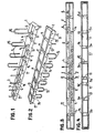
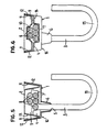
- FIGS. 5 and 6 show two sections of the reinforcement iron holder according to lines V-V, VI-VI of FIG. 3.
- the reinforcing iron holder consists of a box-shaped element 1 and a cover part 2 as well as the reinforcing iron 3.
- the box-shaped element forms the chest side, i.e. the main wall into which the reinforcing iron holder is concreted is facing.
- the cover part for the breast side.
- the hollow body 16 formed from the box-shaped element 1 and the cover part has a trapezoidal cross section, the shorter side being arranged on the breast side.
- other cross sections such as rectangular, semicircular or trapezoidal cross sections in the reverse sense, i.e.
- the top of the box-shaped element has transverse ribs 4 and, at the push-through openings 5, holding parts 6 formed integrally with this element.
- the inward transverse ribs 4 do not have a uniform cross section, but instead form steps 7 which serve to hold the bent connecting legs 8 of the reinforcing bars.
- the gradations 7 forming recesses are arranged at different points with respect to the longitudinal central axis and have different lengths. It can be seen from FIG.
- the reinforcing bars are inserted from both ends of the box-shaped element in such a way that the free ends of the legs of the reinforcing bars point towards the other end of the element, and it is clearly evident that the recesses are such must be trained so that, counted from the end, they can first pick up or hold one, then two, three, four, etc. legs.
- the arrangement according to FIG. 3 also shows that the legs first lie next to one another, then also one above the other, these legs having an angle with respect to the longitudinal central axis of the box-shaped element.
- the cover part also has transverse ribs 9 which are arranged opposite the transverse ribs 4 of the box-shaped element.
- the function of the inwardly directed transverse ribs 9 can be clearly seen from FIGS. 3 and 4, that is to say that the transverse ribs which also protrude on the inside also serve to hold the reinforcing iron legs.
- the ribs 9 form the counterpart to the ribs 4, they are Ribs 9 a, b, c and d, that is, in the places where the reinforcing iron legs come to lie side by side as flat hold-down parts, while the remaining ribs 9 e, f, g, h have recesses 10 to the upper position of the Take up reinforcement iron legs.
- the cover part 2 is arranged inside the box-shaped element, i.e. the longitudinal wall 11 of the cover part runs parallel and inside to the longitudinal wall 12 of the box-shaped element.
- This outer longitudinal wall 11 is adjoined by an inner longitudinal wall 13, so that the longitudinal walls of the cover part form a V-shaped or U-shaped longitudinal wall, which wall is continued through the transverse sides.
- the two longitudinal walls have passages 14 which engage over the transverse ribs 4.
- the fact that the longitudinal walls of the cover part protrude into the box-shaped element results in an additional mounting and securing of the reinforcing iron legs. In addition, this results in a tight seal that prevents the penetration of concrete, which prevents the reinforcing bars from becoming dirty.
- the cover part is spot welded or tacked or glued to the box-shaped element 17.
- the box-shaped element and the cover part are made of plastic, both the transverse ribs and the V-shaped or U-shaped walls of the cover part increasing the stability of the two plastic parts, so that a relatively thin-walled and thus inexpensive element is produced can.
- metal for example expanded metal or wood.
- Both the breast-side transverse ribs 4 and the holding parts 6 also bring about a toothing of the concrete part to be connected.
- the hollow body can easily be shortened from one side, as shown in FIG. 3 or 4 from the right side.
Landscapes
- Engineering & Computer Science (AREA)
- Architecture (AREA)
- Mechanical Engineering (AREA)
- Civil Engineering (AREA)
- Structural Engineering (AREA)
- Joining Of Building Structures In Genera (AREA)
- Reinforcement Elements For Buildings (AREA)
- Forms Removed On Construction Sites Or Auxiliary Members Thereof (AREA)
Claims (9)
Priority Applications (5)
| Application Number | Priority Date | Filing Date | Title |
|---|---|---|---|
| EP84810301A EP0165367B1 (fr) | 1984-06-21 | 1984-06-21 | Support de fers d'armature en attente pour la reprise du coulage dans les ouvrages en béton |
| AT84810301T ATE35437T1 (de) | 1984-06-21 | 1984-06-21 | Armierungseisenhalter zur verwendung bei anschlussbetonierungen. |
| DE8484810301T DE3472430D1 (en) | 1984-06-21 | 1984-06-21 | Reinforcement-iron holder for use in joining cast concrete work |
| CA000483740A CA1259202A (fr) | 1984-06-21 | 1985-06-12 | Fixation de tige d'armature pour le betonnage d'ouvrages a raccords |
| AU43702/85A AU582163B2 (en) | 1984-06-21 | 1985-06-14 | A reinforcing rod holder for use in connection-type concreting operations |
Applications Claiming Priority (1)
| Application Number | Priority Date | Filing Date | Title |
|---|---|---|---|
| EP84810301A EP0165367B1 (fr) | 1984-06-21 | 1984-06-21 | Support de fers d'armature en attente pour la reprise du coulage dans les ouvrages en béton |
Publications (2)
| Publication Number | Publication Date |
|---|---|
| EP0165367A1 EP0165367A1 (fr) | 1985-12-27 |
| EP0165367B1 true EP0165367B1 (fr) | 1988-06-29 |
Family
ID=8193025
Family Applications (1)
| Application Number | Title | Priority Date | Filing Date |
|---|---|---|---|
| EP84810301A Expired EP0165367B1 (fr) | 1984-06-21 | 1984-06-21 | Support de fers d'armature en attente pour la reprise du coulage dans les ouvrages en béton |
Country Status (5)
| Country | Link |
|---|---|
| EP (1) | EP0165367B1 (fr) |
| AT (1) | ATE35437T1 (fr) |
| AU (1) | AU582163B2 (fr) |
| CA (1) | CA1259202A (fr) |
| DE (1) | DE3472430D1 (fr) |
Families Citing this family (3)
| Publication number | Priority date | Publication date | Assignee | Title |
|---|---|---|---|---|
| EP0230206B1 (fr) * | 1986-01-15 | 1990-07-18 | Pebea N.V. | Support de fers d'armature en attente pour la reprise du collage dans les ouvrages en béton |
| AU657707B2 (en) * | 1990-11-02 | 1995-03-23 | Boral Building Services Pty Limited | Continuity strip for reinforced concrete |
| DE202006008530U1 (de) * | 2006-05-26 | 2006-08-17 | Max Frank Gmbh & Co. Kg | Verwahrungselement |
Family Cites Families (6)
| Publication number | Priority date | Publication date | Assignee | Title |
|---|---|---|---|---|
| US4325533A (en) * | 1979-08-23 | 1982-04-20 | Sigma Bauelemente Gmbh | Housing device for isolating connecting reinforcements at joints between first and subsequently poured concrete structures |
| EP0026803B1 (fr) * | 1979-10-03 | 1982-12-29 | Losinger AG | Dispositif de coffrage avec une plaque en faux-oeuvre et des armatures en attente |
| DE3105889A1 (de) * | 1981-02-18 | 1982-11-04 | Döllen, Heinz von, 5840 Schwerte | Vorrichtung zur aufnahme von in betonbauteile teilweise einzugiessende verbindungsstaehle |
| DE3127087C2 (de) * | 1981-07-09 | 1986-04-10 | Sigma Bauelemente Gmbh, 4800 Bielefeld | Vorrichtung zum Verwahren von Bewehrungsstählen |
| DE3201918C1 (de) * | 1982-01-22 | 1983-08-25 | Sigma Bauelemente Gmbh, 4800 Bielefeld | Vorrichtung zum Verwahren von Bewehrungsstaehlen sowie Verfahren zu deren Herstellung und Vorrichtung zur Durchfuehrung des Verfahrens |
| DE3211563C2 (de) * | 1982-02-25 | 1985-03-28 | Bernd 6451 Mainhausen Reichelt | Schalungs- und Verwahrungselement |
-
1984
- 1984-06-21 DE DE8484810301T patent/DE3472430D1/de not_active Expired
- 1984-06-21 AT AT84810301T patent/ATE35437T1/de not_active IP Right Cessation
- 1984-06-21 EP EP84810301A patent/EP0165367B1/fr not_active Expired
-
1985
- 1985-06-12 CA CA000483740A patent/CA1259202A/fr not_active Expired
- 1985-06-14 AU AU43702/85A patent/AU582163B2/en not_active Ceased
Also Published As
| Publication number | Publication date |
|---|---|
| CA1259202A (fr) | 1989-09-12 |
| ATE35437T1 (de) | 1988-07-15 |
| AU4370285A (en) | 1986-01-02 |
| AU582163B2 (en) | 1989-03-16 |
| DE3472430D1 (en) | 1988-08-04 |
| EP0165367A1 (fr) | 1985-12-27 |
Similar Documents
| Publication | Publication Date | Title |
|---|---|---|
| EP0131841B1 (fr) | Ancrage pour un panneau stratifié | |
| DE2808484C2 (fr) | ||
| DE60202004T2 (de) | Anordnung von zwei aneinander zu verbindende Kunststofffahrwerkteilen | |
| CH651730A5 (de) | Koffer. | |
| DE570520C (de) | Tuer, insbesondere fuer geschlossene Wagenkasten bei Kraftfahrzeugen | |
| DE1283740B (de) | Fischkasten aus Kunststoff | |
| DE4007391C2 (de) | Befestigungsflansch für eine Abdeckleiste | |
| EP0165367B1 (fr) | Support de fers d'armature en attente pour la reprise du coulage dans les ouvrages en béton | |
| DE2436244A1 (de) | Versteifungselement fuer kraftfahrzeugseitenwaende | |
| DE3441500C2 (de) | Regalboden aus Schichtwerkstoff, insbesondere Metallblech | |
| DE2952724C2 (de) | Wärmetauscher | |
| DE8619575U1 (de) | Freitragende Bodenplatte | |
| CH656418A5 (de) | Armierungseisenhalter mit armierungseisen zur verwendung bei anschlussbetonierungen. | |
| EP0357817B1 (fr) | Rayonnage en bois à insertion de tablettes à des niveaux variables | |
| DE7711771U1 (de) | Bausatz fuer regale o.dgl. | |
| DE3220847A1 (de) | Vorrichtung zum verwahren von verbindungsstaehlen fuer betonbauteile | |
| DE3535294A1 (de) | Vorrichtung zum einsetzen in eine schalung fuer ein betonteil | |
| DE8417655U1 (de) | Vorrichtung zum verwahren von verbindungsstaehlen fuer betonbauteile | |
| DE3503053C2 (fr) | ||
| DE821035C (de) | Schlosstasche fuer Grubenstempel | |
| EP0397293B1 (fr) | Rail de fixation pour tôles à ondes trapézoidales pour la technique de la construction | |
| DE2418313C2 (de) | Rahmenkonstruktion, die einen Lastboden beispielsweise eines Lastfahrzeuges umgibt | |
| DE3442182C2 (de) | Vorrichtung zum Verwahren von Verbindungsstählen für Betonbauteile | |
| DE3603434C2 (fr) | ||
| DE19511822C2 (de) | Bewehrungsanschluß |
Legal Events
| Date | Code | Title | Description |
|---|---|---|---|
| PUAI | Public reference made under article 153(3) epc to a published international application that has entered the european phase |
Free format text: ORIGINAL CODE: 0009012 |
|
| AK | Designated contracting states |
Designated state(s): AT BE CH DE FR GB IT LI LU NL SE |
|
| 17P | Request for examination filed |
Effective date: 19860619 |
|
| 17Q | First examination report despatched |
Effective date: 19870326 |
|
| ITF | It: translation for a ep patent filed |
Owner name: BARZANO' E ZANARDO MILANO S.P.A. |
|
| RAP1 | Party data changed (applicant data changed or rights of an application transferred) |
Owner name: PAWE AG Owner name: PEBEA N.V. |
|
| RBV | Designated contracting states (corrected) |
Designated state(s): AT BE CH DE FR GB IT LI LU NL SE |
|
| GRAA | (expected) grant |
Free format text: ORIGINAL CODE: 0009210 |
|
| RAP1 | Party data changed (applicant data changed or rights of an application transferred) |
Owner name: PAWE AG Owner name: PEBEA N.V. |
|
| AK | Designated contracting states |
Kind code of ref document: B1 Designated state(s): AT BE CH DE FR GB IT LI LU NL SE |
|
| REF | Corresponds to: |
Ref document number: 35437 Country of ref document: AT Date of ref document: 19880715 Kind code of ref document: T |
|
| GBT | Gb: translation of ep patent filed (gb section 77(6)(a)/1977) | ||
| REF | Corresponds to: |
Ref document number: 3472430 Country of ref document: DE Date of ref document: 19880804 |
|
| ET | Fr: translation filed | ||
| PLBI | Opposition filed |
Free format text: ORIGINAL CODE: 0009260 |
|
| PGFP | Annual fee paid to national office [announced via postgrant information from national office to epo] |
Ref country code: FR Payment date: 19890518 Year of fee payment: 6 |
|
| 26 | Opposition filed |
Opponent name: FRANKHAUSER, PETER / WITSCHI, HEINZ Effective date: 19890328 |
|
| PG25 | Lapsed in a contracting state [announced via postgrant information from national office to epo] |
Ref country code: SE Effective date: 19890622 |
|
| PG25 | Lapsed in a contracting state [announced via postgrant information from national office to epo] |
Ref country code: LU Free format text: LAPSE BECAUSE OF NON-PAYMENT OF DUE FEES Effective date: 19890630 Ref country code: BE Effective date: 19890630 |
|
| PGFP | Annual fee paid to national office [announced via postgrant information from national office to epo] |
Ref country code: GB Payment date: 19890630 Year of fee payment: 6 |
|
| NLR1 | Nl: opposition has been filed with the epo |
Opponent name: FRANKHAUSER, PETER / WITSCHI, HEINZ |
|
| BERE | Be: lapsed |
Owner name: PEBEA N.V. Effective date: 19890630 |
|
| PG25 | Lapsed in a contracting state [announced via postgrant information from national office to epo] |
Ref country code: NL Effective date: 19900101 |
|
| NLV4 | Nl: lapsed or anulled due to non-payment of the annual fee | ||
| PG25 | Lapsed in a contracting state [announced via postgrant information from national office to epo] |
Ref country code: DE Effective date: 19900301 |
|
| PG25 | Lapsed in a contracting state [announced via postgrant information from national office to epo] |
Ref country code: GB Effective date: 19900621 |
|
| GBPC | Gb: european patent ceased through non-payment of renewal fee | ||
| PG25 | Lapsed in a contracting state [announced via postgrant information from national office to epo] |
Ref country code: FR Effective date: 19910228 |
|
| REG | Reference to a national code |
Ref country code: FR Ref legal event code: ST |
|
| PLBM | Termination of opposition procedure: date of legal effect published |
Free format text: ORIGINAL CODE: 0009276 |
|
| STAA | Information on the status of an ep patent application or granted ep patent |
Free format text: STATUS: OPPOSITION PROCEDURE CLOSED |
|
| 27C | Opposition proceedings terminated |
Effective date: 19910209 |
|
| EUG | Se: european patent has lapsed |
Ref document number: 84810301.6 Effective date: 19900418 |
|
| PGFP | Annual fee paid to national office [announced via postgrant information from national office to epo] |
Ref country code: AT Payment date: 19950629 Year of fee payment: 12 |
|
| PG25 | Lapsed in a contracting state [announced via postgrant information from national office to epo] |
Ref country code: AT Effective date: 19960621 |
|
| PGFP | Annual fee paid to national office [announced via postgrant information from national office to epo] |
Ref country code: CH Payment date: 19980630 Year of fee payment: 15 |
|
| PG25 | Lapsed in a contracting state [announced via postgrant information from national office to epo] |
Ref country code: LI Free format text: LAPSE BECAUSE OF NON-PAYMENT OF DUE FEES Effective date: 19990630 Ref country code: CH Free format text: LAPSE BECAUSE OF NON-PAYMENT OF DUE FEES Effective date: 19990630 |
|
| REG | Reference to a national code |
Ref country code: CH Ref legal event code: PL |