EP0165228B1 - Vorrichtung zum Belüften von strömenden Medien - Google Patents
Vorrichtung zum Belüften von strömenden Medien Download PDFInfo
- Publication number
- EP0165228B1 EP0165228B1 EP19850890019 EP85890019A EP0165228B1 EP 0165228 B1 EP0165228 B1 EP 0165228B1 EP 19850890019 EP19850890019 EP 19850890019 EP 85890019 A EP85890019 A EP 85890019A EP 0165228 B1 EP0165228 B1 EP 0165228B1
- Authority
- EP
- European Patent Office
- Prior art keywords
- frustoconical
- rings
- air
- insert
- conical
- Prior art date
- Legal status (The legal status is an assumption and is not a legal conclusion. Google has not performed a legal analysis and makes no representation as to the accuracy of the status listed.)
- Expired - Lifetime
Links
- 238000005273 aeration Methods 0.000 title description 6
- XLYOFNOQVPJJNP-UHFFFAOYSA-N water Substances O XLYOFNOQVPJJNP-UHFFFAOYSA-N 0.000 claims description 21
- 238000009423 ventilation Methods 0.000 description 24
- 239000003570 air Substances 0.000 description 14
- QVGXLLKOCUKJST-UHFFFAOYSA-N atomic oxygen Chemical compound [O] QVGXLLKOCUKJST-UHFFFAOYSA-N 0.000 description 5
- 239000001301 oxygen Substances 0.000 description 5
- 229910052760 oxygen Inorganic materials 0.000 description 5
- 239000012080 ambient air Substances 0.000 description 4
- 239000007789 gas Substances 0.000 description 2
- 239000010865 sewage Substances 0.000 description 2
- 230000000694 effects Effects 0.000 description 1
- 210000003608 fece Anatomy 0.000 description 1
- 238000007654 immersion Methods 0.000 description 1
- 239000010871 livestock manure Substances 0.000 description 1
- 238000004519 manufacturing process Methods 0.000 description 1
- 239000000203 mixture Substances 0.000 description 1
- 230000008929 regeneration Effects 0.000 description 1
- 238000011069 regeneration method Methods 0.000 description 1
- 239000010801 sewage sludge Substances 0.000 description 1
- 239000010802 sludge Substances 0.000 description 1
- 238000011144 upstream manufacturing Methods 0.000 description 1
Images

Classifications
-
- B—PERFORMING OPERATIONS; TRANSPORTING
- B01—PHYSICAL OR CHEMICAL PROCESSES OR APPARATUS IN GENERAL
- B01F—MIXING, e.g. DISSOLVING, EMULSIFYING OR DISPERSING
- B01F23/00—Mixing according to the phases to be mixed, e.g. dispersing or emulsifying
- B01F23/20—Mixing gases with liquids
- B01F23/23—Mixing gases with liquids by introducing gases into liquid media, e.g. for producing aerated liquids
- B01F23/232—Mixing gases with liquids by introducing gases into liquid media, e.g. for producing aerated liquids using flow-mixing means for introducing the gases, e.g. baffles
- B01F23/2326—Mixing gases with liquids by introducing gases into liquid media, e.g. for producing aerated liquids using flow-mixing means for introducing the gases, e.g. baffles adding the flowing main component by suction means, e.g. using an ejector
-
- C—CHEMISTRY; METALLURGY
- C02—TREATMENT OF WATER, WASTE WATER, SEWAGE, OR SLUDGE
- C02F—TREATMENT OF WATER, WASTE WATER, SEWAGE, OR SLUDGE
- C02F3/00—Biological treatment of water, waste water, or sewage
- C02F3/02—Aerobic processes
- C02F3/12—Activated sludge processes
- C02F3/1278—Provisions for mixing or aeration of the mixed liquor
- C02F3/1294—"Venturi" aeration means
-
- B—PERFORMING OPERATIONS; TRANSPORTING
- B01—PHYSICAL OR CHEMICAL PROCESSES OR APPARATUS IN GENERAL
- B01F—MIXING, e.g. DISSOLVING, EMULSIFYING OR DISPERSING
- B01F23/00—Mixing according to the phases to be mixed, e.g. dispersing or emulsifying
- B01F23/20—Mixing gases with liquids
- B01F23/23—Mixing gases with liquids by introducing gases into liquid media, e.g. for producing aerated liquids
- B01F23/232—Mixing gases with liquids by introducing gases into liquid media, e.g. for producing aerated liquids using flow-mixing means for introducing the gases, e.g. baffles
-
- C—CHEMISTRY; METALLURGY
- C02—TREATMENT OF WATER, WASTE WATER, SEWAGE, OR SLUDGE
- C02F—TREATMENT OF WATER, WASTE WATER, SEWAGE, OR SLUDGE
- C02F7/00—Aeration of stretches of water
-
- Y—GENERAL TAGGING OF NEW TECHNOLOGICAL DEVELOPMENTS; GENERAL TAGGING OF CROSS-SECTIONAL TECHNOLOGIES SPANNING OVER SEVERAL SECTIONS OF THE IPC; TECHNICAL SUBJECTS COVERED BY FORMER USPC CROSS-REFERENCE ART COLLECTIONS [XRACs] AND DIGESTS
- Y02—TECHNOLOGIES OR APPLICATIONS FOR MITIGATION OR ADAPTATION AGAINST CLIMATE CHANGE
- Y02W—CLIMATE CHANGE MITIGATION TECHNOLOGIES RELATED TO WASTEWATER TREATMENT OR WASTE MANAGEMENT
- Y02W10/00—Technologies for wastewater treatment
- Y02W10/10—Biological treatment of water, waste water, or sewage
Definitions
- the invention relates to a device for aerating flowing media, in particular water, with an inflow pipe, a nozzle, a ventilation piece and an adjoining downpipe.
- a known device of the applicant which is described in AT-PS 37t 373 comprises a suction part, a ventilation piece and a downpipe.
- the suction part is based on the shape of the freely flowing water jet.
- the beam narrows after a deflection of 75 or 80 ° and is guided through a diffuser with a slight increase in cross-section.
- a side wall is built up from scale-like overlapping, strip-shaped lamellae. There is a free space between the fins and a connection with the ambient air or the oxygen to be introduced or another gas.
- the water flowing in the interior of the ventilation chamber via the ventilation lamellae sucks in air, which is caused by the water flow in the subsequent downpipe to the floor.
- B. a container with water to be aerated.
- a device for aerating flowing media in particular water, with an inflow pipe, a nozzle, an aeration piece with internally concentric superposed and spaced-apart truncated-cone-shaped pipe pieces and an adjoining downpipe is known.
- the invention aims to further improve the optimizability and the efficiency of this known device for aerating flowing media.
- the interior of the ventilation piece is provided concentrically one above the other and at a distance from one another thin-walled frusto-conical pipe pieces which are mounted in the area of their base circle on the inside of the housing wall of the ventilation piece, in particular on rings or clamped between rings which form the cylindrical housing wall of the Form ventilation piece and each have openings as suction slots for air intake.
- rotationally symmetrical bodies namely the frustoconical tube pieces, are provided, which are mounted overlapping one another in such a way that they are, so to speak, inserted into one another.
- the water flowing through the suction piece through the ventilation piece and the nozzle through the ventilation piece takes more air than known devices due to the special design of the ventilation piece.
- a special embodiment is characterized in that the frusto-conical tube pieces enclose a hollow, conical, coaxial insert, the interior of which is connected to the atmosphere for sucking in air and the lateral surface of which has suction slots.
- the efficiency of the device is increased still further, because it allows the central core area of the water column to be aerated directly.
- the conical insert has a step-shaped lateral surface with suction slots and if cylindrical guide plates are optionally provided on the steps which protrude above the steps. In this case, the conical insert automatically adjusts to the water level. The immersion depth always corresponds to the height of the tapered insert.
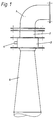
- FIG. 1 shows a device according to the invention in view
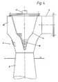
- FIG. 2 shows the nozzle and the ventilation piece in cross section
- FIG. 3 shows a variation of a detail from FIG. 2
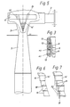
- FIG. 4 shows another embodiment of a ventilation piece with a conical insert
- FIGS. 6 and 7 variants of a detail from FIG. 4 or 5.
- a device for aerating flowing media consists of an inflow pipe 1 which is supplied with water or the like by means of a pump or on the basis of an existing gradient, the shape of which is largely modeled on a freely flowing water jet, so that the hydrodynamic losses can be kept low.
- a nozzle 2 (Venturi nozzle, diffuser nozzle) is flanged onto it.
- a ventilation piece 3 which consists of two concentric chambers.
- An air supply 4 opens into the outer chamber.
- a downpipe 5 is connected to the ventilation piece 3, the cross section of which slowly increases.
- Fig. 2 shows the nozzle 2 and the ventilation piece 3 in cross section in the nozzle designed as a nozzle 2, the inflow pipe 1 opens.
- the nozzle 2 has a cross-sectional constriction 6 and an adjoining, conically widening part 7, which already opens into the interior of the ventilation piece 3.
- the latter consists of a housing wall 8 on the Sawtooth-like conical surfaces provided on the inside, each of which carries thin-walled, conical tubular pieces 9 arranged concentrically one above the other and at a distance from one another. Bores 10 of the housing wall 8 open below each conical tubular piece 9.
- the housing wall 8 is surrounded by a jacket 12 so that a chamber 11 is formed into which air or gas is supplied via the nozzle 4. The air is distributed in the annular chamber 11 and passes through the bores arranged in rows into the interior of the ventilation piece 3 as soon as water flows there and the suction effect of the water tearing the conical tube pieces 9 out of the water.
- the chamber 11 can also be dispensed with.
- the jacket 12 is then omitted so that the ambient air can be sucked in directly through the bores 10.
- the downpipe 5 connects to the ventilation piece 3.
- the opening angle of the downpipe 5 is to be matched to the amount of air drawn in (5, 5 ').
- the housing wall consists of a plurality of individual rings 13 arranged one above the other, which are held together in a packet-like manner by external tensioning screws.
- Each ring 13 has an inclined inner surface, on each of which a conical tubular piece 9 is seated.
- Each frustoconical tube piece 9 is on the one hand on the inclined surface of a ring 13 laterally and is displaced due to its projection from the end face of the ring 13 arranged above when tightening the rings 13 in the axial direction so that a press fit between the frustoconical tube piece 9 and the Ring 13 results.
- the frustoconical tube pieces 9 are clamped between two adjacent rings 13 when the rings 1.3 are clamped together. Bores 10 are provided in the rings 13. This embodiment results in a particularly simple manufacture and also the possibility of increasing the amount of air to be introduced or reducing it upon removal by adding rings 13 with pipe pieces 9.
- FIG. 4 shows a ventilation piece 3 ', the outer wall of which is constructed as shown in FIG. 2 or 3, but which has a hollow conical coaxial insert 14 on the inside.
- the insert is attached to the top wall of a chamber 15, which is connected upstream of the ventilation piece 3 'and into which the nozzle 2 opens.
- the frusto-conical insert 14 has a lateral surface 16 formed from rings or steps which adjoin one another in the manner of a telescope. It can be formed in one piece.
- the interior of the insert 14 is hollow and connected to an air supply or to the ambient air via a line or opening 17. This air exits through bores 18 and 18 'in the flat annular surfaces 16 at the end (FIG. 6) or is torn out when water flows around the cone insert 14.
- cylindrical, thin-walled tube pieces 22 as water baffles on the cylindrical, annular outer surface 16, which cover the bores 18, 18 ', as shown in FIG. 7.
- the conical insert 14 the surface of which is designed in the sense of FIG. 6 or 7 already described, is arranged on a float 19.
- the float 19 has openings so that the ambient air can enter the interior and be released as a result of the flow through the bores according to Fig. 6 or 7.
- bores 20 can also be provided in the float, which guide air to the outer surface of the conical insert 14 '. These holes 20 can be closed by a stubble 21.
- the device according to the invention can be used in sewage treatment plants with aeration tanks and settling tanks in the aeration tanks.
- the downpipe dips into the aeration tank and extends to the bottom of the same.
- a suction line and a pump By means of a suction line and a pump, the sewage sludge from the activated sludge tank is returned to the device according to the invention, so that a regeneration cycle is formed.
- the device according to the invention can also be used for deep aeration of lakes or ponds.
Landscapes
- Chemical & Material Sciences (AREA)
- Chemical Kinetics & Catalysis (AREA)
- Life Sciences & Earth Sciences (AREA)
- Hydrology & Water Resources (AREA)
- Engineering & Computer Science (AREA)
- Environmental & Geological Engineering (AREA)
- Water Supply & Treatment (AREA)
- Organic Chemistry (AREA)
- Biodiversity & Conservation Biology (AREA)
- Microbiology (AREA)
- Aeration Devices For Treatment Of Activated Polluted Sludge (AREA)
Description
- Die Erfindung betrifft eine Vorrichtung zum Belüften von strömenden Medien, insbesondere Wasser, mit einem Zuflußrohr, einer Düse, einem Belüftungsstück und einem daran anschließenden Fallrohr. Zur Regenerierung des Wassers von Seen oder Teichen wie auch zur Belüftung von Gülle im landwirtschaftlichen Bereich im Zusammenhang mit Kläranlagen ist es erforderlich, Sauerstoff bzw. ein Gas-Luftgemisch in die genannten strömenden Medien einzutragen, denn ein großer Teil der im Wasser lebenden Organismen ist auf einen ausreichenden Sauerstoffgehalt des Wassers angewiesen. Jede aerobe Lebensgemeinschift benötigt bestimmte Mindestkonzentritionen an gelöstem Sauerstoff. Reichen die Größen der Grenzflächen Wasser zur Luft und die Turbulenzen an der Wasseroberfläche nicht aus, den erforderlichen Sauerstoffkonzentrationswert herzustellen, dann wird künstliche Belüftung mittels Vorrichtungen der eingangs beschriebenen Art eingesetzt.
- Ein bekanntes Gerät des Anmelders, das in der AT-PS 37t 373 beschrieben ist umfaßt einen Ansaugsteil, ein Belüftungsstück und ein Fallrohr. Der Ansaugteil ist der Form des frei ausströmenden Wasserstrahles nachempfunden. Der Strahlverengt sich nach einer Umlenkung von 75 bzw. 80° und wird durch einen Diffusor mit geringfügiger Querschnittserweiterung geführt. In dem anschließenden Belüftungsstück mit rechteckigem Querschnitt ist eine Seitenwand aus schuppenartig überlappenden, leistenförmigen Lamellen aufgebaut. Es besteht ein freier Zwischenraum zwischen den Lamellen sowie eine Verbindung mit der Umgebungsluft bzw. dem einzutragenden Sauerstoff oder einem anderen Gas. Das im Inneren der Belüftungskammer über die Belüftungslamellen strömende Wasser saugt Luft an, die durch den Wasserstrom in dem anschließenden Fallrohr an den Boden z. B. eines Behälters mit zu belüftendem Wasser geführt wird.
- Aus der AT-B 337 626 ist eine Vorrichtung zum Belüften von strömenden Medien, insbesondere Wasser, mit einem Zuflußrohr, einer Düse, einem Belüftungsstück mit im Inneren konzentrisch übereinander und im Abstand zueinander angeordneten dünnwandigen kegelstumpfförmigen Rohrstücken und einem daran anschließenden Fallrohr bekannt. Die Erfindung zielt darauf ab, die Optimierbarkeit und den Wirkungsgrad dieser bekannten vorrichtung zum Belüften von strömenden Medien weiter zu verbessern. Dies wird erfindungsgemäß dadurch erreicht, daß im Inneren des Belüftungsstückes konzentrisch übereinander und im Abstand zueinander dünnwandige kegelstumpfförmige Rohrstücke vorgesehen sind, die im Bereich ihres Basiskreises auf der Innenseite der Gehäusewand des Belüftungsstückes insbesondere auf Ringen montiert oder zwischen Ringen eingespannt sind, die die zylindrische Gehäusewand des Belüftungsstückes bilden und die jeweils Öffnungen als Ansaugschlitze zum Lufteintritt aufweisen. An Stelle der einleitend genannten leistenförmigen Lamellen sind rotationssymmetrische Körper, nämlich die kegelstumpfförmigen Rohrstücke vorgesehen, die einander überlappend so montiert sind, daß sie gewissermaßen ineinander stecken. Das über das ansaugende Zuflußrohr und die Düse durch das Belüftungsstück fließende Wasser nimmt infolge der speziellen Ausbildung des Belüftungsstückes mehr Luft mit, als bekannte Geräte.
- Eine besondere Ausführungsform ist dadurch gekennzeichnet, daß die kegelstumpfförmigen Rohrstücke einen hohlen kegelförmigen, koaxialen Einsatz umschließen, dessen Inneres zum Ansaugen von Luft mit der Atmosphäre in Verbindung steht und dessen Mantelfläche Ansaugschlitze aufweist. Dadurch wird der Wirkungsgrad der Vorrichtung noch weiter erhöht, denn es kann auf diese Weise auch der zentrale Kembereich der Wassersäule unmittelbar belüftet werden. Es ist zweckmäßig, wenn der kegelförmige Einsatz eine stufenförmige Mantelfläche mit Ansaugschlitzen aufweist und wenn gegebenenfalls zylindrische Leitbleche auf den Stufen vorgesehen sind, die die Stufen überragen. In diesem Fall stellt sich der kegelige Einsatz auf den Wasserspiegel stelbsttätig ein. Die Eintauchtiefe entspricht dadurch immer der Höhe des kegeligen Einsatzes.
- Ausführungsbeispiele des Erfindungsgegenstandes sind in den Zeichnungen dargestellt
- Fig. 1 zeigt eine Vorrichtung gemäß der Erfindung in Ansicht, Fig.2 die Düse und das Belüftungsstück im Querschnitt, Fig.3 eine Variation eines Details aus Fig. 2, Fig. 4 eine andere Ausführung eines Belüftungsstückes mit kegelförmigem Einsatz, Fig. 5 eine Variante zu Fig. 4 mit Schwimmereinsatz und die Fig. 6 und 7 Varianten eines Details von Fig. 4 oder 5.
- Gemäß Fig. 1 besteht eine Vorrichtung zum Belüften von strömenden Medien entsprechend der Erfindung aus einem mittels einer Pumpe oder auf Grund eines vorhandenen Gefälles mit Wasser od. dgl. beschickten Zuflußrohr 1, dessen Form einen frei ausströmenden Wasserstrahl weitgehend nachgebildet ist, damit die hydrodynamischen Verluste gering gehalten werden können. Daran angeflanscht ist eine Düse 2 (Venturidüse, Diffusordüse). Es folgt ein Belüftungsstück 3, das aus zwei konzentrischen Kammern besteht In die äußere Kammer mündet eine Luftzuführung 4 ein. Schließlich ist an das Belüftungsstück 3 ein Fallrohr 5 angeschlossen, dessen Querschnitt langsam zunimmt.
- Fig. 2 zeigt die Düse 2 und das Belüftungsstück 3 im Querschnitt In den als Düse 2 ausgebildeten Stutzen mündet das Zuflußrohr 1 ein. Die Düse 2 weist eine Querschnittsverengung 6 sowie einen daran anschließenden, sich konisch verbreiternden Teil 7 auf, der bereits in dis Innere des Belüftungsstückes 3 einmündet. Letzteres besteht nach Fig. 2 aus einer Gehäusewand 8 mit an der Innenseite vorgesehenen sägezahnartigen Konusflächen, die jeweils konzentrisch übereinander und im Abstand zueinander angeordnete dünnwandige kegelförmige Rohrstücke 9 tragen. Unterhalb jedes kegelförmigen Rohrstückes 9 münden Bohrungen 10 der Gehäusewand 8 ein. Die Gehäusewand 8 ist von einem Mantel 12 umgeben, so daß sich eine Kammer 11 bildet in die Luft oder Gas über den Stutzen 4 zugeführt wird. Die Luft verteilt sich in der ringförmigen Kammer 11 und gelangt durch die in Reihen angeordneten Bohrungen in das Innere des Belüftungsstückes 3, sobald dort Wasser fließt und die Sogwirkung des Ober die kegelförmigen Rohrstücke 9 strömenden Wassers Luft herausreißt.
- In manchen Fällen kann auch auf die Kammer 11 verzichtet werden. Es entfällt dann der Mantel 12, so daß die Umgebungsluft unmittelbar durch die Bohrungen 10 eingesaugt werden kann.
- An das Belüftungsstück 3 schließt das Fallrohr 5 an. Der Öffnungswinkel des Fallrohres 5 ist auf die Menge der angesaugten Luft abzustimmen (5, 5').
- Fig. 3 zeigt eine Ausführungsvariante der Befestigung der kegelförmigen Rohrstücke 9. In diesem Fall besteht die Gehäusewand aus einer Mehrzahl von einzelnen übereinander angeordneten Ringen 13, die durch außen liegende Spannschrauben paketförmig zusammengehalten werden. Jeder Ring 13 hat eine schräge Innenfläche, auf der jeweils ein kegelförmiges Rohrstück 9 sitzt. Jedes kegelstumpfförmige Rohrstück 9 liegt einerseits an der Schrägfläche des einen Ringes 13 seitlich an und wird infolge seines Überstandes von der Stirnfläche des darüber angeordneten Ringes 13 beim Zusammenspannen der Ringe 13 so in axialer Richtung verschoben, daß sich ein Preßsitz zwischen dem kegelstumpfförmigen Rohrstück 9 und dem Ring 13 ergibt. Die kegelstumpfförmigen Rohrstücke 9 werden beim Zusammenspannen der Ringe 1.3 jeweils zwischen zwei benachbarten Ringen 13 eingeklemmt In den Ringen 13 sind Bohrungen 10 vorgesehen. Es ergibt sich bei dieser Ausführungsform eine besonders einfache Herstellbarkeit sowie auch die Möglichkeit, durch Ergänzen von Ringen 13 mit Rohrstücken 9 die einzutragende Luftmenge zu vergrößern bzw. bei Entfernen zu verkleinern.
- Nicht dargestellt ist eine Ausführungsform, bei der die Ringe mit den kegelstumpfförmigen Rohrstücken einstückig ausgebildet sind. Die mit scharfen Abreißkanten versehenen Schrägflächen der Ringe übernehmen in diesem Fall die Aufgabe der kegelstumpfförmigen Rohrstücke.
- Fig.4 zeigt ein Belüftungsstück 3', dessen Außenwand so aufgebaut ist, wie dies in Fig. 2 oder 3 dargestellt ist, das jedoch im Inneren einen hohlen kegelförmigen koaxialen Einsatz 14 aufweist. Der Einsatz ist an der Deckwand einer Kammer 15 befestigt, die dem Belüftungsstück 3' vorgeschaltet ist und in welche die Düse 2 einmündet.
- Der kegelstumpfförmige Einsatz 14 hat eine aus teleskopähnlich aneinanderschließenden Ringen oder Stufen gebildete Mantelfläche 16. Er kann einstückig ausgebildet sein. Das Innere des Einsatzes 14 ist hohl und über eine Leitung bzw. Öffnung 17 mit einer Luftzuführung bzw. mit der Umgebungsluft verbunden. Diese Luft tritt durch Bohrungen 18 bzw. 18', in den ebenen Ringflächen 16 stimseitig aus (Fig. 6) bzw. wird herausgerissen, wenn Wasser den Kegeleinsatz 14 umströmt.
- Es können auch zylindrische dünnwandige Rohrstücke 22 als Wasserleitbleche auf die zylindrische ringförmige Mantelfläche 16 aufgesetzt werden, die die Bohrungen 18, 18' abdecken, wie dies in Fig. 7 dargestellt ist.
- Bei Fig. 5 ist der kegelförmige Einsatz 14, dessen Oberfläche im Sinne der bereits beschriebenen Fig. 6 oder 7 ausgebildet, auf einem Schwimmer 19 angeordnet. Der Schwimmer 19 besitzt Öffnungen, damit die Umgebungsluft in das Innere eintreten und infolgeder Strömung durch die Bohrungen gemäß Fig. 6 oder 7 abgegeben werden kann. Ferner können im Schwimmer noch Bohrungen 20 vorgesehen sein, die Luft an die Außenfläche des kegelförmigen Einsatzes 14' führen. Diese Bohrungen 20 können durch einen Stoppel 21 verschlossen werden.
- In den Fig. 4 und 5 ist lediglich der kegelförmige Einsatz 14, 14' in seinen Einzelheiten dargestellt. Die jeweiligen Außenwände der Belüftungsstücke 3 sind gemäß Fig. 2 bzw. 3 aufgebaut. Aus Gründen der Übersichtlichkeit wurde dies in Fig. 4 und 5 nicht nochmals dargestellt. Die Vorrichtung ist mit verschlechertem Wirkungsgrad selbstverständlich auch nur mit dem kegelförmigen Einsatz 14, 14' im Belüftungsstück 3 betriebsfähig.
- Die erfindungsgemäße Vorrichtung kann etwa bei Kläranlagen mit Belebungsbecken und Absetzbecken in dem Belebungsbecken eingesetzt werden. Das Fallrohr taucht in das Belebungsbecken ein und reicht bis etwa zum Grund desselben. Mittels einer Saugleitung und einer Pumpe wird der erfindungsgemäßen Vorrichtung der Klärschlamm aus dem Belebungsbecken wieder zugeführt, so daß sich ein Regenerationskreislauf bildet.
- Die erfindungsgemäße Vorrichtung kann auch zur Tiefenbelüftung von Seen oder Teichen herangezogen werden.
Claims (4)
Applications Claiming Priority (2)
| Application Number | Priority Date | Filing Date | Title |
|---|---|---|---|
| AT28584A AT383338B (de) | 1984-01-30 | 1984-01-30 | Vorrichtung zum belueften von stroemenden medien |
| AT285/84 | 1984-01-30 |
Publications (3)
| Publication Number | Publication Date |
|---|---|
| EP0165228A2 EP0165228A2 (de) | 1985-12-18 |
| EP0165228A3 EP0165228A3 (en) | 1986-11-26 |
| EP0165228B1 true EP0165228B1 (de) | 1990-01-03 |
Family
ID=3486480
Family Applications (1)
| Application Number | Title | Priority Date | Filing Date |
|---|---|---|---|
| EP19850890019 Expired - Lifetime EP0165228B1 (de) | 1984-01-30 | 1985-01-25 | Vorrichtung zum Belüften von strömenden Medien |
Country Status (3)
| Country | Link |
|---|---|
| EP (1) | EP0165228B1 (de) |
| AT (1) | AT383338B (de) |
| DE (1) | DE3575122D1 (de) |
Families Citing this family (6)
| Publication number | Priority date | Publication date | Assignee | Title |
|---|---|---|---|---|
| ZA919256B (en) * | 1990-11-23 | 1992-11-25 | Atomaer Pty Ltd | Gas particle formation |
| DE9302862U1 (de) * | 1993-02-26 | 1993-05-27 | Anton Steinecker Entwicklungs GmbH & Co, 8050 Freising | Belüftungsdüse zum Belüften von organische Substanzen enthaltenden Flüssigkeiten |
| NO20042102A (no) * | 2004-05-21 | 2005-05-30 | Aga As | Dyse ved oksygenering |
| IT202000016327A1 (it) * | 2020-07-06 | 2022-01-06 | Omitaly Srl | Dispositivo generatore di micro e nano bolle |
| CN115253689B (zh) * | 2021-04-29 | 2024-01-26 | 天津膜天膜科技股份有限公司 | 中空纤维纳滤膜气水洗流道及制备方法和使用工艺 |
| CN113307416B (zh) * | 2021-06-29 | 2023-04-07 | 洛阳永宁有色科技有限公司 | 一种多功能污水处理池 |
Family Cites Families (5)
| Publication number | Priority date | Publication date | Assignee | Title |
|---|---|---|---|---|
| AT288294B (de) * | 1968-11-20 | 1971-02-25 | Vogelbusch Gmbh | Vorrichtung zur Begasung von Flüssigkeiten |
| NL7116127A (en) * | 1971-11-24 | 1973-05-28 | Air injector - for aerating eg surface water | |
| AT337626B (de) * | 1974-07-16 | 1977-07-11 | Hutter Karl | Vorrichtung zum inberuhrungbringen von fliessfahigen medien durch injektorwirkung |
| CH604860A5 (de) * | 1976-08-19 | 1978-09-15 | Kaelin J R | |
| AT371373B (de) * | 1981-06-09 | 1983-06-27 | Huetter Karl | Vorrichtung zum belueften von stroemenden medien |
-
1984
- 1984-01-30 AT AT28584A patent/AT383338B/de not_active IP Right Cessation
-
1985
- 1985-01-25 EP EP19850890019 patent/EP0165228B1/de not_active Expired - Lifetime
- 1985-01-25 DE DE8585890019T patent/DE3575122D1/de not_active Expired - Lifetime
Also Published As
| Publication number | Publication date |
|---|---|
| AT383338B (de) | 1987-06-25 |
| DE3575122D1 (de) | 1990-02-08 |
| EP0165228A2 (de) | 1985-12-18 |
| ATA28584A (de) | 1986-11-15 |
| EP0165228A3 (en) | 1986-11-26 |
Similar Documents
| Publication | Publication Date | Title |
|---|---|---|
| DE3887711T2 (de) | Vorrichtung und Verfahren zur Behandlung von unter hohem Druck mit Sauerstoff gesättigtem Wasser. | |
| DE3501175C2 (de) | ||
| DE2556522C3 (de) | Vorrichtung zum Behandeln von stark schäumenden Flüssigkeiten | |
| DE2216304C3 (de) | Einrichtung zur Umwälzung und Belüftung einer sich in einem Belebungsbecken einer Kläranlage befindenden Flüssigkeit | |
| EP0222799B2 (de) | Verfahren zur einbringung von sauerstoff in wasser und vorrichtung zur durchführung des verfahrens | |
| DE3006935C2 (de) | Vorrichtung zum Einleiten von Luft in Abwasser | |
| CH619199A5 (de) | ||
| DE2507698A1 (de) | Verfahren und vorrichtung zur begasung von fluessigkeiten | |
| DE2360569A1 (de) | Verfahren und vorrichtungen zur reinigung und belueftung von aquarien | |
| DE2400653C2 (de) | Verfahren zur Anreicherung einer wäßrigen Flüssigkeit mit Sauerstoff | |
| DE2036424A1 (de) | Aufschaumer fur eine Blutaufbe reitung sanordnung | |
| DE2216917C3 (de) | Vorrichtung zum Lösen von Sauerstoff in Wasser | |
| DE2300157B2 (de) | Verfahren und einrichtung zur biologischen reinigung von abwasser | |
| DE69001250T2 (de) | Vorrichtung für die neutralisation von organischen stoffen und für die beseitigung von phosphor enthaltenden verbindungen in wasserbecken. | |
| EP0165228B1 (de) | Vorrichtung zum Belüften von strömenden Medien | |
| DE69933508T2 (de) | Wirbelgenerator für feine bläschen und verfahren | |
| DE2621517A1 (de) | Wasseraufbereitungsanlage | |
| EP0006597A1 (de) | Verfahren und Vorrichtung zur Belüftung von Wasser | |
| DE3833023C2 (de) | ||
| DE4235558C1 (de) | Verfahren und Vorrichtung zum Lösen eines Gases in einer Flüssigkeit | |
| DE2728585C3 (de) | Vorrichtung zur anaeroben Reinigung von Abwasser | |
| DE4002694C2 (de) | ||
| DE3210473C2 (de) | Tauchbelüfter | |
| DE68902622T2 (de) | Verfahren und vorrichtung fuer die qualitaetsmodifizierung einer grossen wassermenge. | |
| DE2410574A1 (de) | Druckstrahler zum begasen von fluessigkeiten, insbesondere von fermentationsfluessigkeiten und abwasser |
Legal Events
| Date | Code | Title | Description |
|---|---|---|---|
| PUAI | Public reference made under article 153(3) epc to a published international application that has entered the european phase |
Free format text: ORIGINAL CODE: 0009012 |
|
| AK | Designated contracting states |
Designated state(s): CH DE FR GB IT LI |
|
| 17P | Request for examination filed |
Effective date: 19860606 |
|
| PUAL | Search report despatched |
Free format text: ORIGINAL CODE: 0009013 |
|
| AK | Designated contracting states |
Kind code of ref document: A3 Designated state(s): CH DE FR GB IT LI |
|
| 17Q | First examination report despatched |
Effective date: 19880905 |
|
| GRAA | (expected) grant |
Free format text: ORIGINAL CODE: 0009210 |
|
| AK | Designated contracting states |
Kind code of ref document: B1 Designated state(s): CH DE FR GB IT LI |
|
| PGFP | Annual fee paid to national office [announced via postgrant information from national office to epo] |
Ref country code: FR Payment date: 19900118 Year of fee payment: 6 |
|
| ITTA | It: last paid annual fee | ||
| PGFP | Annual fee paid to national office [announced via postgrant information from national office to epo] |
Ref country code: GB Payment date: 19900131 Year of fee payment: 6 |
|
| PGFP | Annual fee paid to national office [announced via postgrant information from national office to epo] |
Ref country code: CH Payment date: 19900208 Year of fee payment: 6 |
|
| REF | Corresponds to: |
Ref document number: 3575122 Country of ref document: DE Date of ref document: 19900208 |
|
| ET | Fr: translation filed | ||
| PGFP | Annual fee paid to national office [announced via postgrant information from national office to epo] |
Ref country code: DE Payment date: 19900323 Year of fee payment: 6 |
|
| ITF | It: translation for a ep patent filed | ||
| GBT | Gb: translation of ep patent filed (gb section 77(6)(a)/1977) | ||
| PLBE | No opposition filed within time limit |
Free format text: ORIGINAL CODE: 0009261 |
|
| STAA | Information on the status of an ep patent application or granted ep patent |
Free format text: STATUS: NO OPPOSITION FILED WITHIN TIME LIMIT |
|
| 26N | No opposition filed | ||
| PG25 | Lapsed in a contracting state [announced via postgrant information from national office to epo] |
Ref country code: GB Effective date: 19910125 |
|
| PG25 | Lapsed in a contracting state [announced via postgrant information from national office to epo] |
Ref country code: LI Effective date: 19910131 Ref country code: CH Effective date: 19910131 |
|
| GBPC | Gb: european patent ceased through non-payment of renewal fee | ||
| PG25 | Lapsed in a contracting state [announced via postgrant information from national office to epo] |
Ref country code: FR Effective date: 19910930 |
|
| REG | Reference to a national code |
Ref country code: CH Ref legal event code: PL |
|
| PG25 | Lapsed in a contracting state [announced via postgrant information from national office to epo] |
Ref country code: DE Effective date: 19911001 |
|
| REG | Reference to a national code |
Ref country code: FR Ref legal event code: ST |