EP0165205B1 - Nichtfeste Wärmekammerisolierung - Google Patents
Nichtfeste Wärmekammerisolierung Download PDFInfo
- Publication number
- EP0165205B1 EP0165205B1 EP85810164A EP85810164A EP0165205B1 EP 0165205 B1 EP0165205 B1 EP 0165205B1 EP 85810164 A EP85810164 A EP 85810164A EP 85810164 A EP85810164 A EP 85810164A EP 0165205 B1 EP0165205 B1 EP 0165205B1
- Authority
- EP
- European Patent Office
- Prior art keywords
- insulation
- ceramic fiber
- assembly
- shaped
- blankets
- Prior art date
- Legal status (The legal status is an assumption and is not a legal conclusion. Google has not performed a legal analysis and makes no representation as to the accuracy of the status listed.)
- Expired
Links
Images
Classifications
-
- F—MECHANICAL ENGINEERING; LIGHTING; HEATING; WEAPONS; BLASTING
- F27—FURNACES; KILNS; OVENS; RETORTS
- F27D—DETAILS OR ACCESSORIES OF FURNACES, KILNS, OVENS OR RETORTS, IN SO FAR AS THEY ARE OF KINDS OCCURRING IN MORE THAN ONE KIND OF FURNACE
- F27D1/00—Casings; Linings; Walls; Roofs
- F27D1/14—Supports for linings
-
- F—MECHANICAL ENGINEERING; LIGHTING; HEATING; WEAPONS; BLASTING
- F27—FURNACES; KILNS; OVENS; RETORTS
- F27D—DETAILS OR ACCESSORIES OF FURNACES, KILNS, OVENS OR RETORTS, IN SO FAR AS THEY ARE OF KINDS OCCURRING IN MORE THAN ONE KIND OF FURNACE
- F27D1/00—Casings; Linings; Walls; Roofs
- F27D1/0003—Linings or walls
- F27D1/0006—Linings or walls formed from bricks or layers with a particular composition or specific characteristics
- F27D1/0009—Comprising ceramic fibre elements
- F27D1/0013—Comprising ceramic fibre elements the fibre elements being in the form of a folded blanket or a juxtaposition of folded blankets
-
- Y—GENERAL TAGGING OF NEW TECHNOLOGICAL DEVELOPMENTS; GENERAL TAGGING OF CROSS-SECTIONAL TECHNOLOGIES SPANNING OVER SEVERAL SECTIONS OF THE IPC; TECHNICAL SUBJECTS COVERED BY FORMER USPC CROSS-REFERENCE ART COLLECTIONS [XRACs] AND DIGESTS
- Y10—TECHNICAL SUBJECTS COVERED BY FORMER USPC
- Y10S—TECHNICAL SUBJECTS COVERED BY FORMER USPC CROSS-REFERENCE ART COLLECTIONS [XRACs] AND DIGESTS
- Y10S428/00—Stock material or miscellaneous articles
- Y10S428/92—Fire or heat protection feature
-
- Y—GENERAL TAGGING OF NEW TECHNOLOGICAL DEVELOPMENTS; GENERAL TAGGING OF CROSS-SECTIONAL TECHNOLOGIES SPANNING OVER SEVERAL SECTIONS OF THE IPC; TECHNICAL SUBJECTS COVERED BY FORMER USPC CROSS-REFERENCE ART COLLECTIONS [XRACs] AND DIGESTS
- Y10—TECHNICAL SUBJECTS COVERED BY FORMER USPC
- Y10T—TECHNICAL SUBJECTS COVERED BY FORMER US CLASSIFICATION
- Y10T156/00—Adhesive bonding and miscellaneous chemical manufacture
- Y10T156/10—Methods of surface bonding and/or assembly therefor
- Y10T156/1002—Methods of surface bonding and/or assembly therefor with permanent bending or reshaping or surface deformation of self sustaining lamina
- Y10T156/1051—Methods of surface bonding and/or assembly therefor with permanent bending or reshaping or surface deformation of self sustaining lamina by folding
-
- Y—GENERAL TAGGING OF NEW TECHNOLOGICAL DEVELOPMENTS; GENERAL TAGGING OF CROSS-SECTIONAL TECHNOLOGIES SPANNING OVER SEVERAL SECTIONS OF THE IPC; TECHNICAL SUBJECTS COVERED BY FORMER USPC CROSS-REFERENCE ART COLLECTIONS [XRACs] AND DIGESTS
- Y10—TECHNICAL SUBJECTS COVERED BY FORMER USPC
- Y10T—TECHNICAL SUBJECTS COVERED BY FORMER US CLASSIFICATION
- Y10T428/00—Stock material or miscellaneous articles
- Y10T428/24—Structurally defined web or sheet [e.g., overall dimension, etc.]
- Y10T428/2419—Fold at edge
Definitions
- Ceramic fiber insulating material has been found useful when woven in fibrous form into mats or blankets. Although the material had desirable insulation characteristics it was found early on to lack significant mechanical strength as well as having poor structural qualities. Also at more elevated temperatures, such as about 2000°F. (1090°C.) or higher, the fiber blankets exhibit shrinkage. To compensate for these drawbacks, it has been proposed to form groups of individual batts into prefabricated modules. Then, such as shown in U.S. Patent 3,832,815, the modules could be comprised of a series of individual side-by-side batts arranged in parallel, which could be crimped together at the cold face in module formation. This permitted the hot face portion of the batt module to flare out, thereby helping to compensate for the heat-induced individual blanket shrinkage.
- UK-A-2,095,382 describes an insulation assembly in which there are support bars interengaged with folds of the ceramic fiber insulation, these support bars being movably linked to a frame adjacent the cold face of the assembly, namely by a rod which penetrates through several folds and engages under two spaced- apart support bars, this rod being in turn linked to a suspension device which allows for compression of the insulation upon assembly.
- GB-A-2 042 699 describes the use of springs in holding together a plurality of ceramic fiber insulation layers of a kiln as to avoid gaps caused by shrinking of the ceramic fiber due to the heat exposure.
- the structure can comprise a series of unitized mats of ceramic fiber insulating material at the hot face of the structure.
- the mats can be arranged such that heat path joints between adjacent mats are perpendicular to the chamber and may therefore lead to heat travel through the wall. In such structure heat escape is a troublesome problem, especially following fiber shrinkage. Means have now been provided for reducing or eliminating such heat loss even under these troublesome conditions.
- the present invention relates to an insulation assembly for retaining heat in a heat zone, the assembly having an inner ceramic fiber hot face and an outer cold face and comprising folded, form-stable ceramic fiber insulation, support bars engaging in different folds of the ceramic fiber insulation, a frame adjacent the cold face of the assembly, and means for movably linking the support bars to the frame.
- the support bars each have at least one individual projection protruding beyond the ceramic fiber insulation and slidably engaged in a longitudinal guide of the frame arranged transverse to the folds in the ceramic fiber insulation.
- At least one pressure plate abuts an end of the ceramic fiber insulation and adjustable pressure to compress the ceramic fiber insulation, with sliding of the projections along the guide, and to maintain the ceramic fiber insulation under compression while compensating forfiber shrinkage.
- Ceramic fiber insulation will be useful for purposes of the present invention so long as it is available in form-stable condition, i.e., as opposed to merely loose fibers.
- form-stable condition individual fibers are brought together in matrix form, such as by a felting or weaving operation or the like. When in such form, the insulation can be supplied in units.
- ceramic fiber insulating units will generally be referred to herein as “blankets”, but it is to be understood that the words “batts” and “mats” may also be used to refer to such units.
- ceramic fiber module or the like, reference is being made to a blanket unit plus associated blanket support and hanger elements, i.e., a blanket unit and associated "hardware". In the module more than one blanket may be present, e.g., by stitching together adjacent blankets or by interengaging such blankets by inner support means.
- wall or the term “wall-type”, as used herein are meant to include any structure, be it a wall, lid, roof or cover, that presents a generally planar or curvilinear surface to a heating zone and is useful for confining heat within the zone.
- the wall will provide confinement for a portion of a heat chamber, e.g., a furnace, oven, forge, soaking pit or kiln.
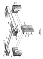
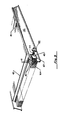
- a heat chamber 5 is depicted substantially enclosed by walls, shown in section, each formed from a series of elongated and folded U-shaped mats 6 in parallel.
- the mats 6 are prepared from ceramic fiber insulating material and are in snug side-by-side relationship, with each being reinforced and linked to guide channels, in a manner as will be hereinafter depicted for example in Fig. 2.
- the disposition of pressure plates 12 are more particularly shown.
- Each of the pressure plates 12 is compressed against a corner section face of a U-shaped mat 6 by adjustable force means, not shown, transmitted through threaded bolts 13.
- a roof or cover is positioned over the heat chamber 5. Over the heat chamber 5 depending U-shaped roof blankets 16 are disposed. Each of the U-shaped roof blankets 16 has a pair of depending blanket legs 16a. A reinforcing or support bar, not shown, is retained within the fold of each U-shaped roof blanket 16. To each reinforcing bar there are attached posts, also not shown, which pierce through each roof blanket 16 and terminate in a generally C-shaped grip head 10. The grip heads 10 then serve as sliding hangers, gripping in this fashion around a portion of a T-bar 4 in slidable engagement. At each end, the T-bar is held in place, as by welding, to end plates, not shown.
- a spring loaded compression plate 12 abuts against the roof blankets 16. Pressure is exerted by the spring 14coiled around posts 15 of the spring loaded compression plate 12.
- the end plates, not shown, are firmly affixed to the furnace chamber structure, by means not shown.
- the roof blanket leg sections rest 16a upon the upper surface plane of the wall mats 6, thereby providing a covered insulation structure for the heat chamber 5.
- their dimension along the T-bar 4 can be such that they limit the maximum degree of compression of the roof blankets 16.
- the roof structure by itself will be adaptable as a general heat insulation structure, e.g., in use as a soaking pit cover or the like.
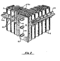
- Fig. 2 shows an arrangement for providing support for the insulation structure.
- a series of substantially W-shaped ceramic fiber insulation blankets 6 provide insulation by being disposed in parallel, side-by-side relationship.
- the blankets 6 are arranged in such a manner as to provide interengagement of blanket leg sections 6a between adjacent blankets 6.
- Reinforcing or support bars 7 are then retained in folds of the blankets 6.
- engaging posts 8 To each reinforcing bar 7 there are attached engaging posts 8, each of which pierce through the blanket and terminate in a generally C-shaped grip head 10.
- the grip heads 10 then grip around a portion of a T-bar 4 in slidable engagement.
- the T-bar 4 is held firmly in place by support members, not shown.
- a pressure plate 12 abuts against the first, or cornermost, W-shaped blanket 6, which thereby becomes the corner-forming element of the wall.
- the pressure plate 12 is compressed against the corner section of this W-shaped blanket 6 by force means, not shown.
- the adjoining and intersecting wall section is likewise placed under compressive force.
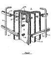
- FIG. 3 A perspective view in partial section of an outer corner portion of intersecting heat chamber walls of different structure has been depicted in Fig. 3.
- the heat chamber walls intersect at a right angle to form a corner for partially enclosing a heat chamber 5.
- Each intersecting wall section is composed of a series of elongated and folded U-shaped mats 6 arranged such that a major portion of the outer surfaces of a leg section 6a of one mat 6 abuts against a leg section 6a of an adjacent mat 6.
- Adjacent individual mats 6, in series collectively form at least a portion of a heat chamber wall and have their leg sections 6a projecting inwardly to the heat chamber 5.
- Each individual U-shaped mat 6 is folded around a support or reinforcing bar 7.
- a series of engaging posts 8 are affixed.
- the post leg 8a pierces through the fiber at the fold of the mat 6 from the reinforcing bar 7.
- the post leg 8a terminates in a post head 8b which is contained within a guide channel 9.
- the channel 9 forms a portion of the reticulate frame at the cold face of the heat chamber wall.
- the guide channels 9 are securely affixed, such as by welding, to support bars 11 which are rigidly held in place to other frame structure of the heat chamber by means not shown.
- a pressure plate 12 abuts against the first U-shaped mat 6 of the wall.
- the pressure plate 12 is compressed against the corner section face of this U-shaped mat 6 by adjustable force means, not shown, transmitted through the threaded sections 13. Compression against the mat 6 thereby compresses all of the adjacent mats 6 that are in side-by-side relationship in the direction of the exerted compressive force.
- the intersecting wall section is likewise placed under compressive force.
- the hot face of the wall is formed at least in part by the leg sections 6a of the mats 6. Where adjacent mats 6 form the corner by the end plate 12, some mat leg sections 6a from one wall abut up against a mat leg section 6a of the mats from the other wall. This engagement, shown in Fig. 3 at a right angle, forms the corner of the heat chamber 5.
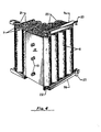
- Fig. 4 there is depicted an alternate form for engaging ceramic fiber insulation with guide channels 9a, 9b.
- the insulation is provided by two continuous blanket insulation elements 25 folded in corrugated manner to provide an interengaged, corrugation pattern.
- the support or reinforcing bars 7 engaged within folds of the continuous blanket insulation elements 25 extend upwardly beyond the upper face of the insulation elements 25 and terminate in a support bar head 21.
- the head 21 of each reinforcing bar 7 is then engaged in the upper guide channel 9a.
- the foot 22 of each reinforcing bar rests in the lower guide channel 9b.
- Each guide channel 9a and 9b contains flaps 23 which can be moved aside to facilitate the movement of the reinforcing bars 7 in and out of the guide channels 9a and 9b. These channels are then fixed to heat chamber structure by means not shown.
- a pressure plate 12 abuts against the cornermost leg of the insulation elements 25.
- the pressure plate 12 is compressed against the corner leg section face of the insulation element 25 by adjustable force means, not shown, transmitted through the threaded sections 13. Compression against the cornermost leg section thereby compresses all of the adjacent folded sections of the insulation elements 25 that are in side-by-side relationship in the direction of the exerted compressive force.
- the intersecting wall section is likewise placed under compressive force.
- a roof or cover particularly adapted for use as a soaking pit cover is shown in partial section.
- U-shaped roof blankets 16 are used as the principal covering element.
- Each of the U-shaped roof blankets 16 has a pair of depending blanket legs 16a.
- a support or reinforcing bar, not shown, is retained within the fold of each U-shaped roof blanket 16.
- posts also not shown, which pierce through each roof blanket 16 and terminate in a generally C-shaped grip head 41.
- the grip heads 41 then serve as sliding hangers, gripping in this fashion around a portion of a T-bar 42 in slidable engagement.
- the T-bar is held in place, as by welding, to end plates, not shown.
- a spring loaded compression plate 45 abuts against the roof blankets 16. Pressure is exerted by the springs 44 coiled around posts 47 of the spring loaded compression plate 45.
- the end plates 43 are firmly affixed to the furnace chamber structure, by means not shown. In construction, placement of the cover, as over a soaking pit, provides for the resting of the end plates 43 at the edge of the soaking pit, not shown, thereby providing a covered insulation structure of roof blankets 16.
- their dimension along the T-bar 42 can be such as to limit the maximum degree of compression of the roof blankets 16.
- the corner of the insulation structure may be arranged so as to transmit compressive force from such corner along each intersecting wall segment.
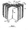
- substantially W-shaped ceramic fiber insulation blankets 61 are shown in interengaged manner with substantially U-shaped blankets 62.
- the U-shaped blankets 62 are inverted in position with respect to the W-shaped blankets 61 such that U-shaped blanket legs 62a extend into the spaces between the W-shaped blanket legs 61 a.
- a wall-type structure is thereby formed by a continuum of such blankets in series.
- an L-shaped bridging blanket 63 has one leg 63a interengaged in one wall and the remaining leg 63b interengaged with the other wall blanket insulation structure.
- a rolled blanket 64 is placed at the outermost corner section.
- the W-shaped blankets 61 and U-shaped blankets 62 are supported by means not shown, in a manner such as depicted in Figs. 2-4, and are linked in supportive manner to a frame, also not shown, and also in a manner such as depicted in Figs. 2-4.
- the L-shaped bridging blanket 63 is held firmly in place by interengagement of the blanket legs 63a and 63b with the wall blankets.
- a right angle pressure plate 65 abuts against the rolled blanket 64 at the corner in a manner such that one pressure plate leg 65a is in parallel relationship with the legs of the W-shaped blankets 61 and U-shaped blankets 62 of one wall whereas the remaining pressure plate leg 65b is positioned in parallel relationship with the legs 61a and 61 b of the W-shaped blankets 61 and U-shaped blankets 62 of the adjacent intersecting wall.
- the right angle pressure plate 65 is compressed against the corner, by force means not shown, transmitted through the threaded sections 66.
- the pressure plate 65 is insulated from the heat chamber by means of both the rolled blanket 64 and the L-shaped bridging blanket 63.
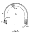
- a curvilinear insulation structure of the present invention is depicted. More particularly, the generally horseshoe-shaped insulation structure is used in part to confine a heat chamber 91.
- This heat chamber 91 is enclosed by means of ceramic fiber U-shaped blankets 92.
- the blankets 92 contain support or reinforcing bars (not shown) to which there are attached posts 97 which pierce through the blanket and terminate in a post head - 93.
- the post heads 93 interengage with a horseshoe-shaped guide channel 94.
- a compression plate 95 is then positioned at each end of the leg section of the horseshoe. Compressive force is transmitted through threaded connections 96 to each compression plate 95 by means not shown. It is also contemplated that such structure will be useful in upright position whereby the compression plates 95 exert compressive force upwardly and the horseshoe-shaped structure provides both sides and roof for a heat chamber 91 of generally tunnel shape.
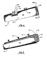
- a ceramic fiber insulation module shown generally at 101 is a U-shaped ceramic fiber insulation blanket 102 having depending, parallel blanket leg sections 102a and a bridging portion 102b.
- a support or reinforcing bar 103 is retained in the fold of the blanket 102 as a support element interengaged at the bridging portion 102b.
- the blanket 102 is generally shaped with broad longitudinal side surfaces 104 which can be snugly engaged, by externally applied pressure means, not shown, against like surfaces of similarly structured ceramic fiber insulation structure, also not shown.
- the fiber insulation module 101 can be linked for slidable movement with a support frame.
- a W-shaped ceramic fiber insulation blanket 121 has outer parallel leg sections 121a presenting broad fiber faces 125 for engagement with similarly structured surfaces, e.g., as found in U-shaped, S-shaped, or other W-shaped modules, not shown.
- the blanket 121 has inner parallel leg sections 121b containing a bridging portion 121c. Nestled in the fold between the inner leg sections 121b, at the bridging portion 121c, is a support bar or rod 122.
- the support rod 122 Directly attached to the support rod 122 are several posts 123 each of which protrudes directly from the support rod 122 at the blanket fold and terminates in a cap, or tab, 124 beyond the ceramic fiber blanket 121.
- the cap 124 is adapted for engagement with the channel or groove section of a bar element forming a part of a support frame, all not shown.
- the module can be linked for slidable movement within a support frame channel.
- Such modules as depicted in Figs. 8 and 9 can be particularly serviceable for use in the reconstruction or repair of a heat insulating wall type structure and especially of such structure as taught in the present invention.
- the pressure plate 12 can be spring loaded to provide for automatic shrinkage compensation along the wall.
- shrinkage compensation can be accomplished by any suitable means, e.g., springs, hydraulic, pneumatic or counterbalancing means.
- pressure is released from the pressure plate 12 thereby permitting sliding of the blankets against the pressure plate until the cornermost mat 6 is disengaged from the guide channels 9.
- Individual mats 6 can then be removed and replacement mats 6, or such replacement modules as shown, for example, in Fig. 9, can be inserted in their place.
- individual mats 6 are merely placed into the wall section by engaging the posts 8 into the guide channels 9 and slidably moving the individual mats 6 along the wall.
- a structure such as depicted in Fig. 4 can be employed.
- the ceramic fiber blankets 6 can not only be removed or inserted at the corner but also when the flaps 23 in the guide rails 9a and 9b are opened the reinforcing bars 7 for the blankets 6 may be removed or inserted.
- Such structure will be particularly useful where unitized mat sections, e.g., U-shaped or S-shaped or W-shaped units, are employed in the heat chamber wall. Such unitized structure would also be particularly useful in replacing wall sections removed from the corner.
- the C-shaped grip heads could be replaced by rings placed around an exterior support bar.
- a C-shaped guide bar could be interengaged by T-shaped heads located at the ends of the linkage means from the blankets.
- the L-shaped bridging blanket 63 of Fig. 6 could be useful in differing corner construction such as those depicted herein so long as sufficient blanket material is provided in the heat chamber to compensate for wall movement as pressure is exerted against the wall. It is also contemplated that two or more of the L-shaped bridging blankets 63 could be used in an individual corner section, typically in adjacent side-by-side relationship.
- the walls and cover of the heat chamber 5 enclosure are of ceramic fiber insulation and it is contemplated, for example in a slot forge furnace, that the floor of the furnace' would be of conventional furnace brick. Likewise the cover need not be as shown in Fig. 1, but can be provided by more conventional furnace construction.
- ports and inlets can be accommodated in conventional manner.
- ceramic fiber insulation blanket compression can be exerted for the insulation around wall ports and inlets thereby providing for enhanced heat retention in the heat chamber.
- adjacent blankets are in snug relationship, adjacent faces may be held together in compression alone.
- the insulation support means need not be sufficient to insure that insulation blankets will be freestanding. Blanket interengagement and linking of the support means to a frame member can assist in blanket support. Compression can furthermore facilitate such support.
- the support means thus need be only sufficient to prevent blankets from falling away from the frame, e.g., prevent the roof blankets 16 in Fig. 1 from falling into the heat chamber 5 located below the roof.
- the frame members preferably provide a foraminous or open framework, e.g., a lattice-type framework. Thus, girders, channels, beams, rods, reticulated metal covers and the.like are most often found as frame and cover members. Such preferred open frame structure can lead to ease of reconstruction and repair.
- the cold face of the blankets is thus preferably free from base plates, top plates and similar plate-type structure.
- elements of the overall structures discussed herein may generally be considered as metal elements, it will be appreciated that for certain structures lightweight ceramic materials may be suitable.
- the channels are typically rolled metal channels, the plates are metal plates, and so on.
Landscapes
- Engineering & Computer Science (AREA)
- Mechanical Engineering (AREA)
- General Engineering & Computer Science (AREA)
- Chemical & Material Sciences (AREA)
- Ceramic Engineering (AREA)
- Furnace Housings, Linings, Walls, And Ceilings (AREA)
Claims (13)
Priority Applications (1)
| Application Number | Priority Date | Filing Date | Title |
|---|---|---|---|
| AT85810164T ATE40463T1 (de) | 1984-04-19 | 1985-04-15 | Nichtfeste waermekammerisolierung. |
Applications Claiming Priority (4)
| Application Number | Priority Date | Filing Date | Title |
|---|---|---|---|
| US60219784A | 1984-04-19 | 1984-04-19 | |
| US602197 | 1984-04-19 | ||
| US06/711,387 US4791769A (en) | 1984-04-19 | 1985-03-13 | Movable heat chamber insulating structure |
| US711387 | 1985-03-13 |
Publications (2)
| Publication Number | Publication Date |
|---|---|
| EP0165205A1 EP0165205A1 (de) | 1985-12-18 |
| EP0165205B1 true EP0165205B1 (de) | 1989-01-25 |
Family
ID=27084069
Family Applications (1)
| Application Number | Title | Priority Date | Filing Date |
|---|---|---|---|
| EP85810164A Expired EP0165205B1 (de) | 1984-04-19 | 1985-04-15 | Nichtfeste Wärmekammerisolierung |
Country Status (9)
| Country | Link |
|---|---|
| US (1) | US4791769A (de) |
| EP (1) | EP0165205B1 (de) |
| JP (1) | JPS6122190A (de) |
| AU (1) | AU4134385A (de) |
| BR (1) | BR8501812A (de) |
| CA (1) | CA1266609A (de) |
| DE (1) | DE3567961D1 (de) |
| ES (1) | ES8609559A1 (de) |
| MX (1) | MX162282A (de) |
Families Citing this family (12)
| Publication number | Priority date | Publication date | Assignee | Title |
|---|---|---|---|---|
| GB2190167B (en) * | 1986-05-09 | 1990-05-09 | Thomas James Twort | Furnace pipe insulation |
| GB8618852D0 (en) * | 1986-08-01 | 1986-09-10 | Hi Temp Inc | Lining of heat chamber |
| DE3727937A1 (de) * | 1987-08-21 | 1989-03-02 | Didier Werke Ag | Waermeisolierung von gleit-, trag- oder querrohren einer industriellen feuerungsanlage |
| NL8900114A (nl) * | 1989-01-18 | 1990-08-16 | Milutin Gnjatovic | Werkwijze voor het isoleren van een oven en oven vervaardigd volgens de werkwijze. |
| US5176876A (en) * | 1990-10-10 | 1993-01-05 | Simko & Sons Industrial Refractories Inc. | Insulating ceramic fiber batting module, anchoring system, ladle cover assembly and method of assembly |
| US5234660A (en) * | 1990-10-10 | 1993-08-10 | Simko & Sons Industrial Refractories, Inc. | Insulating ceramic fiber batting module, anchoring system, ladle cover assembly and method of assembly |
| US5209038A (en) * | 1991-08-19 | 1993-05-11 | Robbins Michael K | Heat chamber lining |
| US5701711A (en) * | 1996-07-22 | 1997-12-30 | The Babcock & Wilcox Company | Hanger assembly for lagging panel |
| US7564007B2 (en) * | 2007-05-14 | 2009-07-21 | Bailey James G | Kiln removable ceramic element holder |
| CN104515143B (zh) * | 2013-09-30 | 2017-05-17 | 中山市兴和生物能源科技有限公司 | 一种生物质燃烧机燃烧炉结构 |
| CN105571323B (zh) * | 2016-01-27 | 2018-06-29 | 江苏南方节能科技有限公司 | 一种炉顶安装工艺 |
| CN120760474B (zh) * | 2025-09-03 | 2025-11-21 | 西安博莱炉业科技股份有限公司 | 一种耐火材料球形顶盖整体安装设备及工艺 |
Family Cites Families (27)
| Publication number | Priority date | Publication date | Assignee | Title |
|---|---|---|---|---|
| US2656717A (en) * | 1950-02-06 | 1953-10-27 | Fourmanoit Jean Charles | Device for avoiding the dislocation of furnaces or ovens |
| US2987856A (en) * | 1958-05-21 | 1961-06-13 | Levi S Longenecker | Interlocking chain wall |
| US3030737A (en) * | 1959-06-29 | 1962-04-24 | Chicago Fire Brick Co | Casing structure for furnace |
| US3832815A (en) * | 1973-01-29 | 1974-09-03 | Flinn & Dreffein Eng Co | Modular insulation of fibrous material |
| US3854262A (en) * | 1973-05-01 | 1974-12-17 | Babcock & Wilcox Co | Inpaled and compressed fibrous furnace lining |
| US3952470A (en) * | 1974-06-03 | 1976-04-27 | J T Thorpe Company | Furnace lining apparatus |
| US4001996A (en) * | 1974-06-03 | 1977-01-11 | J. T. Thorpe Company | Prefabricated insulating blocks for furnace lining |
| GB1562203A (en) * | 1975-08-11 | 1980-03-05 | Johns Manville | Prefabricated insulating blocks for lining walls and roofs |
| NL7603237A (nl) * | 1976-03-26 | 1977-09-28 | Plibrico B V | Samengesteld bekledingsblok. |
| US3990203A (en) * | 1976-03-29 | 1976-11-09 | Greaves James R | Insulated ceramic fiber panels for portable high temperature chambers |
| US4088825A (en) * | 1976-08-04 | 1978-05-09 | General Electric Company | Electric furnace wall construction |
| GB1562555A (en) * | 1977-03-08 | 1980-03-12 | British Steel Corp | Furnace closure member |
| NO148723C (no) * | 1977-04-14 | 1983-11-30 | Isomax Ing Handel | Fremgangsmaate for fremstilling av en ovnsforing bestaaende av ett eller flere fibersjikt |
| US4336086A (en) * | 1977-08-24 | 1982-06-22 | Rast James P | Method of lining a furnace with roll-type insulation |
| US4194282A (en) * | 1978-04-28 | 1980-03-25 | Johns-Manville Corporation | Method and apparatus for filling seams between adjacent fiber blanket insulation modules |
| DE2856441A1 (de) * | 1978-12-28 | 1980-07-17 | Uhde Gmbh | Vorrichtung zur innenwandauskleidung von industrieoefen |
| JPS5832136Y2 (ja) * | 1979-02-02 | 1983-07-16 | 日本碍子株式会社 | セラミツクフアイバ−を内張材とする窯炉 |
| NL185584C (nl) * | 1979-04-13 | 1990-05-16 | Heattreatment Advising Co | Oven met een wand van warmte-isolerend materiaal. |
| US4339902A (en) * | 1980-06-30 | 1982-07-20 | Manville Service Corporation | Multiple layer thermal insulation device |
| EP0053875B1 (de) * | 1980-12-05 | 1986-12-17 | Eltech Systems Corporation | Wärmeisolierende Auskleidungsplatte für hohe Temperaturen |
| US4411621A (en) * | 1980-12-05 | 1983-10-25 | Miller Thomas M | Furnace wall construction |
| US4429504A (en) * | 1981-03-20 | 1984-02-07 | Manville Service Corporation | Fiber blanket insulation module |
| US4425749A (en) * | 1981-12-14 | 1984-01-17 | Manville Service Corporation | Furnace lining module |
| GB2112119A (en) * | 1981-12-23 | 1983-07-13 | Fuel Conservation Services | Heat insulating panels |
| US4640202A (en) * | 1984-07-30 | 1987-02-03 | Eltech Systems Corporation | Readily repairable and lightweight cover for a heated vessel |
| US4605583A (en) * | 1984-07-30 | 1986-08-12 | Industrial Insulations, Inc. | Heat insulating module for a high temperature chamber |
| US4633637A (en) * | 1986-01-30 | 1987-01-06 | Industrial Insulations, Inc. | Heat insulating module and method of assembly for use in a high temperature chamber |
-
1985
- 1985-03-13 US US06/711,387 patent/US4791769A/en not_active Expired - Lifetime
- 1985-04-15 DE DE8585810164T patent/DE3567961D1/de not_active Expired
- 1985-04-15 EP EP85810164A patent/EP0165205B1/de not_active Expired
- 1985-04-16 CA CA000479222A patent/CA1266609A/en not_active Expired
- 1985-04-16 BR BR8501812A patent/BR8501812A/pt unknown
- 1985-04-17 MX MX204998A patent/MX162282A/es unknown
- 1985-04-17 AU AU41343/85A patent/AU4134385A/en not_active Abandoned
- 1985-04-18 ES ES542400A patent/ES8609559A1/es not_active Expired
- 1985-04-19 JP JP60084359A patent/JPS6122190A/ja active Pending
Also Published As
| Publication number | Publication date |
|---|---|
| CA1266609A (en) | 1990-03-13 |
| US4791769A (en) | 1988-12-20 |
| BR8501812A (pt) | 1985-12-17 |
| AU4134385A (en) | 1985-10-24 |
| EP0165205A1 (de) | 1985-12-18 |
| MX162282A (es) | 1991-04-19 |
| ES8609559A1 (es) | 1986-09-01 |
| DE3567961D1 (en) | 1989-03-02 |
| JPS6122190A (ja) | 1986-01-30 |
| ES542400A0 (es) | 1986-09-01 |
Similar Documents
| Publication | Publication Date | Title |
|---|---|---|
| EP0165205B1 (de) | Nichtfeste Wärmekammerisolierung | |
| US4411621A (en) | Furnace wall construction | |
| US4524702A (en) | Readily repairable and lightweight cover for a heated vessel | |
| US4440099A (en) | Ceramic fiber modular assemblies for lining furnace walls | |
| JPH0121436B2 (de) | ||
| US4653171A (en) | Refractory insulation mounting system and insulated structures | |
| NL8200074A (nl) | Isolatiemodulen voor electrische ovens. | |
| GB2046417A (en) | Industrial furnace with ceramic insulating modules having internal grid support | |
| US4829734A (en) | Ceramic fiber insulation module and method of assembly | |
| CA1222613A (en) | Readily repairable and lightweight insulating cover for a heated metal container | |
| US4442650A (en) | Girder construction | |
| US4606473A (en) | Readily repairable and lightweight insulating cover for a heated metal container | |
| US5188528A (en) | Method and apparatus for lining the interior surface of a high temperature chamber with heat insulation material | |
| JPS6399491A (ja) | 熱チヤンバ−のライニング | |
| US4512738A (en) | High-temperature kilns | |
| JP3133954B2 (ja) | バーナタイル | |
| US4344753A (en) | Method for reducing the thermal inertia of a furnace or oven wall and insulated wall produced thereby | |
| US5176876A (en) | Insulating ceramic fiber batting module, anchoring system, ladle cover assembly and method of assembly | |
| JPS58501593A (ja) | ロツド留めされたアコ−デオン折ライニングモジユ−ル | |
| RU2118775C1 (ru) | Способ и система для облицовки пространств с высокой температурой | |
| CN85105068A (zh) | 移动式加热室绝热层结构 | |
| US5234660A (en) | Insulating ceramic fiber batting module, anchoring system, ladle cover assembly and method of assembly | |
| US5332116A (en) | Ceramic fiber insulation structure with readily repairable perimeter insulation | |
| EP0053875B1 (de) | Wärmeisolierende Auskleidungsplatte für hohe Temperaturen | |
| RU2094723C1 (ru) | Блок футеровки свода печи |
Legal Events
| Date | Code | Title | Description |
|---|---|---|---|
| PUAI | Public reference made under article 153(3) epc to a published international application that has entered the european phase |
Free format text: ORIGINAL CODE: 0009012 |
|
| AK | Designated contracting states |
Designated state(s): AT BE CH DE FR GB IT LI LU NL SE |
|
| 17P | Request for examination filed |
Effective date: 19860517 |
|
| 17Q | First examination report despatched |
Effective date: 19870320 |
|
| GRAA | (expected) grant |
Free format text: ORIGINAL CODE: 0009210 |
|
| AK | Designated contracting states |
Kind code of ref document: B1 Designated state(s): AT BE CH DE FR GB IT LI LU NL SE |
|
| PG25 | Lapsed in a contracting state [announced via postgrant information from national office to epo] |
Ref country code: IT Free format text: LAPSE BECAUSE OF FAILURE TO SUBMIT A TRANSLATION OF THE DESCRIPTION OR TO PAY THE FEE WITHIN THE PRESCRIBED TIME-LIMIT;WARNING: LAPSES OF ITALIAN PATENTS WITH EFFECTIVE DATE BEFORE 2007 MAY HAVE OCCURRED AT ANY TIME BEFORE 2007. THE CORRECT EFFECTIVE DATE MAY BE DIFFERENT FROM THE ONE RECORDED. Effective date: 19890125 Ref country code: SE Effective date: 19890125 Ref country code: AT Effective date: 19890125 Ref country code: CH Effective date: 19890125 Ref country code: LI Effective date: 19890125 Ref country code: NL Effective date: 19890125 |
|
| REF | Corresponds to: |
Ref document number: 40463 Country of ref document: AT Date of ref document: 19890215 Kind code of ref document: T |
|
| REF | Corresponds to: |
Ref document number: 3567961 Country of ref document: DE Date of ref document: 19890302 |
|
| PG25 | Lapsed in a contracting state [announced via postgrant information from national office to epo] |
Ref country code: LU Free format text: LAPSE BECAUSE OF NON-PAYMENT OF DUE FEES Effective date: 19890430 |
|
| REG | Reference to a national code |
Ref country code: CH Ref legal event code: PL |
|
| ET | Fr: translation filed | ||
| NLV1 | Nl: lapsed or annulled due to failure to fulfill the requirements of art. 29p and 29m of the patents act | ||
| PLBE | No opposition filed within time limit |
Free format text: ORIGINAL CODE: 0009261 |
|
| STAA | Information on the status of an ep patent application or granted ep patent |
Free format text: STATUS: NO OPPOSITION FILED WITHIN TIME LIMIT |
|
| 26N | No opposition filed | ||
| PGFP | Annual fee paid to national office [announced via postgrant information from national office to epo] |
Ref country code: GB Payment date: 19940412 Year of fee payment: 10 Ref country code: FR Payment date: 19940412 Year of fee payment: 10 |
|
| PGFP | Annual fee paid to national office [announced via postgrant information from national office to epo] |
Ref country code: DE Payment date: 19940427 Year of fee payment: 10 Ref country code: BE Payment date: 19940427 Year of fee payment: 10 |
|
| REG | Reference to a national code |
Ref country code: FR Ref legal event code: TP |
|
| REG | Reference to a national code |
Ref country code: GB Ref legal event code: 732E |
|
| PG25 | Lapsed in a contracting state [announced via postgrant information from national office to epo] |
Ref country code: GB Effective date: 19950415 |
|
| PG25 | Lapsed in a contracting state [announced via postgrant information from national office to epo] |
Ref country code: BE Effective date: 19950430 |
|
| BERE | Be: lapsed |
Owner name: ENGINEERED THERNAL SYSTEMS INC. Effective date: 19950430 |
|
| GBPC | Gb: european patent ceased through non-payment of renewal fee |
Effective date: 19950415 |
|
| PG25 | Lapsed in a contracting state [announced via postgrant information from national office to epo] |
Ref country code: FR Effective date: 19951229 |
|
| PG25 | Lapsed in a contracting state [announced via postgrant information from national office to epo] |
Ref country code: DE Effective date: 19960103 |
|
| REG | Reference to a national code |
Ref country code: FR Ref legal event code: ST |